The 4 LED temperature indicator circuit discussed here is very useful for getting a visual information regarding the state of temperature which is to be monitored.
Circuit Operation
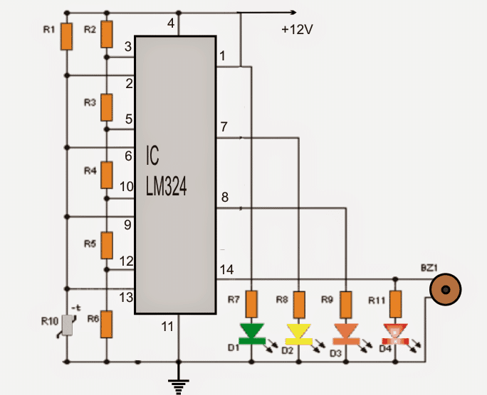
In the circuit temperature status is displayed using four LEDs.
- A green LED, indicating that the temperature is in the desirable level
- Two yellow LEDs are included to indicate that the temperature is higher than normal, and the situation is unsafe.
- A red LED warning status tells that the temperature is very high and must be acted upon quickly.
To complement the high temperature red LED warning a buzzer is included in the circuit which emits an audible warning note to alert regarding the emergency.
The circuit is executed using four comparators inside the IC LM324. This is an outstanding chip which has four operational amplifiers on par with 741 type together in one package.
The first stage of the diagram shows a voltage divider network formed with the help of R2, R3, R4, R5 and R6 resistors.
Here the voltages are fixed referenced at 2.4V, 4.8V, 7.2V, 9.6V.
Each of these voltages is connected directly to the non-inverting pinout (+) of the operational amplifiers which is being used as comparators
The upper lead of the thermistor (R10) connects directly with all inverting (-) terminals of the opamps.
If the subjected temperature varies, the voltage also proportionately varies at the upper pin of the thermistor.
This induced responsive voltage is compared with the opamp comparators across their non-inverting terminals and in response to lesser voltages sends correspondingly high voltage comparator output activating the relevant LED.
As the temperature rises, conditions across the thermistor begins getting lower illuminating the LEDs in sequence.
When the lower most comparator is activated, the red LED lights and activates the "buzzer" giving an audible alert tune that may be considered crucial if the device needs to be safeguarded.
Circuit Diagram
How to Select the Resistors
If you wish to change the LED switching range across a desired input detection range, you may adjust the reference resistor values as per your requirement, as I have explained below:
As we can understand that the 4 op amps of the LM324 are set up as comparators, wherein the non-inverting pins 3, 5, 10, 12 are clamped to the corresponding fixed reference levels determined by the resistors R2----R6.
The inverting inputs of the 4 op amps are joined in common and connected with another resistive divider formed by R1/Thermistor. The potential across this resistive divider junction varies depending on the variation in the temperature.
This varying temperature dependent potential across the inverting inputs of the op amps is compared with the relevant reference voltage levels across the non-inverting pins 3,5,10,12.
When the thermistor potential divider on the inverting pins go higher than the corresponding non-inverting pin reference levels, the output of the specific op amp becomes high, illuminating its connected LED.
This implies that by appropriately changing the reference resistor values of R2----R6 we can change the gaps between the LED illumination and thus the change the input detection range suitably across the 4 LEDs, as per a desired specification.
This may be done by using the formula:
Vout = Vin x R1 / (R1 + R2)
Where Vin is supply voltage which must be constant.
Vout becomes the desired reference level on a the given non-inverting pin.
R1 is the total value of the resistor(s) on the positive side of the relevant non-inverting pin
R2 is the total value of the resistor(s) on the ground side of the relevant non-inverting pin.
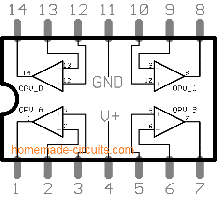
IC LM324 Pin Diagram
BOM for the proposed 4 LED temperature detector circuit
Resistors (1/4 watt 5% CFR)
- R2, R3, R4, R5, R6 = 5K
- R1 = 10K,
- R7, R8, R9, R11 = 220 Ohms
- LEDs: 1 green, 1 yellow, 1 red
- Buzzer = 1no
- IC LM324 - 1no
- R10 = 10K Thermistor (as shown below)
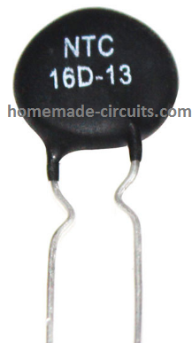
Note: for the thermistor, you must keep the terminals long enough, so that it can be terminated across the place where the temperature is in question.
Submitted by: Shweta sawant
UPDATE from the Admin
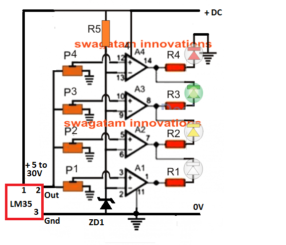
The accuracy and reliability of the above 4 LED temperature indicator circuit can be further improved by adding discrete presets to the 4 op amps and by replacing the thermistor with LM35 IC. The complete circuit is shown below:
Parts List
- All presets are 22K (linear)
- All resistors are 1K 1/4 watt
- ZD1 is 6V 1/4 watt zener diode
- LEDs are red, green, yellow, white 5mm 20mA
- Op amps are from the IC LM324
- Temperature sensor is LM35 IC



Questions & Answers
Hi, for this circuit, what is the maxmum and minimum °C range?
Thanks
Joseph
Hi, it will be between 25 and 125°C
Hello Sir Swagatam,
Thank you for the helpful schematic. I have tried to simulate this work in multisim using the singular op amps instead of the whole IC, but I am not getting the desired results. Is there something I am missing?
https://www.multisim.com/content/XYigZxAfkhDZWnRDr2ZCKD/testing-found-circuit/open/
Thank you,
Roman
Thank you Roman,
Simulators softwares are not always correct. However, I can assure you that practically the circuit will work as intended. So you can try it practically and check the results, it will work for sure.
Hi is it possible for me to see the calculation step for the above circuit
Hi, I have added the required data in the article.
Dear sir, the first circuit can i use for incubator after modify with relay and selected switch for selecting desire temperature ?
Yes you can do it!
Hello,
My lab partner and I are using this circuit for a final project, and are wondering how the multimeter plays into the entire circuit? In addition, would it be possible for you to go through the circuit, step by step? Finally, what do we have to do to actually know what temperature values each of the LEDs represent?
Thank you!
Hi, I have added another diagram in the article which uses individual presets for each op amp. Each of these presets can now be set sequentially for indicating the desired temperature levels across the 4 LEDs sequentially.
Hello!
Would you be able to send a picture of the completed circuit? My friend and I are attempting to recreate it, but are having some trouble understanding the op-amp and what to connect.
Hi, it was built long ago, so I do not have pics with me right now. However, I have updated the post with more details. I hope this will help you to understand the wiring and the parts better. Let me know if you have any more doubts.
Sir,
Please i need a solar heater circuit which i can warm my chicken coop in Winter season. And i want the circuit Design to come with Thermostat in oder to swich off when temperature reach 37fh and swich on at 35fh.Thanks
Kabiru,
for the thermostat you can try this circuit:
https://www.homemade-circuits.com/2012/04/how-to-make-automatic-refreigerator.html
for the solar heater you can buy any suitable solar panel matching your heater specs. You just have to connect it with the solar panel for the heating operations.
Hello sir Swagatam,
Can I wire this circuit like the one you posted in the link below?
https://www.homemade-circuits.com/3-step-dc-voltage-level-monitor/
I want connect it in such a way that I can vary the individual temperature levels for each LED to light up or go off. The LEDs will work in bar mode. I can reconfigure it to work in bar mode.
For the circuit in the link, can I replace the zener diode with the NTC and replace R2-R6 with 10k pots (using four pots this time)?
If I cannot, kindly suggest a way to wire the circuit so that it can work like the one in the link.
I would really love to upgrade this schematic by using LM35 which is a more accurate temperature sensor. Is it possible to wire LM35 and LM324 together? If it’s possible, kindly suggest how to.
Anticipating your usual prompt response.
Thank you.
Hi Godson, yes that’s definitely possible, you can try it.
Hello sir Swagatam,
Thank you very much for this schematic. As Kumar asked above, I also want to use the schematic to control a 220V AC fan. You suggested that a PWM circuit should be included. Can you please suggest such PWM circuit and how it can be used with the above schematic?
Thanks.
Hello Godson, Actually I misunderstood his question, and seem to have missed the 3 step switch in the question.
however for PWM you can try the following concept
https://www.homemade-circuits.com/pwm-air-blower-controller-circuit-for/
in the extreme left you can see a 10k preset, you can connect an NTC in series with its lower arm for the heat detection and fan control.
and make sure that the BC547 is made using two BJTs in a Darlington form.
hi what value is R1 can see the value anywere
R1 can be a 10k preset
HERE THERE NO IS POTENTIOMETER SO HOW CAN WE FIX THE REFERENCE VOLTAGE ??
R1 can be replaced with a pot for altering the reference value.
Dear Sir. i want to connect a 3 speed fan to above circuit posted by you.instead of LED, it will control the speed of fan.LED 1 fan off, LED 2 fan speed low LED 3 fan speed medium and LED 4 fan speed high. the fan motor will be driven by 240V and the circuit will b driven by 12V..this is easy to do by my problem is how to connect this speed controlling thing..i got a 3 speed control motor.how can this circuit control the switch of the fan
Dear Kissan, it's possible but you'll need to include a PWM circuit also along with the above detector circuit….only then the mentioned application will work.
4.bp.blogspot.com/-dV_lqrOPthA/VPaBXrZtXmI/AAAAAAAAJnQ/-xmDZcKgRLQ/s1600/temperarture%2Bindicator.png
Dear Sir. i want to connect a 3 speed fan to this circuit.instead of LED, it will control the speed of fan.LED 1 fan off, LED 2 fan speed low LED 3 fan speed medium and LED 4 fan speed high. the fan motor will be driven by 240V and the circuit will b driven by 12V..this is easy to do by my problem is how to connect this speed controlling thing..i got a 3 speed control motor.how can this circuit control the switch of the fan
Dear Swagatam,
Can a NTC resistor be used instead of the thermistor?
Regards,
Henrik
Thank you.
Dear Henrik,
I think both are one and the same, thermistor itself is a temperature dependent resistor, yes here it's a NTC thermistor