In this post I have explained a simple 3 phase solar submersible pump inverter circuit which can be made by configuring a few ICs and a few power devices. The idea was requested by Mr. Lufono and Mr. Sami.
Circuit Objectives and Requirements
- First of all i must say thanks to you and Mr. Lufono, I have many solar projects of solar tube well and want to make a three phase inverter and I connected 14 to 23 solar panels of 250 watts every solar panel 31 volts 8amp in series than I have 450 vdc to 750 vdc.
- My submersible pumps 5.5kw to 7.5 kw 3phase 220v and 380v 3phase.
- I also request that in the circuit auto motor speed control also needed, means when solar panel voltages up or down with the time and sunlight motor speed also adjust automatically.
- If igbt needed GP50R12KT3 or other no problem plz help me so so thanks .
The Design
I have already explained a simple single chip 3 phase full bridge inverter circuit, the same IC can be used for the proposed solar pump inverter circuit. The standard configuration of the 3 phase driver IC IRS2330 can be seen below:
Circuit Diagram
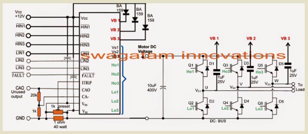
However since the mentioned 3 phase driver requires a dedicated 3 phase signal across its triggering inputs marked as HIN....LIN, it would be first important to learn about a simple 3 phase signal generator circuit using opamps which could be integrated with the above design for the intended outcome..
It doesn't need to be a sine wave 3 phase signals a simple square wave 120 degree phase shift PWM generator could be used for the application, as illustrated below:
3-Phase Generator Schematic
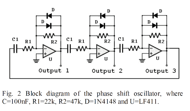
The above 3 phase generator circuit can be further modified in the following manner so that it can be fed to the 3 phase driver IC shown in the first image:
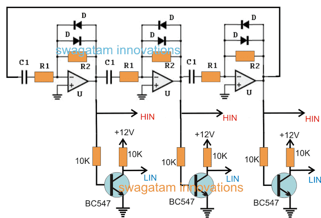
Using BJT Buffer Stage
Here we see how the outputs from the 3 phase generator opamps are buffered using transistor inverters for producing the required 3 out-of-phase channels for the HIN...LIN inputs of the IRS2330 3 phase inverter driver IC.
The load connected with the driver mosfets or IGBTs now would receive a square wave 3 phase operating voltage, which could be a submersible pump motor in our application as per the request.
In case the IC IRS2330 looks difficult to acquire in the local market, the following cheaper half wave solar submersible inverter circuit concept could be implemented, although with 50% less wattage efficiency.
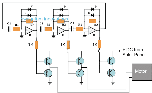
The BJTs could be replaced with appropriately rated mosfets or IGBTs...rest of the configuration is pretty straightforward and does not need much explanation.


Questions & Answers
salut mon frère !
ce très intéressant .
Thanks Godefroid, Glad you liked the post, let me know if you any questions…
hi,
you are not chapping output with PWM, not switching output transistors completely On and OFF. They work as leaner resistors. How hot they get? What efficiency of that inverter?
sir how to run 3 phase motor. 1 phase supply & direct dc power supply using vfd (a.c.draive) please sugest me 9624780985 jambukiya6@gmail.com
You can do it as explained in the above article, or as given in the following articles:
https://www.homemade-circuits.com/?s=3+phase+inverter
Greetings to you sir,
I will need this circuit setup ,that can control up to 15kw pump.
Hi Kenkenny, you can first try the above design with a smaller pump or load. If you succeed building it correctly then you can upgrade the IGBTs for a 15 kW load.
Hello sir
can use slimdip-l or scm1241 to replace irs2330?
The output voltage can be adjusted as desired
thanks,
Hello Ly,
Sorry I have not yet studied the ICs which you have mentioned, so I can’t suggest much about them.
Please can you illustrate how a DC solar freezer work? With it inverter circuit example.
I have not yet studied the solar freezer concept, so I am not sure about its working….
Thanks for your respond.
Como vai? Pode dar nomes a cada mosfet, para que eu possa fazer este circuito? obrigado.
Mosfets will depend on the load voltage and current. Select them according to their VDD and ID values, which must be 25% higher than the load specs.
Vou usar um alternador modificado para motor em 24 ou 36 volts, para mover uma bicicreta cargueira. Aproximado 800 wats..
You can try IRF3205 mosfets
Como vai? Nesta ultima imagem, posso usar BC547 e BC 557? Obrigado.
Hello, in the last image BC547/BC557 cannot be used, because they cannot handle high voltage, high current motor load.
you can use IGBT instead
That’s great, but what would be the output voltage to drive the pump. Is it possible to have an output of between 12 volts and 24 volts ac.
Thank you! yes, if the supply to the transistors is 12V or 24V then the output will be also a 3 phase 12V or 24V
Hi, I’m trying to do something similar with this circuit and I want to ask a question:
You noted that you connected 14 to 23 solar panels of 250 watts every solar panel 31 volts 8amp in series than I have 450 vdc to 750 vdc.
How did you reduce the dc voltage to 12V to supply the 3 phase driver IC IRS2330 ?
Thanks.
Hi, you can easily reduce 40V to 12V using a switching regulator, or using a 4k7 5 watt resistor, and a 12V zener diode
Hie Swag . Is there any circuit available for a single phase solar submersible pump which takes in a maximum of 300vdc from solar panels and inverted directly to 220VAc . I should also have a path for 220Ac input and output as 220v as well.
Could you assist with such design
Hi Binus, yes it is possible. You just have to build and optimize a full bridge inverter circuit for the purpose. You can refer to the following articles for more info:
https://www.homemade-circuits.com/simplest-full-bridge-inverter-circuit/
https://www.homemade-circuits.com/5kva-transformerless-inverter-circuit/
Hie Swag
Im Binus .i have a question regarding this solar pump inverter . Is that design applicable to single phase small pumps rating from 0.47kw to 1.1kw. And how much vdc maxim is required as in configurations of pvs ie series connection.
I would be grateful if you help me with a simple solar pump drive circuit for single phase and 3 phase . With a display and a minimised sensitive systems and that can adjust automatically the changes of the sunlight.
Best Regards
Binus
Hi Binus, the idea is simple, first you must have a solar panel ratted at 1.1 kw, then you must have an 1.1 kw inverter which can use the solar voltage and current to supply 220 V at 1.1 kw…once you have these two parameters fixed, you can easily run your pump motor from the installation.
For automatic adjustment to solar light you will require a solar tracker, that’s another parameter which will need to be achieved…
And also the inverter for it to use direct solar voltage and current to supply 220v what is needed to achieve that. Is the same way as the battery inverter circuit
To achieve that your solar panels must be rated at over 310 V DC
Okay series connection right and using which circuit. Do you have a circuit for that solar drive that can power a 1-2 horse power pump. And how best can i adjust a circuit incase the provided one is like 2.5kva and im in need of a 5kva .
Hi Swag. Is it possible to connect a single phase pump on a 3 phase solar drive and how. Also how can i adjust the circuit to single phase direct solar inverter.
Hi Binus, I don’t think a single phase pump can be connected to a 3 phase source, there’s no easy way to divert all the 3 phase into the single phase motor….
Hi Swag. Please I have four of 12 volt 200 amps / 10 hours batteries connected in parallel, I want to know if my 12 volt13 amp charger can charge it well. Thank you
Hi Afred,
To charge 4nos of 12 V 200 Ah batteries in parallel, you will need a charger rated at 14 V 80 amps…..your 3 amp charger will not work
You can add the smaller solar panel in series to get a final output of 310 V Dc and then use it with the second inverter circuit from this article:
https://www.homemade-circuits.com/5kva-transformerless-inverter-circuit/
All these can be very complex for anybody whose is new to electronics
Thank you Swag, now the issue is is the solar tracker responsible for automatic adjustment of pump speed due to the changes in sunlight. And the inverter should be able to display its input voltages and wattage as well as output.
If there’s any link to a guide for that i would appreciate.
Thank you Engineer Swag.
Hi Binus, for the inverter you can use the following design:
https://www.homemade-circuits.com/wp-content/uploads/2019/04/feedback-1024×460.png This design includes an automatic output voltage control.
For the solar tracker you can refer to the following circuit and mechanism set up:
Simple Solar Tracker System – Mechanism and Working
Thank you Swag for the inverter circuit. Does it have inbuilt battery charger controller or mppt. And what rating is the circuit
You are welcome Binus, no the circuit is only an inverter, it does not have a battery charger or MPPT….MPPT won’t be required if solar tracker is used. The rating can be increased by increasing the MOSFET power and the transformer power…
COMO VAI? NESTE PRIMEIRO ESQUEMA, QUAL MOSFET POSSO USAR, PARA UM MOTOR DE 1000 W ? OBRIGADO .
In the first diagram, IGBTs are shown but you can use MOSFETs also, the rating will depend on your specific application specification
OKAY? I THINK I CAN ASSEMBLE THIS SCHEME, FOR A MODIFIED ALTERNATOR ENGINE. BUT I PREFER MOSFET FOR BEING CHEAPER. I WOULD LIKE YOU TO HELP ME CHOOSE MOSFETS, FOR 1000 W. PLEASE THANK YOU.
Please provide voltage and current specifications also for the alternator….
HI, HOW ARE YOU? I BELIEVE IT IS BETTER, CONSIDER THE ALTERNATOR, MODIFIED, WITH 800 WATTS, VOLTAGE 24VOLTS, CURRENT 35 AP. IT WILL BE MOUNTED ON A LOAD BIKE, THANK YOU.
Hi, you can try any 100V 50 Amp MOSFETs, such as this:
https://www.mouser.in/datasheet/2/427/sqd50n10-8m9l-1764727.pdf
Dear sir,
we need a pcb for solar pump controller ,
you have solutions.
Thanks & regards
9786077355
Sorry Thilagar, I don’t make PCBs
sir vb1 vb2 vb3 kanha connect karana hai igbt se jo output nikal raha hai thank you sir
on the respective cathodes of BA159
Hi Swag
Back to the 3 phase generator system for a deep well pump. I am starting to get some gear together and am now doing a little more research.
Looking at the link you supplied (https://www.homemade-circuits.com/arduino-3-phase-inverter-circuit-with-code/) I am guessing that the output are square waves. Generally not a problem with most devices. However, I have read that induction motors may not respond well to square wave inputs. The deep well pumps around here are all induction as far as I know.
Am I wasting my time by continuing? I am hoping not with your advice. If it looks to be a problem then I need to expand my reach outside the box.
Thanks
Vic Braun
Hi Vic, I think you should try the above square wave design and see how it responds. Actually succeeding with the above design can be crucial, later on this design can be converted into a sinewave quite easily through an external circuit, if it becomes necessary.
Hi Mr Swagatam
Looked for your first name but didn’t find it. So we will have to be formal for the time being.
Great site.
I was a professional electrical engineer back in the dark ages before becoming a school teacher and lost touch with electronic design etc etc. So my knowledge is dated at best.
My question is:
In Australia, our voltages are 240V single and 415V 3 phase. What modifications would I need to make to your circuit to run a 5kW deep well pump. I am reasonably competent with building circuits etc.
I am wanting to start to become independent of the grid and this seems to be a good solution. I have plenty of solar panels.
Thanks
Vic Braun
Hi Victor, Swagatam is my fist name, you can call me “Swag”. I am Glad you liked my site! I would recommend you to build the following linked design. Due to presence of Arduino, the 3 phase generator section becomes a lot easier and accurate. You can build a smaller version first using lower rated mosfets, if everything goes well, you can replace the devices with higher rated mosfets or IGBTs as per the 5kva specs.
https://www.homemade-circuits.com/arduino-3-phase-inverter-circuit-with-code/
Let me know if you have further doubts!
Sir, please send me a circuit diagram about closed loop stepper motor driver . Nema 17 stepper motor i am using for my 3d printer. I want to add optical encoder to motor.so, please try to give me a circuit on hybrid stepper driver
Sorry Sudip, I do not have this circuit at this moment!!
Hi Swagatam,
I am staying in South Africa with nice sunshine conditions
I want to run my single phase swimming pool pump 0.75 kW directly from a solar panel – in the morning as soon as the solar panel preduce the correct voltage and amps the pump motor must start and in the evening when the sunshine fade the pump must stop. Have you got a circuit alraedy for this? Or can you tweak a circuit and design that will work?
Hi Giel,
I think you can simply try the last circuit based on IC 555 from the following article.
https://www.homemade-circuits.com/how-to-make-light-activated-day-night/
Connect the relay contacts with the motor, as soon as the sunlight is sufficient enough as per the selection of R1, the relay switches ON and operate the pump, and switches OFF as soon as the sunlight drops below the given threshold.
Thank you very much
Sir please provide circuits With pin diagram of three phase signal generator
you can try the following one instead, which is a tested design.
https://www.homemade-circuits.com/3-phase-signal-generator-using/
please note that the 3 phase inverter circuit is a hugely complicated circuit and absolutely not recommended for newcomers, build it at your own risk if you are not an expert in this field…
Can I use LM 324 in replace of LF411
yes you can try LM324…somebody told me that the opamp circuit does not work, but I don’t believe it because the circuit was referred from one of the top technical websites and looks correct to me..
Thanku so much sir
I will go to try this
Thanks for reply sir
Can I use single phase transformers in replace of three phase transformers
how will you connect a single phase transformer in this design??
Out put of mosfet connected to the input of transformers as single phase transformers
How increase voltage from 12v to 240v
B
please show me with a schematic how the single phase transformer would connected with the above circuit and also how the trafo’s output could be connected with a 3 phase load.
Sir I want to make three phase inverter
12v DC to 240v AC supply please sir guide me
Abhishek, I already have this circuit in this website, you can search it using the search box on top….
If we replace bjts by mosfets don't we need MOSFET driver?
yes that's right, you can try inverting the configuration, use P channel for the upper mosfets and N channel for the lower… and add 3V zener diodes to their gates for allowing a dead time.
I rebuild the circuit on every-circuit but cant seem to get it working where does the negative for solar panel feed on the have wave circuit
interpreting a simulators output can be difficult for me.
all the connections which are marked with "ground" symbols must be joined with the negative of the supply.
additionally the opamp supply pins will also need to be connected with a 12V voltage supply.
I hope you have connected all these appropriately.
Good day
I have a 24v solar pump that uses a 24v controller to run the brush less motor of the pump i would like to know how to build that controller the pump has 3 wires running it
You can use the concept which has been explained in the above article….
Hello Swagatam,is there any replacement for LF411 on the alternative circuit
Hello Lufono, you can use any other opamp having features like high slew rate, low power consumption and high speed performance….although these are not crucial for the suggested design but will help to achieve better overall response….you can try IC741 also and see if works or not….I believe it would also work.
make sure to use a 3V zener diode with the base resistor of the respective transistors to prevent small offset voltage causing false triggering of the BJT
Thanks sir i have no wards to say thanks and i say u my best teacher at e help.so so so thanks .May u live long with peace.
Thanks positive thinker, the pleasure is all mine!!
Hello Swagatam, it is going to take a while to receive the IRS2330 I have ordered from Aliexpress . in the meantime I want to use your suggested cheaper half wave solar submersible inverter circuit concept , since LF411 available Locally.My question is how do i connect LF11 to the circuit , and is it one LF11 or three, and for a 0.55KW Load , what will be the suitable IGBT or Mosfet. Will appreciate your assistance
Hello Lufono, you will need four LF411 ICs, and connect each one as shown in the article.
the mosfets could be IRf450 since the voltage is at the mains level.
Thanks for the quick respond , I am testing the above circuit on a breadboard , once all is well i will fabricate it on a pcb and post details , thanks again for a straight forward circuit for my solution
you are welcome lufono, please make sure you build and it stage-wise
sir I want contact with you by phone can you call me sir my number 919740790078 or give me your number sir please
sorry, a telephonic conversation may not be possible.
hello Sir I want 240vdc to 240vac single phase 2kw invertor and it's circuit diagram please suggest me sir
hello ragahvendra, you can either the above concept or the following one
https://www.homemade-circuits.com/2016/04/solar-inverter-circuit-for-15-ton-ac.html