In this post I have explained the main differences between an IGBT and a MOSFeT device. I have explained more about the facts from the following article.
Comparing IGTB with power MOSFETs
The insulated-gate bipolar transistor features a voltage drop which is significantly low when compared to a conventional MOSFET in the devices which have a voltage of higher blocking.
The n-drift region’s depth must also increase along with an increase in the rating of the blocking voltage of the IGBT and MOSFET devices; and the dropping needs to be decreased which results in a relationship which is a square relationship decrease in the forward conduction versus the device’s blocking voltage capability.
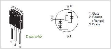
MosfetIGBT
The resistance of the n-drift region is reduced significantly decreased by introducing holes or minority carriers from the p-region which is the collector to the n-drift region during the process of the forward conduction.
But this reduction in the resistance of the n-drift region on the on-state forward voltage comes with the following properties:
How IGBT Works
The reverse flow of the current is blocked by the additional PN junction. Thus, it can be deducted that IGBTs are not able to conduct in the reverse direction like the other device such as MOSFET.
Thus, an additional diode which is known as freewheeling diode is placed in the bridge circuits where there is a need for the flow of reverse current.
These diodes are placed in parallel to the IGBT device in order to conduct the current in reverse direction. The penalty in this process was not as severe as it was assumed in the first place, because the discrete diodes give very high performance than the MOSFET’s body diode since IGBT usage is dominated at the higher voltages.
The rating of reverse bias of the n-drift region to the collector p-region diode is mostly of tens of volts. Thus, in this case, an additional diode needs to be used if the reverse voltage is applied by the circuit application to the IGBT.
A lot of time is taken by the minority carriers in order to enter, exit, or recombine which are injected into the n-drift region at every turn on and turn off. Thus, this results in switching time to be longer and hence significant loss in the switching in comparison to power MOSFET.
The on-stage drop of voltage in forward direction in the IGBT devices showcases a very different behavioral pattern when compared to the power devices of MOSFETS.
How Mosfets Work
The voltage drop of the MOSFET can be easily modeled in the form of a resistance, with the voltage drop being in proportion to the current. In contrast to this, the IGBT devices consist of a voltage drop in the form of a diode (mostly in the range of 2V) which increases only with the respect to the log of the current.
In case of blocking voltage of smaller range, the resistance of MOSFET is lower which means that the choice and selection between the devices of IGBT and power MOSFETS is based on the blocking voltage and the current which is involved in any of the specific application along with the various different characteristics of switching which have been mentioned above.
IGBT is Better than Mosfet for High Current Applications
In general, IGBT devices are favored by high current, high voltage, and low switching frequencies while on the other hand the MOSFET devices are mostly favored by the characteristics such as low voltage, high switching frequencies, and low current.
By Surbhi Prakash

Questions & Answers
Hi Mr. Swagatam;
In my battery charger circuit there is a mosfet whic is driven by UC3548 IC. To use IGBT is better instead of the mosfet or not?
Hi Suat,
Yes, IGBTs are more efficient than MOSFETs.
Hi, Swagatam. I like all work, continue in the way you are.
I have a battery charger. Guewer 36V 12Ah, it has a IC XED328T, Could you help me, p’ease with the datasheet and the repacement. Answer tomy e-mail. Thank so much
Hi, Joakin, I searched the datasheet of that IC online, but I could not find any relevant information so far…
Thank you so much. I appreciate your effort. You have in me an admirer of your work.
The XED328T IC has 16 DIL pins, and no information about it appears. I reiterate, I am very grateful to you.
With the best wishes for you and yuor family, Joakín
Thank you very much Joakin.
hi dear sir i want to use a transformer with half volt and 2000 amp in output or in the secondary for a lab
so that i have to put a igbt or any kind of electronic other key on the secondary
is there any solution to control this voltage and current ?
Hi Sedigh, I don’t think any circuit can control 2000 amp without dissipating a lot of heat…the best way is to modify the transformer winding to get 0.5 V at the output.
hi swag… Can I use an Igbt with power dissipation of 100w at 100 degrees Celsius in place of a mosfet with power dissipation of 1890w at 25 degrees Celsius.. The two transistors I’m comparing are SGL160N60 and Ixfb100n50.. I want to use any of them in designing a 3phase 2.2kw vfd
Hi Matt, 100 degree should not be allowed on any device and must be restricted below 50 degrees through proper heatsinking and fan cooling.
So we can compare the currents at 25 degree dissipation which shows the mosfet having 100 amp and the IGBT 160 amps.
So definitely the the IGBT looks better equipped, you can use the IGBT
Hi swag thanks for the quick response. Please does power dissipation matters between the two transistors? can I replace the mosfet with the Igbt irrespective of the fact that the mosfet has high power dissipation more than the igbt…thank
Thanks Matt, power dissipation is an individual feature of transistors which can be controlled with a heatsink, so it does not matter as long as the current and voltage specs are correctly matched, you can disregard this and replace the devices with each other and configure them as per their specifications,.
Can I swap Mosfets with IGBT in an smps inverter that uses ir2110 directly, no circuit modifications
yes you can do it…