A triac phase control using a PWM circuit can be useful only if it's implemented using a time-proportional format, otherwise the response could be haphazard and inefficient.
In a few of of my earlier articles as given below:
Simple Remote Controlled Fan Regulator Circuit
Push Button Fan Regulator with Display Circuit
I discussed regarding using PWM for initiating a triac phase control circuit, however since the designs did not include a time-proportional technology the response from these circuits could be erratic and inefficient.
In this article I have explained how to correct the same using time-proportional theory so that the execution is done through a well calculated manner and much efficiently.
What is Time-Proportional Phase Control using Triacs or Thyristors?
It is a system in which the triac is triggered with calculated lengths of PWM pulses allowing the triac to conduct intermittently for specific lengths of the mains 50/60 Hz frequency, as determined by the PWM pulse positions and time periods.
The average conduction period of the triac subsequently determines the average output for which the load may be powered or controlled, and which executes the required load control.
For example, as we know that the mains phase is comprised of 50 cycles per second, therefore if the triac is triggered to conduct intermittently for 25 times with a rate of 1 cycle ON and 1 cycle OFF periods, then the load could be expected to be controlled with 50% power. Similarly other ON OFF time-proportionals could be implemented for generating corresponding amounts of higher or lower power inputs to the load.
Time-proportional phase control is implemented using two modes, synchronous mode and asynchronous mode, wherein synchronous mode refers to the switching ON of the triac at zero crossings only, while in the asynchronous mode the triac is not specifically switched at zero crossings, rather instantaneous at any random locations, on the respective phase cycles.
In the asynchronous mode, the process may induce a significant levels of RF, while this may be significantly reduced or absent in the synchronous mode due to the zero crossing switching of the triac.
In other words, if the triac is not specifically switched ON at zero crossings, rather at any random peak value then this may give rise to RF noise in the atmosphere, therefore it is always advised to use a zero crossing switching so that RF noise could be eliminated during the triac operations.
How it Works
The following illustration shows how a time proportional phase control may be executed using timed PWMs:
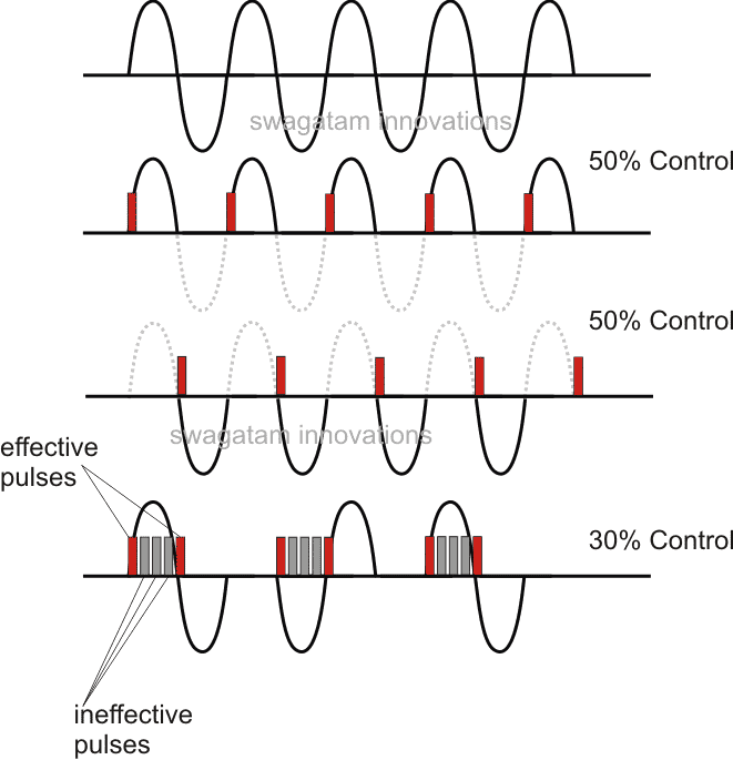
1) The first waveform in the above figure shows a normal 50Hz AC phase signal consisting of a sinusoidal rising and falling 330V peak positive, and negative pulses, with respect to the central zero line. This central zero line is termed as the zero crossing line for the AC phase signals.
The triac can be expected to conduct the shown signal continuously if its gate DC trigger is continuous without breaks.
2) The second figure shows how a triac can be forced to conduct only during positive half cycles in response to its gate triggers (PWM shown in red) at every alternate positive zero crossings of the phase cycles.This results in a 50% phase control.
3) The third figure shows an identical response wherein the pulses are timed to produce alternately at every negative zero crossing of the AC phase, which also results in a 50% phase control for the triac and the load.
However producing such timed PWMs at different calculated zero crossing nodes can be difficult and complex, therefore an easy approach for acquiring any desired proportion of phase control is to employ timed pulse trains as shown in the 4rth figure above.
4) In this figure bursts of 4 PWMs can be seen after every alternate phase cycle which results in around 30% reduction in the triac operation and the same for the connected load.
It may be interesting to notice that here the middle 3nos of pulses are useless or ineffective pulses because after the first pulse the triac gets latched and therefore the middle 3 pulses have no effect on the triac, and the triac continues to conduct until the next zero crossing where it is triggered by the subsequent 5th (last) pulse enabling the triac to latch ON for the next negative cycle. After this as soon as the following zero crossing is reached, the absence of any further PWM inhibits the triac from conducting and it's cut OFF, until the next pulse at the next zero crossing which simply repeats the process for the triac and its phase control operations.
In this way other time-proportional PWM pulse trains can be generated for the triac gate so that different measures of phase control can be implemented as per preference.
In one of our next articles I have explained about a practical circuit for achieving the above discussed triac phase control using time proportional PWM circuit


Questions & Answers
thank you, master for explanation,🙏
Very informative. I am trying to regulate and rectify a 3 phase AC generator which will power a drone and it’s batteries. The problem I have is frequency and voltage is variable, depending on engine speed. Frequency about 1 khz and voltage about 50 v. I need about 5000 watt DC output with voltage limited to 50.4 volts for 12s battery. Would SCR control be best for this goal? Is this power level and frequency realistic for SCRs?
Since the output would be a rectified DC, I would recommend using a MOSFET for controlling the voltage.
Hi,
I am trying to control a treadmill motor using the lower motor control board from the treadmill. I am trying to replace the upper control board with an arduino and potentiometer. The lower board is a triac controlled scr circuit. The lower board outputs a zero crossing square wave to the upper board and returns an scr control pulse. I have created a schematic of the lower board which I could share if needed. I am having difficulty programming my arduino nano to output the needed pulses to trigger the triac. Your description above is very helpful in understanding what is happening but I need some help understanding what is needed from the arduino. If you could help out it would be great!
Hi, thanks, and appreciate your interest….however my Arduino knowledge is still at the newbie’s stage, so it can be difficult for me suggest an appropriate solution for your application. I truly wish I could provide the required help to you.
Hello Sir,
I am looking for best solution for AC dimmer.
I constructed it by Triac-BTA16 but the problem with circuit is it is flickering at very random time.
Frequency is very low, it flicks after 2/3 hours.
Requesting you to do my help.
Thanking you.
Hello Sayyed,
you can the best dimmer circuit in the following article:
https://www.homemade-circuits.com/how-to-make-simplest-triac-flasher/
Thank you
System components
Input devices
Sensor PT 100 to measure the temperature and send it for Processing
Limit switch : the valve now fully open to stop opening command
Limit switch the valve now fully close to stop cloosing command
Output :tow relays one to close the second to open
The system components
Arduino or avr controller
LCD panel & keypad to view actually & set value & to change required temperature value
The system see what is the set value & actually value
For example the temperature need to be higher =1-run command to close relay for one second 2- wait for 30second and remeasure actually temperature if it’s ok
All relays stay off
If not repeat the process untel its achieve the set value
To keep it such as the set value +/-(1c°)tolerance
Sorry, if it’s with Arduino and LCD then it won’t be possible for me!
Thank you alot
Can we do it in another way
Like input method by variable resistor for set value
And the PT 100 also it’s variable resistor change its value by temperature
So if the variable resistor biggest than PT 100 that mean we need to close
If it’s smaller we need to open
Look like comparator circuit put with tow output
OK, you can try the following experimental circuit:
Keep the preset center shaft at the middle.
Then heat the PT100 at 80 degrees, and adjust the preset to just light up the LED
The system is fresh water cooling system
Cooling by sea water via special cooler
Always sea water passing the cooler
We controling in the temperature of fresh water by bypass close or open as the temperature required via motor who controling in the bypass
High flow of water more cooling
Low flow low cooling
The bypass valve not always fully open or close
It’s move partly as temperature required
And to keeping it liner state with the time nearest the setpoint
Great job
I have an idea about project in my mind
I need it for my work
Hot water we need to control in it’s temperature
The sensor who read actually value pt100
Controling in the hest by an electric valve if it open temperature cool down
If the valve close heat up
Put of course if we need the temperature stay liner look like the set value who is need it
The valve or motor who controling in close or open make this condition step by step too keep actually value same the setpoint
For example : setvalue 80° & actually value 70°
The system must close cooling valve 5% and wait 30 second if value not reached close again 5% & wait until reach the set value
I hope this Idea is useful & waiting it to be real
Thank you alot
Thanks, do you mean to say the valve should open at 80 degrees, and close at 70 degrees??
Looking for a phase angle control of triacs for inductive loads, The one available on the net for 3000 Watt control,
application note by SGS Thomson did not work. also getting DB6 is very difficult. if you could make this workable or an alternative circuit would be welcome.
you can try the last circuit, shown in the following article, it will definitely work with inductive loads also.
https://www.homemade-circuits.com/how-to-make-simplest-triac-flasher/
you can eliminate L1/C1 if PFC is not an issue for you…
also make sure to use a triac having in-built snubber such as BTA41/800
What about next articles ?
The 3rd schematic from the following article tries to implement above explained time proportional concept for controlling the speed of a 3 phase induction motor.
https://www.homemade-circuits.com/2016/07/3-phase-induction-motor-speed.html