These smart, intelligent battery charger will charge a Li-IOn battery rapidly by monitoring 3 crucial parameters, which are constant current, constant voltage and constant 25 degrees Celsius temperature.
The post elaborately explains 3 Hi-End, automatic, advanced, single chip CC/CV or constant current, constant voltage 3.7V Li-Ion battery charger circuits, using specialized Hi-End IC TP4056, IC LP2951, IC LM3622, with battery temperature sensing and termination facility.
Design#1
CIRCUIT DESCRIPTION
The first design is probably the smartest one, incorporating the IC TP4056 which is a comprehensive constant-current (CC), constant-voltage (CV) linear battery charger IC specially designed for safely charging single cell lithium-ion batteries.
It comes with a SOP package and hardly any external component count making the IC TP4056 specially applicable for portable Li-Ion charging applications.
In addition, the TP4056 can also work with USB and wall socket based adapter supplies.
This smart design does not depend on any blocking diode due to the presence of an internal PMOSFET architecture which is configured to prevent any sort of negative Charge Current in the Circuit.
A special Thermal feedback loop is included in order to regulate the charge current to limit the body temperature while using in high power operation mode or with high ambient temperatures.
The full charge voltage is fixed at 4.2V, while the charge current can be adjusted externally through a given single resistor.
The IC TP4056 is featured to automatically shut down the charging cycle as soon as the charge current has dropped to 1/10th the set value, after the final float voltage is accomplished.
Some of the other mains features of this IC TP4056 include a built-in current monitor circuitry, an under voltage lockout, an automatic recharge resumption, and a couple of status pinouts to indicate full-charge cut off and the supply input voltage switch ON.
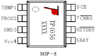
IC TP4056 image and pinout arrangement
FEATURES and SPECIFICATIONS
- Charge Current may be programmed to a max 1000mA
- The circuit can be free of power devices, Sensing Resistor or a Blocking Diode.
- A full fledged Linear Charger in SOP-8 Package for charging applications of Single Cell Lithium-Ion Batteries.
- Designed to Produces a Constant-Current/Constant-Voltage Output
- Capable of Charging Single Cell Li-Ion Batteries through Direct USB Port plugin
- Internally set 4.2V constant Charge Voltage with +/-1.5% Accuracy
- Includes an Automatic Recharge initialization.
- A double LED compatible Charge Status Output Pins for indication purpose
- C/10 Charge Termination or auto shut down feature
- Trickle charge is initiated as soon as a 2.9V threshold is reached.
·An Internal Soft-Start processor Limits and inhibits Inrush surge Current - Comes with a 8-Lead SOP Package, The Radiator needs to be connected to GND.
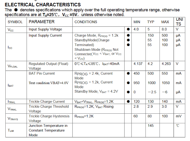
ABSOLUTE MAXIMUM RATINGS
- Input Supply Voltage(VCC):-0.3V~8V ·
- TEMP:-0.3V~10V
- CE:-0.3V~10V
- BAT Short-Circuit Duration:Continuous
- BAT Pin Current:1200mA
- PROG Pin Current:1200uA
- Maximum Junction Temperature:145°C
- Operating Ambient Temperature Range:-40°C~85°C
- Lead Temp.(Soldering, 10sec):260°C
APPLICATIONS
- Cellphones, PDAs, GPS
- Charging Docks and Cradles
- Digital Still Cameras, Portable Devices
- USB Bus-Powered Chargers,Chargers
Pinout specification and functioning details of TP4056 IC
TEMP (Pin 1) :Temperature Sense Input
Hooking up TEMP pin with an NTC thermistor's output in Lithium ion battery pack. If TEMP pin’s voltage falls below 45% or beyond 80% of supply voltage VIN for a minimum 0.15 seconds or more, this indicates that battery’s temperature is simply too high or overly reduced respectively, and charging at this position is stopped. The temperature detection feature could be disabled by joining the TEMP pinto the ground rail.
PROG (Pin 2): is associated with the Constant Charge Current Setting and may be set by attaching a resistor RI(prog) from this pin2 to GND.
While in the precharge mode, the ISET pin’s voltage is regulated to around 0.2V. and in constant charge current mode, the ISET pin’s voltage is regulated to around 2V. Within all modes and in the process of charging, the voltage on ISET pin could be utilized to monitor the charge current through a meter.
GND (Pin3): Ground Terminal
Vcc (Pin 4): Positive Input Supply Voltage
VIN is the power supply input for the internal circuit to operate. Any time VIN falls at around 30mv below the BAT pin voltage, TP4056 goes into low power sleep mode, reducing BAT pin’s current below 2uA.
BAT (Pin5): Battery Connection Pin.
Link the positive terminal of the battery to BAT pin. BAT pin consumes lower than 2uA current whenever the chip is in the disable mode or in sleep mode. BAT pin offers charge current for the connected battery and presents it with a voltage regulation of precise 4.2V.
(Pin6): Open Drain Charge Status Output, Whenever the battery reaches the Charge Termination shut off point, this pinout is dragged low through an in-built switch, but normally this pin remains in high impedance status.
(Pin7): Open Drain Charge Status Output Once the battery is connected and begins charging, this pinout is taken low by an in-built switch, in any other case the pin is held at high impedance condition.
CE (Pin8): Chip Enable Input. A high input here enables the unit to be in the typical operating mode.
Towing the CE pin to a logic low level will force the TP4056 chip into a disable or shut down mode.
The CE pin is compatible and could be associated wit TTL or CMOS logic triggers.
Important Calculations
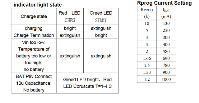
Charge Current Setting (Rprog Calculation):
The TP4056 uses a resistor (Rprog) connected between the PROG pin and ground to set the charge current.
Formula:
Icharge = 1000 / Rprog
Where:
Icharge = Desired battery charge current in milliamps (mA)
Rprog = Resistor value in ohms (Ω)
Example Calculation:
If Icharge = 1A (1000 mA):
Rprog = 1000 / 1000 = 1 kΩ
If Icharge = 500 mA:
Rprog = 1000 / 500 = 2 kΩ
Charging Voltage:
The charging voltage is pre-set at 4.2V which is suitable for all standard 3.7V Li-Ion cells. No configuration is required for this parameter.
Input Voltage Range:
The TP4056 supports an input voltage range of 4.5V to 8V. Please ensure that the power source supplies a stable voltage within this range.
Thermal Regulation:
The IC has an internal thermal regulation feature, in which the charging current automatically reduces if the junction temperature exceeds 120°C. Please make sure to include adequate heat dissipation to get optimal performance.
Battery Full Detection:
The IC stops charging when the battery voltage reaches 4.2V and the charge current drops below 1/10th of the set charge current.
Formula for End-of-Charge Current:
Iend = Icharge / 10
For example:
If Icharge = 1000 mA, then Iend = 100 mA.
If Icharge = 500 mA, then Iend = 50 mA.
Input Capacitor (CIN):
A capacitor is recommended at the input to stabilize the input voltage.
Typical Value:
CIN = 1 μF to 10 μF
Output Capacitor (COUT):
A capacitor is recommended at the output to ensure stable operation.
Typical Value:
COUT = 1 μF to 10 μF
Protection Diode (Optional):
You can use a Schottky diode (DIN) to be placed at the input to protect the IC from reverse polarity or surges.
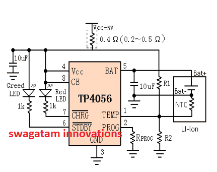
Li-Ion Battery charger circuit using TP4056
The following design represents the typical Li-ion battery charger circuit with constant current and constant voltage features and with auto termination at 4.2V.
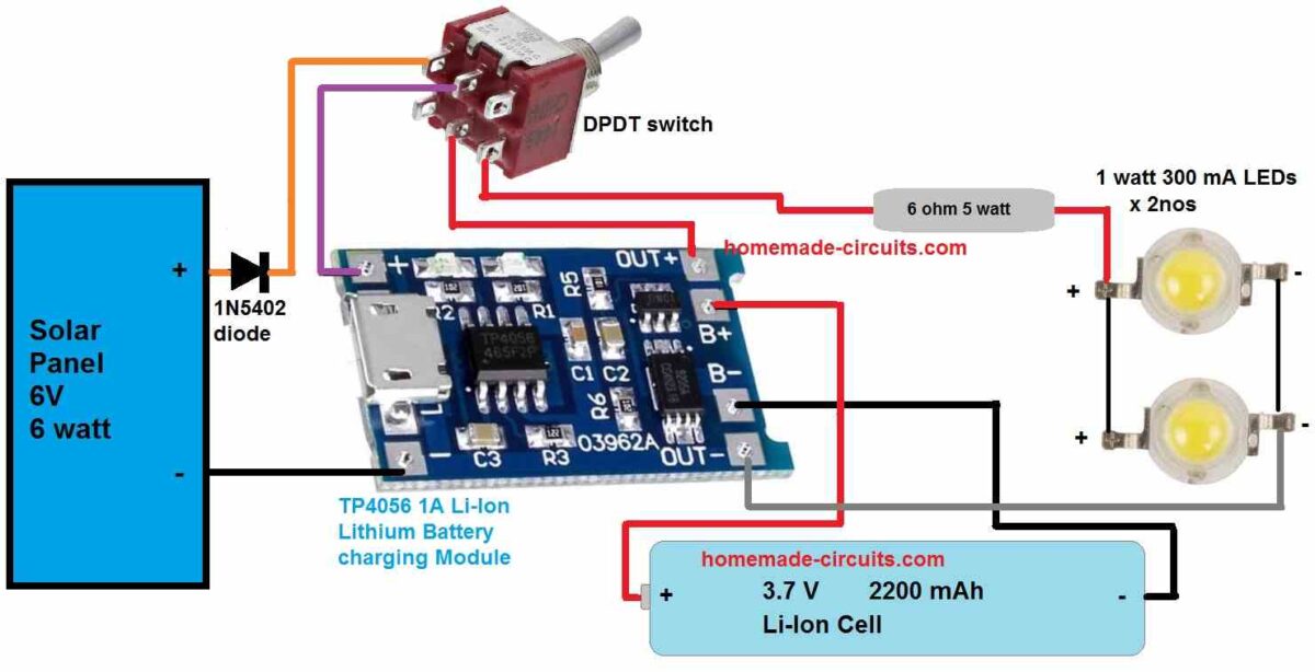
TP4056 Solar Lamp Circuit
The following image shows a highly efficient 2 watt solar LED lamp circuit using the IC TP4056 charger.
This circuit could be used as a vendor solar lamp unit.
The following figure shows the LED status indication details for the above discussed CV, CC Li-Ion battery charger circuit.
Courtesy: NanJing Top Power ASIC Corp.
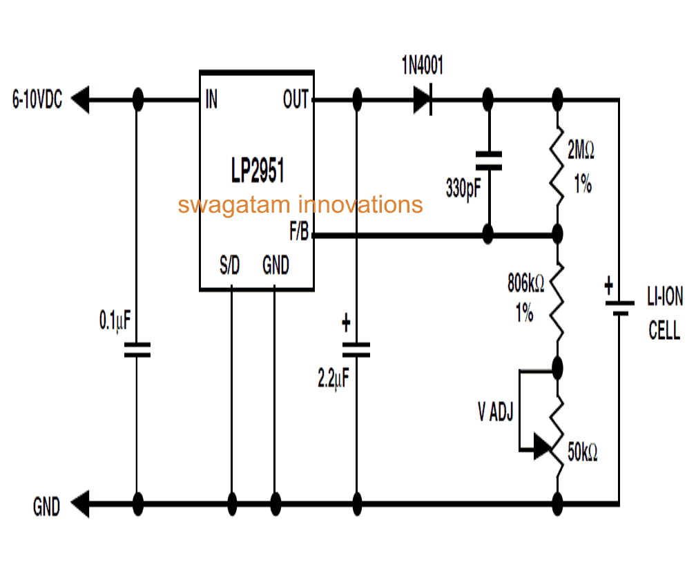
Design#2: Intelligent Li-Ion battery charger using just a single IC LP2951
In this post I have explained a very simple yet safe Li-Ion battery charger circuit using just a single IC LP2951.
Unlike lead acid batteries one good thing about the Li-Ion batteries is that they can be charged at 1C rate initially. It means the charging current may be as high as the rated AH of the battery at the onset.
The design I have I have explained in this article can be used for charging a single 3.7V Li-ion cell or a standard cell phone battery externally at a relatively slower rate.
The diagram depicts a configuration which was used for charging a Li-Ion cell of a portable stereo unit.
The charging specification of the circuit may be summarized as under:
- Maximum charging current = 150mA
- Full charge volt = 4.2V +/- 0.025V
- Charge Current = set at current limit charge mode.
How it Works
In the given circuit the IC LP2951 becomes the main active component which has been specifically chosen because it is capable of delivering an output voltage that's very stable over temperature.
The device also features an in-built current regulation system which limits the output from producing current above the 160mA mark.
Furthermore the IC is entirely short circuit proof and incorporates a thermal shut down facility.
The shown resistor values are precisely selected such that the IC generates an exact 4.2V at its output where the cell is connected.
The trimmer is added for refining the voltage in case there's any discrepancy with the resistor tolerance and ratings.
Initially when the particular discharged cell has a voltage level that's below the 4.2V, the IC generates maximum current to the cell which is around 160mA as discussed above.
This initial current uplift charges the cell rapidly so that it attains the full charge rated value of 4.2V at an earliest.
Once the terminal voltage of the Li-Ion cell reaches the 4.2V mark, the IC LP2951 instantly inhibits the current so that the battery can longer exceed the 4.2 V level.
The above process highlights the ICs constant voltage regulation capability during the charging cycle.
The big value resistors included in the circuit ensures the "OFF" current drain of the battery to below 2mA, the 330pF capacitor stabilizes the circuit from unwanted noises created at the high-impedance feedback node.
The diode at the output is obviously for preventing the back flow of the battery voltage into the IC in the absence of input voltage.
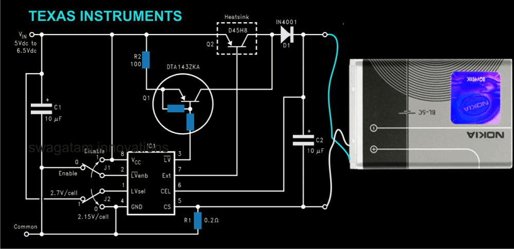
Design#3: Another Efficient Charger for Li-Ion using IC LM3622
Here we discus a current controlled Li-ion battery charger circuit which has been specifically designed for charging all types Li-Ion Batteries very safely and without any considerations.
It is generally advised that a Li-ion battery should be charged with utmost care and caution as these type of batteries are prone to instant damages or explosions if the specified charging measures are not employed.
Thanks to TEXAS INSTRUMENTS for providing us with this wonderful chip, the LM3622 which is an excellent Li-Ion charger, controller device.
How the Circuit Functions
The IC has been designed for generating a constant current at constant voltage, a basic prerequisite for all Li-Ion batteries. The IC may be configured for charging a single Li-Ion cell or a pack of many.
The circuit using the IC LM3622 can be fed with voltages right from 5 to 24V depending upon the charging needs and the connected battery.
The IC does not require any precision external resistors for implementing the functions. Moreover, the IC has a negligible drain of less than 200nA of current from the battery in the absence of an input voltage.
The in built circuitry of the chip accurately regulates the charging current through the principle of temperature compensated band-gap reference.
The current is regulated, however its done via an external current sensing resistor.The band gap principle results in an efficient operating control performance of the circuit and also of the input supply voltage.
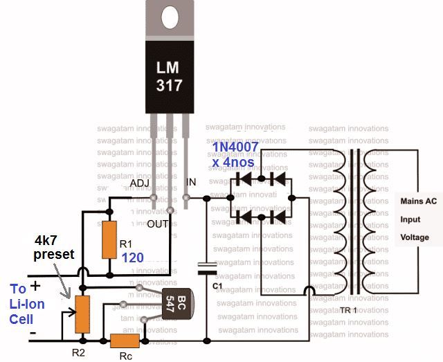
The shown current controlled Li-Ion battery charger circuit illustrates a low drop out linear Li-Ion battery charger design which is capable of charging a single 3.7V Li-Ion Cell.
For enabling low voltage detection, the switches J1 and J2 may be appropriately selected.The IC starts the charging process by first detecting the voltage of the cell and “enable status” of the low voltage detection.
The transistor Q2 immediately comes into the operating condition as soon as the connected battery hits target regulation level, determined by the internal setting of the IC.Q2 now begins supplying a regulated voltage to the connected battery, initiating a constant voltage charging mode of the circuit.
In the above situation the battery receives a constant regulated voltage across its terminals, while the charging current is monitored depending upon the level of charge over the battery. On reaching a full charge condition, the charge current to the battery is significantly reduced to a safe value.
Smart Li-Ion Battery Charger Circuit Diagram using IC LM3622
These were the assorted top 3 smart, intelligent Li-Ion Battery charger circuits for you, if you any more ideas or information regrading such smart designs, please feel free to express them through comments.

Comments (60)
Hi Swagatam,
Does the LP2951 cut’s off the charging process upon completion, after the battery is fully charged?
Hi Nelio,
Yes the LP2951 cuts off the charging process as soon as the battery voltage has reached 4.2 V.
Ok. Thanks.
Regretably LM3622 is no longer manufactered and LP2951 doesn’t have a LED to monitor charging process…
Nélio Abreu
Yes that’s unfortunately true.
Dear sir,
Please sir, help me with the circuit for smart/android phone charger (5V 2A)
Hi Godfrey, you can try the concept presented in the following article:
https://www.homemade-circuits.com/220v-smps-cell-phone-charger-circuit/
The second circuit using LP2951 does NOT working!
Sir, please I need li-ion battery charger circuit diagram that can charge 7.4v 2A li-ion battery with Auto cut- off and current controller .
E mail: thankgodchikere8@gmail.com
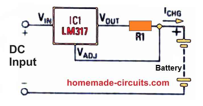
Hello ThankGod, no need of an auto cut off, you can simply use an LM317 constant current constant voltage power supply, adjust the output to slightly below the full charge level, in your case it will be 8.2V (8.4V being the maximum charging level). here’s the circuit diagram you can use:
Full details is given in the following article:
https://www.homemade-circuits.com/simplest-safest-li-ion-battery-charger/
Hello Swagtum,
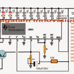
It was really informative reading your blog. We need to design a charger that will have two charging pots/Bay and may charge one or two batteries at the same time depending upon the ease of user. And also there should be three indications in the design. One for power input: Green LED which should turn on as soon as power is connected, and other two for charging pot/slot (one for each) showing the battery charge status. The indication system for each charging slot will have three LEDs one for 0-50% charge other for 50-75% charge and the third one when the battery is fully charged.
we already have a charger but the charge status indication mechanism for that charger is not that much accurate and we receive complaints from our clients
Hi Qasim, you can try the concept explained in the following article;
https://www.homemade-circuits.com/3-step-dc-voltage-level-monitor/
Sir the first circuit is for Lithium ion Cell but what id i wan to charge a 12v 14Ah Lithium ion battery?
Then this circuit would work?
What are the limitations or what changes or circuit should i choose to charge a 12v 14ah Lithium ion battery.
Thnanks
Thanks for the quick update. I would like to tell you that we are already doing so by using LM358. But the problem is when the battery is near to full charge or above 3.8V and the battery connection with the charging pins is disturbed every time there is difference in battery voltage sometime it is read 3.9V sometime 4.0 and sometime 4.1 at the same time. so at this moment indication is not stable like once you removed the battery from charging and it is 3.9V, red indication showing the battery is under charging, at that very moment you again connect the battery and the voltage may be read as 4.0 or 4.1V showing the battery is full giving green indication.
So this less precise indication is the problem like at the same time it is red and at that time after disconnecting and connecting again it turns green. this is the problem and we want to get rid of it. I was looking for an IC package that have all the desired functions for charging li-ion/li-po batteries along with indication mechanism.
Thanks Qasim, all op amps are extremely accurate with their switching provided the preset or the variable resistor connected witht their input pin is highly stable and accurate, and also the supply voltage is constant.
You can try multiturn preset for better accuracy, or try using fixed resistors instead of preset.
Hey Swagatam,
I am Raj and I want to design a circuit to charge 18650 battery (3p configuration). Each battery has a capacity of 3300mAh, so a total of 9900mAh. I have a 30-watt mobile phone Charger rated at 5volt and max of 6amp. So, I am willing to fast charge a 36wH battery with a 30watt charger. I am a first-year grad in Mechatronics Engineering and don’t have much knowledge in electronic circuit design. After doing research about LM138 and LM338 IC by Texas Instruments, they are capable of handling 5Amp of current through them. I would be grateful If you can help me design this circuit.
Hi Raj, yes you can use LM338, but you will need a large heatsink to ensure proper working of the unit. Also you may have to monitor the battery temperature, if you find its temperature is going above 45 degrees Celsius, then you may have to install a small fan near the battery for air cooling.
You can try the fist circuit from this article:
https://www.homemade-circuits.com/ic-lm338-application-circuits-explained/
Adjust the pot such that the output is slightly lower the battery’s full charge limit, that is 4.1 V
Hi, i have a circuit with 4056 IC to charge 3.7 volts lion battery. Actually there is 0 voltage on both battery terminals and even no voltage on IC Batt Pin out. What will be the reason?
How to confirm that IC is bad? Can i replace the IC with new.
Hi, if you have connected everything correctly and still no response, then you can try changing the IC and see if tat helps!
Thank you sir
Actually I am not sure if 16v is the full charge level of the battry.all i know is the whole package is 12v at diff connection with high pwr and current.The 16v is input to battery regltor circuit & the circuit opt to battry terminal.
Moreover, is it only LM388 and variable resistor should I connect btw solar panel and the battery input regulator? And then,100W 5A with 19v short circuit panel can work.?
Best regard!
Alee, if you are not sure about the full charge level, then you should not use the previous idea, instead yo can try a current detected cut off, as explained in the first schematic from this article. You may adjust the output to 16V, and calculate the current limit resistor for 3 amps
https://www.homemade-circuits.com/battery-current-indicator-circuit/
Hello sir.
I would like to help me out on how to charge my PC external battery using solar panel.Is a 40piecs lithium iron battery package in black with 16V 4.5A input and 2 output of 19v &30v respectively.it takes at least 7hr to fully charged using power supply.
How can I charge it with solar system.
My email,johnfoul8@gmail.com
God bless you!
Hello Alee, if you are sure that 16 V is the full charge level input for the battery then you can use an LM338 based regulator and adjust its output voltage to 15.9 V. For the solar input use a 24 V 5 amp solar panel, and feed the supply to the LM338 input
hi sir.
could you design me a circuit charger that can charge 3 cells of 18650 battery with multistage current charging method? thank you, sir.
Hi Geo, I’ll try to do it soon. It will be based on the following concept:
https://www.homemade-circuits.com/make-this-3-step-automatic-battery/
thank sir.
appreciate it.
Buenas noches… gracias por su pagina tan interesante, sobre todo para los que solo somos aficionados a la electrónica. estoy interesado en un cargador para pequeñas baterías de 3.7 V a 200mAh en adelante, hasta unos 4.8 V. quedo a la expectativa por su ayuda y muchas gracias.
Thank you William, I think you should try the following concept:
https://www.homemade-circuits.com/usb-automatic-li-ion-battery-charger/
This can be used for charging all types of Li-Ion with ultimate safety and perfection.
circuit works on a 7.2 np-fm500h battery?
what is the Ah value?
it does not have Ah i has Wh so watt hours. it has 11.8Wh
It can be probably converted to Ah by dividing the value with 7, however these are all 3.7V chargers, so I think a 7V battery cannot be charged with these units.
Instead you can apply this one:
https://www.homemade-circuits.com/usb-automatic-li-ion-battery-charger/
I also would like to use the pin 1, temp sense capability, using a 10k type 2 NTC thermistor, but seem to have problems with the R1,R2 values to get proper temp tracking setup.
Please refer to the comment discussion with ABBA
Hi there! I want to use this IC in my DIY powerbank. How many 18650 cells can I charge with this board? Is there any difference how many cells do I connect to it?.. Thanks a lot, keep up the great work.
Hi, Thanks for posting the question, You can charge only one cell with this circuit.
Great circuits. I have cells rated at 3.7Volts. Could you use this by including a small voltage regulator from say 4 down to 3.7 volts between pin 5 and the cell?
A 3.7V cell will require a 4.2V input and will need to be charged until it reaches a full charge level of 4.2V, so this circuit can be used directly with your 3.7V cells without any modifications.
Thanks Kevin, I am glad you liked it!
Hello Bro,
How can i make cutt-off circuit for load cutt-off when charging battery?
Please suggest me circuit using n-channel or p-channel mosfet.
When i connect battery charger for charging it should disconnect load from battery and when i remove charger it should connect the load to battery.
Thanks
Bro, the circuit will automatically disconnect the charger and connect the load with the battery, so removing the charger will not be necessary.
you can try the following concept
https://www.homemade-circuits.com/universal-battery-charger-circuit-with/
you can replace the BJTs with mosfets
Bro this wasn’t i meant.
I made emergency light.
It should automatically turn on when electricity is not available (means during load shedding hours) and should turn off when electricity is available.
I used to accomplish this using mechanical relay.
But now I can’t get 5v relays easily. So please suggest me NO and NC solid state relay circuit. I want to replace mechanical relay using mosfets.
Thanks
without schematic it will be difficulty for me to give the solution.
however here’s one idea that you can refer to
https://www.homemade-circuits.com/12v-dc-solid-state-relay-ssr-100-amps/
This is the right circuit i wanted. NC and NO SSR using mosfets
Thanks
OK great, wish you all the best!!
hi Swagatam, i can’t find the value of R1,R2 and NTC
Hi Abba, I too could not find any reference to it in the article, as well as in the datasheet.
However from the placement of R1, R2 it clearly seems that those are positioned to set the battery temperature sensing threshold.
You can experiment it by using 4k7 for R1 and a 10K preset for R2, this preset can be tweaked to identify and set the battery temperature sensing and cut-off threshold point.
hi swagatam i can’t find the value of R1 and R2 AND NTC. THANKS
Hi, I’ve built a charger project using the TP4056 and it works fine but when it reaches 4.06v it stops charging, the red light stays on, I’ve got a heat sink on top of the chip with non conductive thermal tape and the board sits on a piece of veroboard securing the wires and heatsink, there’s a 7seg LED voltmeter in parallel to the battery and an LED with 300 ohm as the LED was quite bright. If I switch charge off at 4.06v then back on the TP’s blue LED will come on. The 5v supply is fine, could it be the voltmeter or wiring maybe, thought I’d ask someone in the know before taking it apart ? Thanks
Hi, It seems the IC is functioning but instead of 4.2V it is switching OFF at 4.06, which looks like an internal issue with the IC, I don’t think it is due to the voltmeter, but it is better to verify the same by removing the voltmeter and connecting it only after the red lED lights up.
and is the IC getting too much warm? If it is then make sure to attach the heatsink firmly with the IC, and use ample heatsink compound paste between the two.
Hi Joshi,
you can try the concept which is shown in the following article:
https://www.homemade-circuits.com/2011/12/high-current-10-to-20-amp-automatic.html