In this post, I will show how to construct an Arduino based battery level indicator, where a series of 6 LEDs show the level of the battery. If you are interested in monitoring and maintenance of your 12V battery, this circuit might become handy.
Why Battery Level Monitoring is Crucial
All batteries have certain voltage limit to discharge, if it goes beyond the prescribed limit, the life span of the battery will reduce drastically.
Being electronics enthusiasts, we all might have a battery for testing our prototype circuits. Since we concentrate on the prototype during experiment, we care less on the battery.
The proposed battery charger circuit will show you how much energy left in the battery, this circuit may be connected to battery, while you prototyping your circuits. When this circuit indicates low battery, you may put the battery to charge. The circuit has 6 LEDs, one LED glow at a time to indicate the voltage level of the battery.
If your battery is full, the left most LED glows and you battery is dead or about to die, the right most LED glows.
How it Works
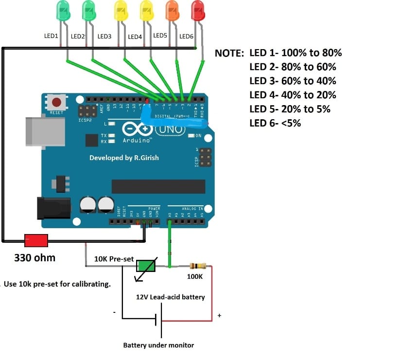
The circuit consists of Arduino which is the brain of the system, a potential divider which helps the Arduino to sample the input voltage. A pre-set resistor is used to calibrate the above setup. The series of 6 LEDs will indicate the battery level.
Calibrating LED Indicators
The relation between LED and battery level is given below:
LED1 – 100% to 80%
LED2 – 80% to 60%
LED3 – 60% to 40%
LED4 – 40% to 20%
LED5 – 20% to 5%
LED6 - <5% (charge your battery)
The Arduino measures a narrow range of voltage from 12.70V to 11.90V. A fully charged battery should have voltage above 12.70V after disconnecting from charger. A low battery voltage must not go below 11.90V for a 12V sealed lead-acid battery.
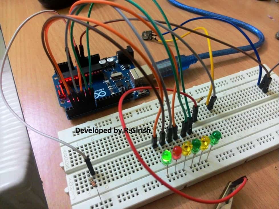
Author’s prototype:
Program Code:
//--------Program developed by R.Girish---------//

int analogInput = 0;

int f=2;

int e=3;

int d=4;

int c=5;

int b=6;

int a=7;

int s=13;

float vout = 0.0;

float vin = 0.0;

float R1 = 100000;

float R2 = 10000;

int value = 0;

void setup()

{

Serial.begin(9600);

pinMode(analogInput,INPUT);

pinMode(s,OUTPUT);

pinMode(a,OUTPUT);

pinMode(b,OUTPUT);

pinMode(c,OUTPUT);

pinMode(d,OUTPUT);

pinMode(e,OUTPUT);

pinMode(f,OUTPUT);

digitalWrite(s,LOW);

digitalWrite(a,HIGH);

delay(500);

digitalWrite(b,HIGH);

delay(500);

digitalWrite(c,HIGH);

delay(500);

digitalWrite(d,HIGH);

delay(500);

digitalWrite(e,HIGH);

delay(500);

digitalWrite(f,HIGH);

delay(500);

digitalWrite(a,LOW);

digitalWrite(b,LOW);

digitalWrite(c,LOW);

digitalWrite(d,LOW);

digitalWrite(e,LOW);

digitalWrite(f,LOW);

}

void loop()

{

value = analogRead(analogInput);

vout = (value * 5.0) / 1024;

vin = vout / (R2/(R1+R2));

Serial.println("Input Voltage = ");

Serial.println(vin);

if(vin>12.46) {digitalWrite(a,HIGH);}

else { digitalWrite(a,LOW);}

if(vin<=12.46 && vin>12.28) {digitalWrite(b,HIGH);}

else { digitalWrite(b,LOW);}

if(vin<=12.28 && vin>12.12) {digitalWrite(c,HIGH);}

else { digitalWrite(c,LOW);}

if(vin<=12.12 && vin>11.98) {digitalWrite(d,HIGH);}

else { digitalWrite(d,LOW);}

if(vin<=11.98 && vin>11.90){digitalWrite(e,HIGH);}

else {digitalWrite(e,LOW);}

if(vin<=11.90) {digitalWrite(f,HIGH);}

else {digitalWrite(f,LOW);}

delay(2000);

}

//--------Program developed by R.Girish---------//
How to Setup the circuit:
The calibration for this Arduino 6 LED battery level indicator circuit must be done carefully, if you did not calibrate correctly, the circuit will show incorrect voltage level of the battery.
When you turn on the circuit, it starts with LED test, where the LEDs glow up sequentially with some delay. This might help you to debug errors while arranging the LEDs.
1) Set the voltage of your variable power supply to precisely to 12.50V.
2) Open the serial monitor.
3) Rotate the preset resistor clock wise or counter clock wise and bring the readings to 12.50V.
4) Now, reduce the variable power supply to 12.00V, the readings on the serial monitor should show the same or very close to 12.00V
5) Now, increase the voltage to 13.00V, the readings on serial monitor should also show the same or very close.
6) At the same time when you increase or decrease the voltage, the each LED should turn on/off with different voltage levels.
Once the above steps are done successfully, your battery level indicator circuit will be ready to serve the intended purpose.
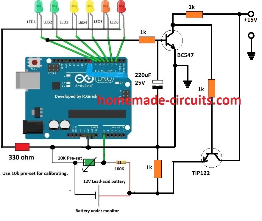
Adding an Auto Cut Off
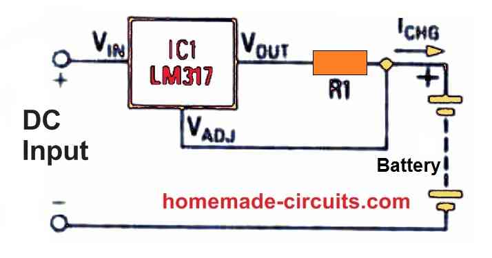
The above explained Arduino battery level indicator circuit can be further enhanced by including an automatic battery full charge cut-off facility.
The following figure shows how this may be implemented in the existing design:


Questions & Answers
Dear Sir
i have 90000 mah ,5v capacity PB & Google Pixel 7a model mobile.
i want to make switcher kit . when Battery goes below 80% level then switcher start and power bank voltage goes to mobile phone battery & when Mobile battery goes 100% it cutoff.
i want to use mcu but facing hardware problem for proper design what to do ,can u please guide how can mcu & which mosfet work proper.? i have also idea about adc level. So i first detect 80% level with help of resister divider network as a ref level of 80 to 100% & that voltage fed to mcu adc pin . but from mcu to mosfet switching for control i have less idea of good choice ckt
Dear
can we check mobile battery level ( volt )on TYPE C pin without connect charger? i want to use that volt as a ref so in application.
Nitesh, Frankly i have no idea about it, however my guess is, that may not be possible.
Dear Sir.
Yes it not possible . Mobile mfg did not give us direct bat ref voltage on C pin . we must be design mobile bluethooth app & control .Via this methode may be
Yes Nitesh, you are right, unfortunately that is not possible.
Hi Nitesh,
Sorry, Unfortunately my knowledge of Arduino is also not good, so programming the code may not be possible for me too!!
Dear Sir
ok Thanks
Sir agar mujhe led 48 volt or 60 volt se operate Krna ho toh uska programe or stecmatric kya hoga
M cahata hu bettry jb ki bettry 48 volt ki h
Current 42 pr red bettry
48 volt tak full green ho jaye
Konsa micro controller use kre
Jaiprakash,
Since I am not good with Arduino I am not sure whether the above circuit can be used with a 48V battery or not.
Why don’t to try an analogue circuit using an IC such as LM324, it would be much easier to assemble and the results would be fail proof.
Hi… please can u post a video of this circuit functioning.. i find it difficult to install to my project
Please tell me, will it work for 96V Battery system. If yes please suggest the changes need to be done.. It is very helpful for me..
I won’t recommend this circuit for monitoring a 96V battery
Hi Swagatam
Do you suggest monitoring a 48 V battery?
Hi Alamgir, I do not recommend 48V charging for the above concept.
hello sir, satya here can you send me the solar powered mobile power bank system connected to loads….circuit diagram using arduino i’m waiting for your best reply
Hello Satya, I am not an Arduino expert so I can’t help you with Arduino related projects.
Hello sir. My name is Nurlina.
I have a question.
What is the purpose of the 10k preset resistor? (sorry i just started learning this).
and i wish to use this circuit for a 3.7v li-ion battery with a capacity of 20000mAh, which part of the coding should i alter in order for my circuit to function well?
Hello Nurlina, The perset is for calibrating the LEDs so that they the exact reading for the different voltage levels.
Sorry, regarding the coding I do not have much ideas!
thank you for answering my first question, but i actually have a few more to ask.
1) what is the function of 100K resistor?
2) can i use 320ohm resistor instead for the led if i dont have any 330ohm?
3) why did u set different voltage value during calibration for the led from the one you write in you program?
The 100k is for forming a potential divider with the 10k preset for feeding a voltage reference level to the specific Arduino pin
320 ohm will also work
The article was written by another author, so I cannot suggest much on the corrections. You must build it and test it practically to learn the precise working of the circuit
Hi Swagatam, thank you for your battery level indicator. I want to use this with a tweak. I don’t know how to write the program but I need if for a 9 volt battery and I need it to work with 5 LED’s. I also need the LED’s to be able to dim with a potentiometer from 100% bright to 0% (completely dark). One last thing, I wonder if this can work with Arduino Nano. That would be even better. Do you think you can help me with that? I will be eternally grateful. Keep up the good work.
Hello I’ve question, can it use to charge mobile phone by adding USB adapter? Or just only the battery?
Thank you Tyler, however, my Arduino knowledge is also not good enough, so I won’t be able to guide you with the required code modifications, and related info!!
Hello sir,
I’m Swaraj Chavan.
I have a question???
What is the role of 330ohm resistance in the circuit??
Swaraj, it is to protect the LEDs from over current.
Thank you!
Can you suggest me battery Level indicator circuit for 3.7v 2.6Ah lithium ion battery cell??
Project detail :- We have made a charging station project for electric bikes.
In this project we develop a battery charging circuit.
This is a prototype project. we used Li-Ion( 3.7v , 2.6Ah ) batteries. Can we use Arduino Uno to protect the battery from overcharging ? Or
Can we use Arduino Uno to show how much battery is charged?
When the battery is fully charged, the battery will automatically disconnect from supply with the help of Arduino Uno. Whether this is possible or not by using Arduino Uno.
Please suggest us right way..
You can try the same circuit which is explained in the above article, just replace the battery with your 3.7V li-ion, and replace the supply input with 6V 1 amp charging supply. Make sure to provide the Arduino with a separate 5 V supply.
For auto cut you can use the last updated design
Thank you
hi sir,
Instead of led can we use an LCD to display the percentage of battery charge and also can we make automatically control the Charging of battery like if it’s become 100% automatically stop of charging and when it becomes 10% it as to start charging .
Hi Abhi, I am not good with Arduino coding, so I do not have much idea about LCD integration. For automatic battery cut off the respective LED stages can be configured with a relay driver stage for the required operations
Sir this circuit possible to measure battery life of 12V lithium or li-ion batteries
Yes it can be used for measuring the battery LEVEL of any 12 V battery
Sir, is it possible if you want to read the voltage of 2 separate batteries simultaneously with Arduino?
Anwar, sorry I am not very sure about it!
okay sir, thank you for your answer
sir i intend to construct a battery percentage monitor for a led lamp. how possible is this and how can i go about it?
You can use the same circuit which is explained above for your application
Sir can I use the nrf module codes and this codes in the same arduino
Sorry Vysakh, I have no idea about it.
Hi sir! dear sir i want to add hysteresis feature to this battery monitor so that battery upper threshold level (cut off point) = 14.4v, lower threshold level(charging start point) = 12v by adding a relay to a battery charger with the same led display using arduino. my problem is what to do with the code to add hysteresis feature so that when the battery full it my not start charging until it reach back to 12v?
Hi Sheraz, actually code modification may not be required, it could be easily done through an external opamp circuit, if possible I’ll try to update it soon….
Hy mr.Swagatam
i have home work to do project about controller baterry/automatic charging using Arduino Uno,MOSFET/Transistor and Voltage sensor…
i’m still confuged in arduino program code during charger and dischsarge….
may you help me…
Hi Melchior, the above circuit can be easily converted into an auto cut-off system by integrating a mosfet stage with the appropriately selected outputs from the Arduino.
Let me know if you want me to do this modification in the above circuit??
Thank you so much for your help…
I tried the program first …
if there is still a problem I will consult again with you …
once again
thank you very much for your kindness, have helped me
OK, no problem!