The TL783 is a variable three lead mains voltage regulator chip having an output range of 1.25 V to 125 V and a DMOS output transistor which is able to handle in excess of 700 mA current.
High Voltage Specification
It is specifically configured internally for working with high-voltage applications where ordinary bipolar voltage regulators become useless.
High grade performance specifications, much enhanced than most bipolar regulators are implemented through a hi-breed circuit network and sophisticated layout technology.
In this innovative regulator device, the TL783 integrates the standard bipolar circuit technology with high-voltage double-diffused MOS transistors on one chip, to create a device attributed with properties for enduring higher voltages far higher than traditional 78XX bipolar integrated circuits.
Due to the inability of secondary-breakdown and thermal-runaway situations inherently common with bipolar devices these become quite vulnerable to high voltages, unlike these the TL783 ensures full overload protection even under extreme operating conditions ranging up to 125 V across input to output.
Built-in Current Limiter
The chip also includes an in-built current limiting feature, a safe operating area safeguard and also a thermal shutdown feature.
In a worst case even if the ADJ gets isolated accidentally, all the above protection features stay functional.
The IC can be initiated and made functional just by adding a couple of external passive components. An input bypass capacitor becomes only essential in case the DC supply source is fetched from beyond 6 inches from the IC.
The IC also exhibits excellent response to sudden output short circuits and sudden voltage spikes or transients.
Circuit Diagram
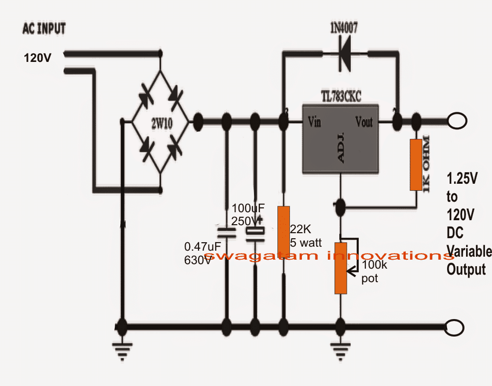
WARNING: PLEASE REMOVE THE 100uF/250 CAPACITOR FROM THE INDICATED POSITION AND PLACE IT ACROSS THE OUTPUT TERMINALS OF THE CIRCUIT, THIS WILL ENSURE THAT THE 120V INPUT DOESN'T GET TRANSFORMED INTO A DANGEROUS 160V PEAK AND DAMAGE THE IC.
THE GROUND SYMBOLS SHOWN WITH THE NEGATIVE LINE OF THE ABOVE CIRCUIT SHOULD NOT BE MISTAKEN WITH "EARTHING" OF THE 3-PIN SOCKET. THE GROUND SYMBOLS ARE ONLY FOR HIGHLIGHTING THE NEGATIVE LINE OF THE BRIDGE RECTIFIER.
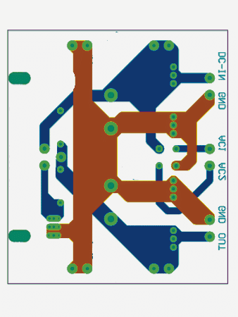
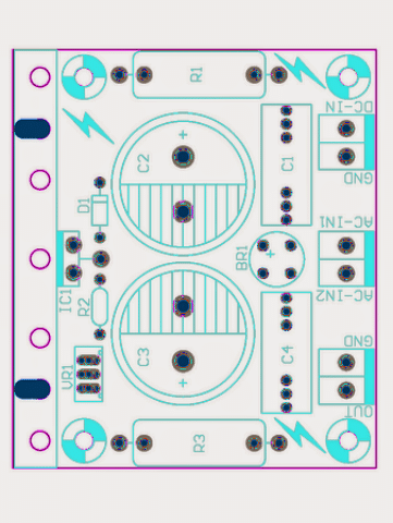
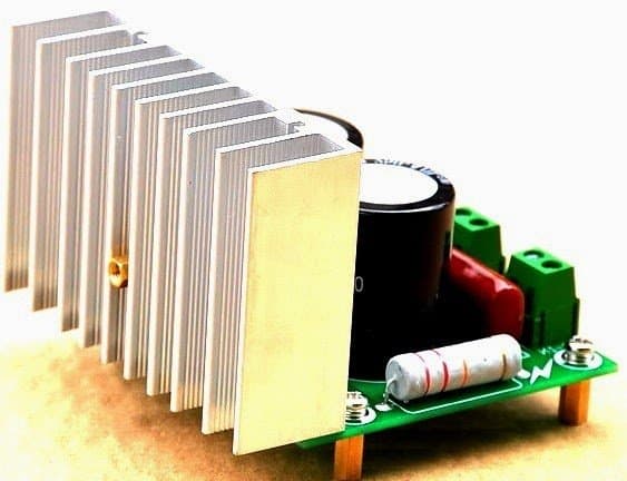
CAUTION: THIS CIRCUIT IS NOT ISOLATED FROM MAINS AND THEREFORE IS EXTREMELY DANGEROUS TO TOUCH WHILE POWERED AND IN AN UNCOVERED SITUATION.


Questions & Answers
6v4.5ah Led driver7805 wich hour 1w 2led bulb on.
Battery power=> 6v*4.5ah=27wh. The two LEDs must be in parallel, therefor, their voltage will be 3v, while their current will add up. Since the power of one LED is 1watt, with 3v, its current will be taken care of by joule's law(I=P/V). Ie, 1/3=0.3333A. So, for the two in parallel, it will be 2*0.3333A=0.6666A. So, the power of the two 1 watt LEDs in parallel will be 0.6666*3=1.9998w(i.e, P=iv). So how long it will last in hours is given by: Battery power/LEDs power => 27wh/1.9998w=13.5h(0.56 day, or half a day plus). Hope it helped?
The PCB shows 4 capacitors, yet the schematic only show 2. Clarify?
It was posted a long time back, so I am having difficulty in remembering the details, if you can point out exactly at what point in the diagram the extra resistor is been introduced I may figure out if it's really crucial
what is the maximum voltage that can be given to the terminal Vin.
around 160V
sir what we have to do to make it work on 240vAC input?
asif, It's not possible with this design, there's no such feature in this IC
hello sir..
what is the wattage of Preset. ?
and 1k resistors. ?
does its out put can be verified by using any formula ?
hello lokesh, the preset is a standard type which are normally used in ordinary circuits…..the 1K can be a 1/4 watt resistor
you can refer to the datasheet and check if there's a formula for it
I wish to make 230vac in 110vdc out with 5amps
so is it practically possible if I connect TL783. 7ic parallel in single heat sink all ics out put shorted after capable diodes.. With 5amp transformer plz let me know the possibility
thank you
No it's not feasible because the input is specified at 120V..therefore 230V cannot be used
thank u
for reply sir
presently paralleling of TL783 being connected along with suitable Diode
(4ic)X(700mA)= 2800mA theoretically
but tested till 200mA running fine
i dont want to take risk so haven't went for further test..
thank u
for reply sir
presently paralleling of TL783 being connected along with suitable Diode
(4ic)X(700mA)= 2800mA theoretically
but tested till 200mA running fine
i dont want to take risk so haven't went for further test..
forgotten to metioned that 230in 110vac out Transformer being used at input of TL783
you have used a transformer also, in that case what's the need of TL783, you could simply use a MJE13005 emitter-follower circuit for getting a variable 0 to 110V output
thank u for suggestion i have Question on this
1) is That MJE13005 emitter-follower circuit will support till 110VDC 5amps?
2) single Ic is enough?
3) What is advantage against TL783?
4) May i have circuit diagram?
5) is it locally available for cheep?
6) is it Free of harmonics and have short circuit protection?
i hope you have answers for this sir
Thank you
in Advance
1) it will not support 5 amps, your present circuit is supporting only 200mA.
2) MJE13005 is a BJT, a single will be enough for the voltage control
3) it will offer current than TL783, and the parts are easily available.
you can try the following concept, replace the mosfet with MJE, and reduce the 560K to 10K, 5 watt
5) yes.
6) you can add a filter capacitor at the output for ripple control…the second transistor in the diagram will control the current.
make sure to use your 220V to 110V transformer with the above proposed circuit.
…sorry here's the link
https://www.homemade-circuits.com/2013/06/0-300v-variable-voltage-current.html
Hi, I built the circuit 3 times, but my 100k potentiometer keeps blowing up!
It is 0.4Watts.
Any advice?
Thanks
David
Hi David, if your input supply is 110V and still the the pot is burning then definitely your IC is faulty or is a duplicate qulity… or you might have done something wrong initially which might have blown the IC.
the pot will burn only if an abnormally large current flows through it, which can happen only if the iC itself is malfunctioning.
Hi,
Thanks for your help.
I've investigated further…..
I am in the UK and using a 230V to 120V Transformer (50W).
The output of the Tx is 118V RMS, which the BR coverts to converts to 115V DC as measured by my voltmeter.
Applying the capacitor on the input side of the Regulator pushes the voltage on Vin of the TL783 (as measured on my voltmeter) to 160V DC. I now understand that this is due to the fact that the capacitor stores the peak voltage so is 1.4 x 115 = 160V.
Do you think that this is blowing the regulator (as it is stated in the datasheet that the voltage in Vin should not exceed 125V).
Thanks
David
Yes you are right, your IC got damaged due to the 160V since it is not rated to handle more than 125V peak.
Hi,
Thanks again for your diagram and your feedback on my comments.
Reducing the input electrolytic capacitor to 1uF (rather than 10uF) reduces the overvoltage (160V) at Vin problem. I now have Vin at 115V DC and all works fine.
The Output safely varies from 4V to 110V DC, which is what I wanted.
Might be worth making this change to your diagram (to show 1uF instead of 10uF) or instead identifying that the AC input if 120V is Vpk, not Vrms, else people might blow their IC's and potentiometers (like I did)! No worries my friend.
Thanks again and best regards.
David
Thanks David, I am glad you could solve the problem so simply… I'll put a notification under the diagram soon
CAUTION: THIS CIRCUIT IS NOT ISOLATED FROM MAINS AND THEREFORE IS EXTREMELY DANGEROUS TO TOUCH WHILE POWERED AND IN AN UNCOVERED SITUATION.
The caution note is helpful but you show a ground symbol on tour schematic. One must not interpret this as an earth ground. If one connected this point to the ground or neutral point on the mains circuit it would be a disaster. One is tempted to use full wave bridges because of their simplicity but unless isolated they are inherently dangerous.
Thank you for your suggestion, I have attached a second warning message just under the diagram addressing the issue and clarifying its significance.
Dear Sir,
I need more a little bit more power on it,
As can supply more than 10A,
Please your advise
Thanks and regards
Dear Martin, for higher current you may have to put an outboard P channel MOSFET across the IC with some calculations
Hi sir, Shaan here, Hope you are fine by grace of god. I need your help, is there any circuit to regulate 100v AC voltage to desired AC voltage (AC-AC stepdown controller)? If any idea then plz do share with me. Thanks in advance..
Hi Sir,
If it's an SMPS type of regulator you are looking for, then I think you could try the following one:
https://www.homemade-circuits.com/2017/07/110v-14v-5v-smps-circuit.html
Prezado, voce poderia me informar um circuito que ajusta tensão e corrente DC +- 120VCC – até 1A ? Obrigado
Hi, you can try the designs explained in the following article for getting a dual 120V adjustable outputs, however you will have to first upgrade the transistor ratings to around 200V 5 amps.
Good day your design 1.25 to120 volt dc variable output will be perfect for what I want to do but I need to change it to 230 volt for I need to is 63 volt for anodizing to get bronze to gold colour can you help me pls
Good day, I understand, you need to work with a 230V input AC, but that is not feasible with the above concept.
Instead you can try the 2nd circuit from the following article:
https://www.homemade-circuits.com/0-300v-variable-voltage-current/
Let me know if you have any further questions…