The proposed 00-99 digital pulse counter circuit becomes very handy in places where you need to keep the people organized in some specified order.
Operating details of the digital counter
As may be referred the circuit employs the popular 555 IC to genearte the pulse clocks. The pulse counting is done with the help of SW1. A couple of CMOS ICs 4026B respond to these clocks and become directly responsible for running the 7-segment display.
Since the last digit is restricted to 99, the first 4026 activates the second, when it crosses from 9 to 0. (see the pin 10 of the first 4026 that enters the clock input of the second).
When the circuit is first powered, it may not start its count from a zero, so a momentary reset activation becomes necessary and is implemented using the switch (SW2). Pressing this switch the account resets the circuit and starts the count from zero (00).
It may be interesting to see that a pulse is applied to pin R "RESET" in each integrated circuit.
Circuit Diagram
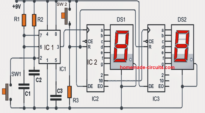
Parts List for the discussed digital counter circuit
- IC1: 555
- IC2 = IC3 = 4026B
- DS1 DS2 = = 7 segment display
- C1 = C2 = C3: 0.047uF
- R1: 10K 1 / 4W
- R2: 1M 1 / 4W
- R3: 33K 1 / 4W
- Switches SW1 = SW2 = normally open push to ON switches
0 to 99 Counter using IC 4518, and 4511
The circuit using ICs 4518, 4511, and a common cathode display is a binary counter with a decimal output. It can count from 0 to 99 and display the count on a 7-segment display.
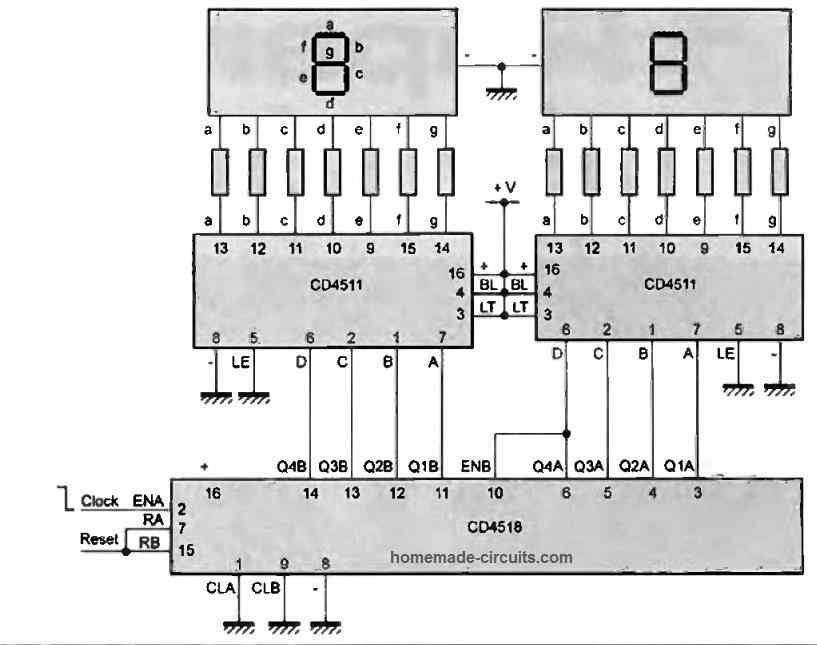
The IC 4518 is a dual BCD (binary-coded decimal) up-counter, which means it can count up in decimal from 0 to 99. The two counters are cascaded so that the second counter counts up by 1 every time the first counter reaches its maximum count of 9.
The output of each counter is connected to a BCD to 7-segment decoder IC 4511, which converts the BCD code to the corresponding 7-segment display code. The outputs of the decoder are connected to the corresponding segments of the display.
A common cathode display has a single cathode connection for all the segments. The cathode is connected to ground, and the anodes of each segment are connected through a current-limiting resistor to the outputs of the decoder.
When the circuit is powered on, the counters are reset to 0, and the display shows "00". Every time the count reaches 99, it resets back to 0, and the display starts counting again from 00.



Questions & Answers
HI Swag, I read lots of comments so I don’t ask something answered previously. BTW I love this site.
Is it possible to use the peoples counting circuit or another without a clock, and replace the trigger with a reed switch so it can count reps of weights lifted. I could just put a magnet on the bar and have reed switch close.
You advice would be very much appreciated.
Thanks
Russell
Thanks Russell,
Yes, why not, that’s perfectly possible, you can replace the counter circuit with a reed switch and enable the counter to measure the number of magnet switching repetitions…
I’m pretty amateur in electronics, in this circuit, where do I turn on the ground? I’m trying to make a timer from 0 to 99, I’m going to see if I can do that one. I’m from Rio de Janeiro, Brazil, thank you.
The bottom most line associated with SW1, C1, C2, C3 etc is the ground line.
Obrigado.
Swagatam,
hello, i am in process of wiring the above counter circuit and may need specifics on the CD4026B pinouts. pin 1 = clock input, the a thru g segment outputs are 10, 12, 13, 9, 11, 6, 7 respectively. your diagram shows pin 10 as an output on IC2 feeding pin1 on IC3 (a conflict). Shouldn’t this be pin 5 on IC2 (carry out) feeding the clock input pin1 on IC3? Also is DE (display enable) an input using pin 3 on both counters? And no connection shown for Vss and Vdd. link for referencing the data sheet:
https://www.ti.com/lit/ds/symlink/cd4026b.pdf?ts=1669708216111
thanks Henry Marotte
Hello Henry,
It will be difficult for me to answer your questions because I have not studied the 4026 IC properly. The above circuit was contributed by an external source so I can’t suggest whether it is correct or not.
You can try the circuit as shown in the diagram, if it works then no problem otherwise you can try the corrections as per your thinking and the datasheets.
The +VDD and -Vss should be connected across pin#16 and pin#8 respectively
Swagatam, Hello. Does this circuit increment on its own? i want to use a circuit like this for incrementing 0-99 from a simple dry closure, in this case a lap counter for racing, and do not want to have it increment on its own. Just wondering, thanks.
Henry Marotte
Hello Henry, this circuit will not increment on its own. The count will increment once each time the switch SW1 is pressed
hello swag I have a temperature Measurement device which displays temperature using senor probe with lm35 in probe for sensing…..problem is anyone can make probe using lm35 and measures it i want a config or circuit that makes it solely measure using my probe and not other who make it…in short basically i want to make my device smart by using only my lm35 probe with extra circuit and should not display anything when used by other made probes please help….Thanks and regads
Hello Dhruv, you can change the format of the +/- out pinouts of the probe so that they cannot be recognized and while connecting to another probe the pinouts will not match and the LM35 will not function. Adding an external circuit will change the behavior and characteristics of the LM35 and then the probe cannot be used in its standard form.
Thanks swagatam for your reply…but the problem is there are hardly three pins and one can just do several combinations to find out the +/- pin in a bid to copy and make…in meanwhile can you suggest me some Digital temperature ICs….where we can enable a security code??…Thanks and Regards
Thank you Dhruv! Yes, the 3 pins can be swapped through different combinations for getting the right combination. In that case you can put a 4rth or 5th dummy pin to create confusions. I don’t think there are any temperature sensor ICs which can be programmed with a security code. Unfortunately I do not have any information about such ICs.
yess this is a considerable option for me… thank you so much swagatam meanwhile there’s a digital IC ds18b20 where there’s a unique 64-bit code if by any chance we can write that code of ours that would be great to validate on software side
You are most welcome Dhruv! Actually my expertise in electronics is limited to designing small circuits only. My knowledge of coding for programming is absolutely nil, so writing codes is something too complex for me.
hello Swag says I need a counter with 2 numbers, but I want this counter to count as much as the number I gave, so if it counts according to the data I have written, can we do it and how do I need it? thank you so much ……sorry for my englisch.
Hello Burhan, you can try the following designs:
https://www.homemade-circuits.com/5-digit-frequency-counter-circuit/
How to Cascade IC 4033 in Multiple Digit Counter Display
Dear Swagatam ?… how to change the circuit so that it can even go back 99-0? thanks for every suggestion. Claudio
Dear Claudio, this circuit cannot be used in the reverse order, however after some searching I could find the following design, perhaps this might do the job
Thanks Swagatam … help me to understand … a square train of impulses generates the increment and the other, inverted, generates the decrease? Thank you so much. Claudio ?
Hi Claudio, yes that may be correct, I got this schematic from a Youtube video but the video was incomplete so I could not confirm the working of the design
Dear Swagatam,
Thank you for sharing all your great circuits and please continue the great work.
To this circuit a have a couple of questions which I hope you will explain to me.
1: Would you be so kind to show the pin numbers of IC2 and IC3. I mean what is the pin of CE, the pin of DE and so on.
2: Shouldn’t the IC2 & IC3 be connected to VCC and VSS?
3: How do I set the IC1 (555) to automatic / manual clock (pulse)
Best regards,
Henrik
Thank you Henrik, the circuit was taken from some other site, I did not check the details.
I have updated the 4026 pin data at the bottom of the article, please match it accordingly.
CE = clock enable
yes IC2, IC3 Vcc/Vss are not shown and these must be connected with the supply rails.
SW1 can be used for manual clocking, if not pushed the IC will continue with its automatic pulsing
hai, the above circuit will work as 0-99 seconds display. How to change this circuit as 0-99 minutes circuit with the total two 7 segment display? Like, after every minute only the number should get increament in display. Pls help..
you can use the following circuit
https://www.homemade-circuits.com/2011/12/simple-frequency-counter-circuit.html
i want the circuit which will only increment when i push the button ……………………………and reset the reading when i push the button ….?????.
use any online 555 calculator software for determining the resistor values for it…the duty cycle results will give the ON/OFF periods..
I tried to find a 555 astable circuit with 60 seconds off and 1 second ON. but not able to find. Could u pls provide me a circuit for that?? Thnkx…
Hi, just replace IC1 with a 1 minute 555 astable circuit