This fan speed controller works by sensing the temperature of the engine and is accordingly used for the triggering. As the temperature increases so does the speed of the fan motor and vice versa.
Circuit Operation
Operation of the proposed temperature controlled fan may be understood as follows:
The speed of the DC motor alters as the temperature increases which is converted into a proportionately rising voltage and applied between its terminals.
To measure temperature thermistor (R1) to be placed as close as possible to where you want him to sense temperature is used.
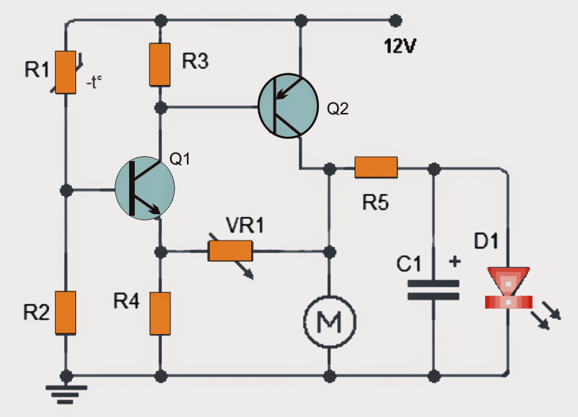
In the diagram, one can see that the thermistor (R1) and the resistor (R2) are employed to form a voltage divider network. It is recommended that the value of R2 is around approximately one tenth of the value of R1.
As the temperature thermistor value decreases it causes the transistor Q1 to saturate harder proportionately.
Since the collector of Q1 is connected to the base of Q2, the voltage at the base of Q2 also responds to the above and decreases
The voltage decreases at the base of Q2 which becomes saturated harder, causing the collector-emitter voltage (VCE) to lower thus intensifying the voltage on the collector terminal of the motor.
The maximum speed of the motor will be slightly less than its rated specification.
To add to this, it may not be crucially necessary for precise circuit operation, to know the temperature in order to control engine speed an LED may be used as given in the diagram. This LED will proportionately get brighter as the engine speed increases.
Circuit Diagram
Parts List
R1: 15K thermistor
R2: 1.5K
R3: 1K
R4: 47
R5: 680
VR1: preset 22K
C1: 100uF/25V
Q1: 2N2712 (NPN) or equivalent
Q2: BD140 (PNP) or equivalent
D1 LED
M: Motor DC brushed or brushless
Note: The DC motor can be different from a computer motor. Make sure that the current rating of the motor does not exceed the rating of the transistor Q2. (maximum current 1.5 amps). It is recommended not to exceed 1 amp and use sink.

Questions & Answers
Hi, my friend!
I found solution.
Almost any MOSFET transistor can be used, but so that the current matches the consumer. I tested the cooler option 24v 350mA. With a tuning resistor, you can set the cooler to turn on even with a slight change in temperature, even with breathing.
It is possible that after testing this scheme yourself, you will include it in your collection, since this option is very difficult to find on the net.
Please, see circuit here
Thank you so much friend,
The circuit looks great and super easy to build. I am glad to have this simple circuit posted in this article. I am sure other viewers will find this circuit very very useful.
Hi, friends!
R9 – 50k resistor for smooth regulation!
OK, go it, thanks for the update friend!
Can you advise a circuit to control 24v DC Fan depending on temperature?
Thank you.
I don’t have a 24V design right now, I may have to design it…
Can you explain to me the calculation of the transistor operation? And if I want the motor to rotate at 28 degrees, how should I calculate it? Sorry to you but I’m a newbie.
It is already explained in the article….28 degrees operation is not possible using the above circuit
I have a 10k thermistor can i use this.
yes will do!
Awesome website! So many projects and circuits to try, THANK YOU!!
Question: Is this circuit working off PWM or would you have to implement a 555 chip?
2nd: Can I make this work with larger mosfets, the range of 30-35 amps, if so a recommendation?
3rd: I have a thermister that is @ 2795 ohms @ 77*F looking to run up to 104*F and that temp I’m @ 1465 ohms. I would like to start out at around 30-40% fan speed then full on at the 104*F, Is this doable with this circuit?
Thanks in advance!!
Thanks, I am glad you liked my site !
this circuit does not employ a PWM, rather on linear voltage variations in response to the thermister resistance changes.
A IC 555 may not be required if heat dissipation is not a problem.
The mentioned thermistor will work, just make sure to dimesnion R2 according to the thermister specs, in your case you can try a 1K preset for R2 and set it accordingly, for achieving the correct triggering threshold
Dear Swagatam,
In the parts list, VR1 is shown as preset to 22K. Why is this a variable resistor? Also, in order to be able to adjust the initial speed of the fan, would that be done by replacing R4 with a variable resistor and if so, would an appropriate value be 100K with the initial setting to the mid point?
I want to thank you for providing this wonderful resource to the world. I have seen comments from many countries and I want you to know that your knowledge and willingness to share it is greatly appreciated.
Pat
Tigard, Oregon, USA
Thank you Pat,
I assume VR1 is actually for setting the initial speed for the fan. A higher resistance across VR1 will allow higher initial speeds and vice versa.
This circuit is not designed by me, it looks good and should work as proposed.
thank you for your kind explanation sir,
As the temperature thermistor value decreases it causes the transistor Q1 to saturate harder proportionately.
Since the collector of Q1 is connected to the base of Q2, the voltage at the base of Q2 also responds to the above and decreases
dear sir , i cannot understand the following line please explain simple words(The voltage decreases at the base of Q2 which becomes saturated harder, causing the collector-emitter voltage (VCE) to lower thus intensifying the voltage on the collector terminal of the motor.)
thank you sir
bala
Dear bala,
as R1 decreases T1 conducts more due to more positive voltage through R1, which in turn provides more negative voltage to T2 base and enables it also to conduct more until both the transistor are fully ON