When searching for an object, our initial instinct is to rely on our vision. However, the Tracking Transmitter circuit featured in this article offers an alternative by utilizing sound. The Tracking Transmitter emits a sequence of brief, modulated tones that can be detected by most FM receivers as a distinct beep. By: Ronit Roy
Basically the tracking transmitter is supposed to be installed on a given object. Next, by utilizing an FM radio receiver, whether it's mobile or portable, one can explore regions where the object may be found.
By detecting the transmitted signal from the object, one can determine the direction of the signal by altering the position of the radio receiver.
With this method, you can roughly locate the object. By continuously scanning the area, you can eventually identify the precise location of the object.
How the Circuit Works
The Tracking Transmitter is a very basic circuit composed of four independent sub-assemblies: a free-running multivibrator, a transmit switch, an audio -tone generator, and an FM transmitter.
The multivibrator is employed to regulate the transmit switch, which switches both the audio generator and the transmitter on and off at a predetermined rate.
This ensures that power usage is at the minimum level. The audio generator's output goes into the FM transmitter, which emits a repeated beeping in the 88- to 108-MHz band that may be captured and heard by a standard FM receiver.
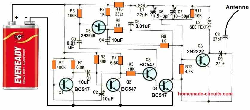
The figure above depicts the Tracking Transmitter's schematic diagram. The multivibrator is composed of several components, including Q1, Q2, C1, C2, and R1 through R4. Specifically, R2 and R3 have been selected to generate a 300-millisecond pulse width with a 1500-millisecond pulse separation.
The collector of Q2 obtains the output of the multivibrator, which is then transmitted through R5 to Q3's base. Q3's output, taken from its emitter, is employed to activate Q4. The two transistors, Q3 and Q4, constitute the transmit switch.
As soon as the multi-vibrator produces a positive swing, Q3 is triggered and turns on, subsequently activating Q4. With Q4 switched on, the emitter of Q6 is pulled to the ground, causing it to conduct.
Whenever Q6 conducts, it transfers any signal that is applied to its base to the antenna.
The antenna is linked to the intersection created by C8 and C9. The audio-tone generator, comprising components Q5, R6, R7, R8, and C3, produces an output that is connected to the base of Q6 via C4 and R8.
When the multivibrator output undergoes a negative alternation, Q3 and Q4 switch off, causing the transmitter to turn off as well.
The circuit's transmitter section consists of components Q6, R10, R11, R12, L1, L2, and C5 through C9, which function within a frequency range spanning from below 88 MHz to above 108 MHz.
Capacitor C7 provides coarse tuning for the transmitter, while C6, an optional component, offers fine tuning capabilities.
For the antenna, a 6- to 12-inch length of stranded insulated wire connected to the appropriate circuit point suffices.
The Tracking Transmitter is meant to run on a 9-volt battery, but it can also operate with voltage inputs ranging from 5 to 18 volts. The higher the voltage, the more potent the output signals.
How to Construct
The Tracking Transmitter's layout is relatively compact, with a circuit board that measures 2 and 1/2 inches in length and 1 and 3/16 inches in width, as shown below.
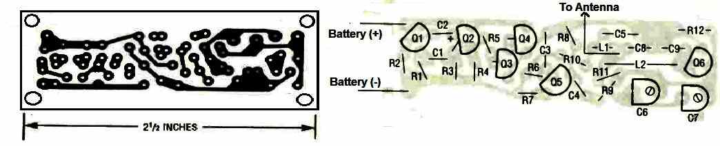
When constructing the Tracking Transmitter, it's crucial to minimize lead length to prevent unwanted capacitances and avoid looping component leads to limit undesired inductances.
All components, except for the battery supply, are situated on the printed circuit board. Refer to layout design to install all board-mounted components carefully, taking care to verify all transistor pinouts before mounting.
It's important to note that all axial-lead components, including R1 through R12 and L1, should be mounted vertically.
The electrolytic capacitors should be miniature radial-lead units; if axial-lead electrolytics are used, they must also be miniature and vertically mounted.
How to make the L2 Coil
Inductor L2, is a hand-wound, air-core coil comprising seven turns of #22 solid magnet wire.
To create the coil, take care to wrap precisely 7 turns of the specified wire around a 5/32-inch drill bit.
After winding, strip off the insulation from both ends of the coil, insert the ends into the appropriate holes on the printed circuit board, and solder it firmly into place, ensuring a robust electrical connection.
Once the coil is formed and installed on the circuit board, avoid moving it to prevent accidental spreading of the windings, which could alter the coil's inductance and cause difficulty in tuning within the FM range.
Finishing the Assembly
After mounting all the on-board components, attach the antenna, which should consist of a 12-inch length of #22 stranded insulated hook-up wire.
Next, connect a 9-volt battery snap to the circuit. To include an on/off switch, connect the switch in series with one of the battery leads.
Although the Tracking Transmitter can function without a chassis box, you may opt to house it in a small plastic or metal box, particularly if you are incorporating an on/off switch.
A metal box is preferable because it enhances the transmitted frequency's stability and ease of adjustment.
Testing
Inspect your work to ensure proper assembly and check for any short circuits. Verify that each transistor is correctly oriented and in the correct location.
Verify that each resistor is in the appropriate location and has the correct value. Connect a 9-volt battery to the circuit.
Using an oscilloscope, examine the signal at the collector of Q2. You should observe a pulse train with a peak-to-peak amplitude of around 8 volts.
The positive-going pulses should be approximately 300 milliseconds wide and should be separated by approximately 1500-millisecond intervals.
If you do not have an oscilloscope, attach the ground lead of a non-digital voltmeter to the battery's negative terminal.
Set the voltmeter to 10 volts or higher. Connect the positive lead of the voltmeter to the collector of Q2. The meter reading should repeatedly fluctuate from approximately 1 to around 9 volts.
Next, turn on an FM receiver and tune it to an unoccupied frequency between 88 and 108 MHz. Use a non-conductive alignment tool to adjust C7 and C6 until you hear the transmitter on the receiver.
You may need to compress or expand L2 to ensure that the Tracking Transmitter can be tuned from the low end to the high end of the band.



Questions & Answers
Hello, Q5 is drawn as an N-Ch FET however the part 2N2646 crosses to a UJT or uni-junction transistor. Can you clarify the basing and part info?
Thank you for all your efforts,
Hi, Q5 is not an FET, it is an UJT.