In this post I have explained how a landline telephone can be rigged up wirelessly with a small transmitter circuit, enabling easy tapping of the telephone, by transmitting the conversations to a distant FM radio appropriately set up for the listening.
Circuit Description
The circuit diagram for the Telephone Transmitter can be witnessed in the figure below. That design is supposed to be connected in series with one of the telephone lines ow telephone input wires.
Power to the circuit is extracted through a full-wave bridge rectified which is taken from the phone line itself via the diodes D1----D4. Transistor Q1, capacitors C1 and C8, along with the inductor L3 work like an FM oscillator operating with a frequency of approximately 93 MHz.
Adjustable trimmer capacitor C8 enables the oscillator frequency to be tweaked through 90 MHz and 95 MHz. To be able to stretch the tuning range up to the 98 and 105 MHz range, C1 could be substituted with a 10 pF capacitor.
The voice frequency from the phone line is connected by means of resistor R3 and capacitor C2 on the base of transistor Q1, which subsequently modulates the audio with the oscillator frequency. Next, transistor Q3, inductor L1, and capacitor C6 are configured to work like a power amplifier.
The signal extracted from the inductor L3 tapping is supplied to the transistor Q2 base which then enables the transmission of the modulated FM signal via the collector pin of the Q2 transistor. Inductor L2 is configured like a radio-frequency shunt which decouples the power supply DC from the amplified audio signal.
How to Build
The telephone transmitter circuit is very straightforward and could be built over a veroboard, although the compact PCB design shown below looks more preferable and is recommended.
While assembling the parts on the PCB, you may refer to the component overlay diagram as illustrated in the following figure.
Get started by fitting and soldering the resistors and diode. You may find the PCB layout very compact and therefore you may have to assemble most of the horizontal parts in vertical mode. Next, it is time to install and solder the inductors.
Constructing and Fitting the Inductors
Inductors L1 and L2 can be wound by using 6 and 8 turns of super enameled copper wire, respectively.
If you decide to wind the coils at home, you may use around 22 SWG super enameled copper wire and a 1/8 inch drill bit as the measure for the winding former.
The enamel coating at the coil wire ends which need to be soldered, must be thoroughly scraped, and cleaned until they are shiny and without any layer of the enamel, so that they can be perfectly soldered on the PCB.
Coil L3 can be built using 6 turns of tinned copper wire over a 1/8 inch diameter former. After winding, make sure to pull and stretch the coil turns about 1 mm apart from each other and also ensure none of the turns are touching with each other.
Next, you must extract a tapping by scratching off the enamel coating from the top of the first turn of L3, and then solder a wire on it, which can be connected on the specified PCB point.
Once the coil assembly is over, start soldering the fixed capacitors along with the variable trimmer. After this you can go for the transistors and solder on their respective slots.
This concludes the assembly of the phone transmitter circuit.
Before you hook up the transmitter to the phone lines make sure to examine the PCB and the part assembly for any possible errors, and rectify them appropriately if you find any.
The transmitting range of the circuit is over 100 feet. However, it is easily possible to extend this range significantly by soldering a flexible wire antenna (approximately 150 cm in length) to the collector of Q2.
How to Tune and Set up the Transmitter
Connect the Transmitter inputs in series with one of the telephone lines through any suitable method you are comfortable with. Switch on a FM radio positioned somewhere near, and tune it to a relatively silent spot on the FM band, which can be anywhere in the region of 90 and 95 MHz.
Now, pick up the telephone handset; this must immediately allow you to hear the dial tone loud and clear on the selected FM radio band. If that doesn't happen, you may try tweaking the trimmer capacitor C8 until the dial tone is heard distinctly on the radio.
In the process, first fine-tune C8 to get the most suitable reception on the FM radio, next tweak the radio knob for improving the outcome even further. In case you find it difficult to get a null spot on the specified band, remember that it is possible to expand the tuning range up to the 98 to 105 MHz mark, simply using a 10 pF capacitor in place of the C1 capacitor.
More information regarding the telephone transmitter was found from the website electronics-diy.com/index.php, which can be witnessed in the following image.


Questions & Answers
Dear Sir engineer Swagatam,
Hello, I hope you are doing well and staying healthy. I have sent the circuit diagram of a condenser microphone amplifier to your email address. I have assembled it and replaced the carbon microphone of a vintage telephone set.
I would greatly appreciate it if you could design a similar circuit as a replacement for the carbon speaker of the aforementioned telephone. I believe that these circuits would not only be appreciated by your website visitors, but would also be very useful for my grandmother, whose hearing is weak.
Thank you in advance for your kindness.
Sincerely yours
Ersa
Thank you so much Ersa,
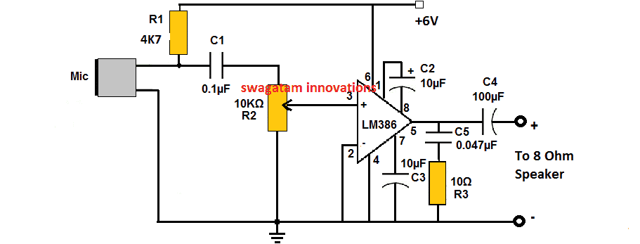
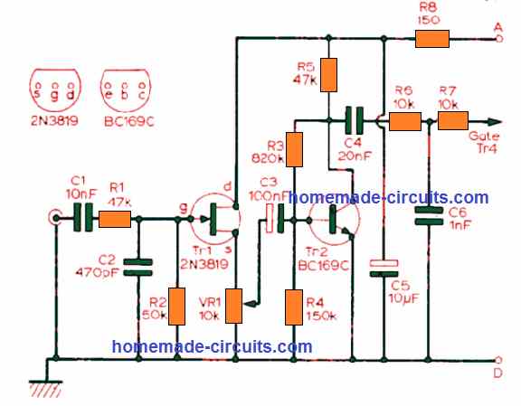
I saw your diagram, You did it correctly, and in your circuit the R3 (10k) is the main element which allows the electret MIC to work soundly in the circuit and this resistor can be used also for adjusting the sensitivity of the MIC. here’s a full circuit of a nice and powerful hearing aid anyone can build and test:
Hello dear Sir Swagatam
Another question came to my mind just now
For my purpose, should I ignore/eliminate the microphone and connect the input of your circuit to the carbon speaker of the telephone socket?
Thank you so very much dear Swagatam
Best wishes
Ersa
Hi Ersa,
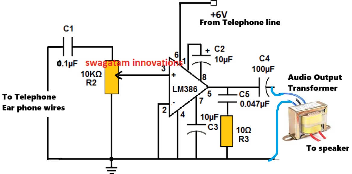
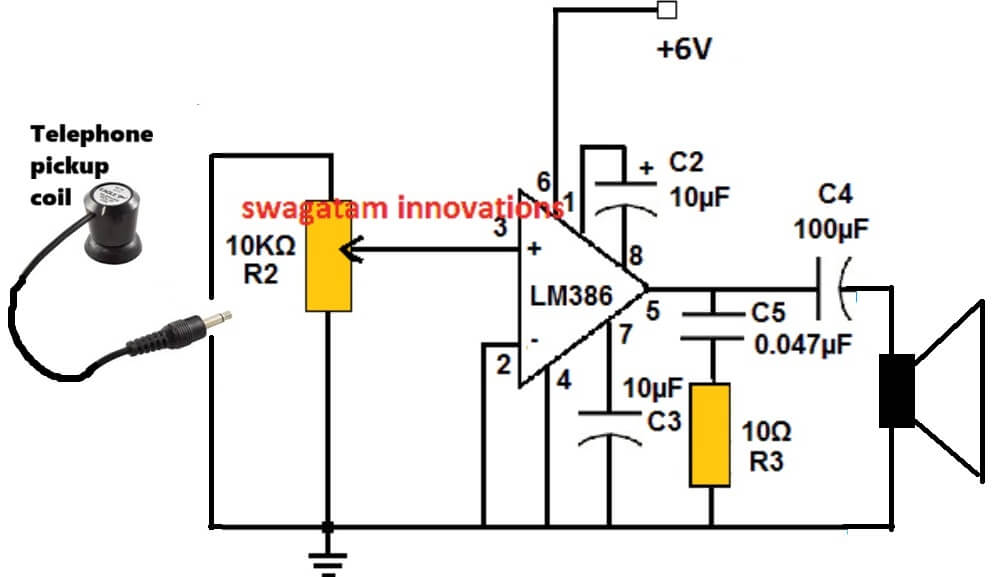
Yes microphone can be removed and the capacitor wires directly connected with the telephone earphone connections. Here are two circuit options you can try:
The above design does not depend on external power and uses the telephone DC for operating, but uses an output audio transformer for isolation…
The above 2nd diagram uses an external DC for operating and uses a pickup coil placed near the telephone instrument or the wires to sense the telephone audio…
Dear Sir engineer Swgatam
Hello, you are truly wonderful, sir. Every time you respond to me, you fill me with excitement due to your immense kindness. I find myself wondering if a man could truly be so good.
God bless you.
Based on your instructions, I can assemble the following circuit diagram that does not require an external power supply, instead of using the built-in carbon earphone:

If this is correct, please provide the following information:
1. Where should I connect pin number 6 of LM386 in the above circuit?
2. Am I correct in assuming that I no longer need the TIP41A circuit?
Thank you in advance for your kind response.
Warmest regards
Ersa
.
Thank you Dear Ersa,
Sure, You can try that circuit with an audio output transformer.
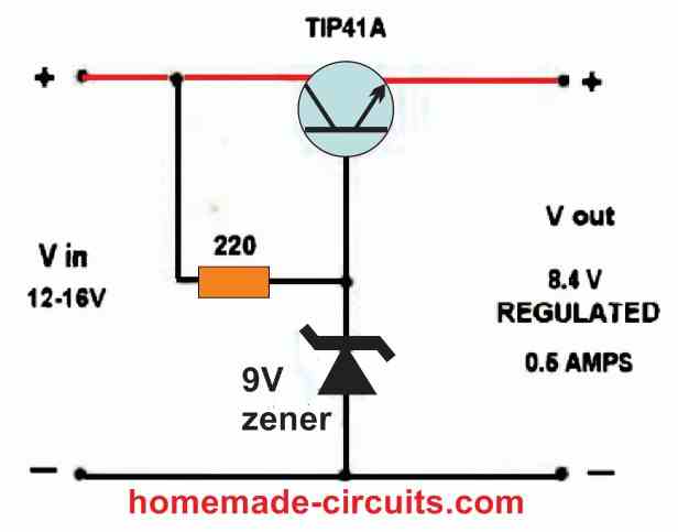
The TIP41 regulator will be required for this circuit, after rectifying the phone DC through a 1N4007 bridge rectifier stage. This regulator circuit will ensure that the amplifier circuit always gets the required 5V or 6V from the phone line regardless of the phone line supply levels.
So the TIP41 emitter output from this regulator will go the pin#6 of the LM386, and ground line will connect with the amplifier ground line.
You can also try a BD139 for the transistor instead of TIP41…
Dear Sir engineer Swagatam
Hello, this is the third time I am sending my response to you. Neither of the previous two times did I receive the message “your comment is being…”. Perhaps you did not receive those.
Dear Sir engineer Swagatam
Hello, thank you so much for your thorough and thoughtful response. Your great favor and kindness are always apparent to me and I truly appreciate it.
** I will also replace the 9V zener diode in the diagram with a 6V zener diode to achieve a 5v output for the LM386.
Take care of yourself, as there is only one of you in the world.
God bless you.
Warmest regards.
Ersa
Dear Ersa,
I have replied to all your comments so far, with the required schematics, please check this article below, and you will find it all here:
Let me know if you are getting the email notifications or not?
https://www.homemade-circuits.com/telephone-transmitter-circuit/
Dear Sir Swagatam
Hello, I have received all your responses and Emails.
Thank you very much for your efforts and kindness
With warmest regards
Sincerely
Ersa
Thanks Ersa! That’s great!
All the best to you.
Cheers!
Dear Sir engineer Swagatam
Hello, You could never imagine how pleased I am with the hearing aid circuit that you designed for my grandmother, and I am sure she will pray for your health every day.
Just a question, sir: How does it use energy from the telephone line if I do not use an additional 6v power supply?
Please excuse me Sir but Is it possible, or would it be practical to make some changes in the circuit so that it works with no need to additional power supply? if your response is no, what would be the minimum voltage of the power supply.
Thank you again for your invaluable kindness.
He who never forgets your huge kindness
Sincerely
Ersa
Thank you Dear Ersa,

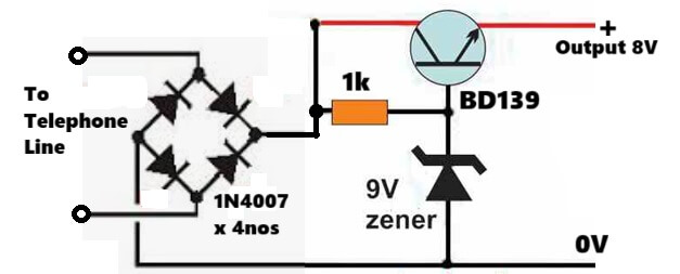
Yes you an use the power from the telephone line to operate the circuit, but in that case the output speaker will need to be isolated through an audio output transformer for guaranteed safety, because the telephone also carries high voltage which may not be safe for the user.
So you can use the following circuit for stepping down the telephone line voltage to the required 5V level for the LM386 amplifier circuit as shown below, the input voltage can be upto 80V, but make sure to use a bridge rectifier to convert the telephone line voltage to a positive DC for the following circuit….the zener value must be 1V higher than the required output voltage for the amplifier….
Great circuit! I have had tried similar circuit some 3 decades ago and transmitted within 3 km range. I would rather like to pick up my naughty granddaughter’s mobile phone which is harassing me these days. Any idea, please let me know on my email.
Thank you.
Muni Raj
Thank you…That sounds interesting, however unfortunately this circuit cannot be fixed on mobile phones, since it is too big to be inserted into a mobile, nevertheless an SMD version of the same can perhaps be tried which possibly might just fit in some corner inside a cellphone.