The following posts explains how to build a simple to build FM stereo transmitter circuit using IC BA1404.
About the IC BA1404
An exceptional stereo audio FM wireless transmitter circuit is presented below.
The circuit relies upon the IC BA1404 from ROHM Semiconductors.
BA1404 is a monolithic FM stereo modulator which includes integrated stereo modulator, FM modulator, RF amplifier circuitry.
The FM modulator could be controlled from 76 to 108MHz and power source for the circuit could be nearly anything between one.25 to three volts.
Circuit Operation
In the circuit R7, C16, C14 and R6, C15, C13 makes the pre-emphasis system for the right and left stations respectively.
This is achieved for complementing the frequency response of the FM transmitter with the FM receiver.
Inductor L1 and capacitor C5 is employed to fix the oscillator frequency. Group C9,C10, R4,R5 enhances the station splitting up.
38kHz crystal X1 is linked between pins 5 and 6 of the IC. Composite stereo reception is formed by the stereo modulator circuit employing the 38kHz quartz regulated frequency.
Construct the circuit on a high quality PCB.
Operating the circuit from a battery pack minimizes disturbances.
Work with an 80 cm copper cable as antenna.
For L1 try to make three turns of 0.5mm dia enamelled copper wire on a 5mm dia ferrite core.
Stereo FM Transmitter Circuit Diagram
An improved version of the above design is explained in the following post.
The FM stereo transmitter circuit described below can be used for broadcasting a much clearer stereo FM music to all nearby FM radios.
FM basics
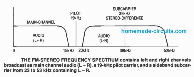
Most of the basic wireless FM transmitters tend to be monophonic only. A stereo broadcast signal features a pair of channels: left and right. The sound frequency cover a bandwidth of 50 to 15,000 Hertz, along with the higher frequencies provided a treble boost or pre-emphasis for noise-reduction.
Each channels are incorporated collectively and broadcast as primary channel audio (L+R) to ensure that monophonic FM receivers will manage to reproduce the entire input music content for the audience to take pleasure from.
Together with the main channel music, a stereo signal includes a 19 -kHz pilot carrier at 10% amplitude of the primary channel, and also a sideband subcarrier from 23 kHz to 53 kHz made up of the difference between the right and left audio signals (L - R).
The stereo receiver makes use of the 19 kHz signal to duplicate a phase locked 38 kHz signal (kept in check at the transmitter) to decode the sideband carriers back into the right and left channels. The following figure displays the frequency spectrum of an FM stereo signal.
The receiver additionally offers a treble cut (known as de-emphasis), that makes up for the pre-emphasis that has been included at the transmitter.
How it works
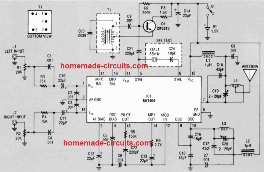
The main part of this circuit design is the IC1, a BA1404 FM stereo transmitter as shown in the figure above. The left - channel input signal is tweaked to correct level by RI.
Treble boost (pre-emphasis) is supplied by the parallel blend of Cl and R3.
This matches the acoustic specs to the standard 75 microsecond as per the rules by the FCC. Sound is paired by C10 to the left-channel input of IC1 on pin 1. Bad RF disturbances are bypassed to ground via C2 to protect against undesirable feedback.
The right channel input stage to pin 18 of ICI is actually the same as the left channel. Power supply decoupling executed by C14, and any prior amplification for the sound input is decoupled by C12 on pin 2 of the chip.
A 38 -kHz signal is necessary to multiplex the incoming sound and develop the preliminary carrier signal.
The inner circuit stages of IC1 facilitates the application of a 38 kHz SX-cut crystal, as proven by the dotted line within the schematic of Figure above.
However, the 38 kHz crystals can be tough to get in the market, plus they may cost a lot if you happen to get one.
A much more easily accessible crystal, may be available that operates at 38.400 kHz.
This works in the majority of conditions: studies conducted in the course of the development of this particular design confirmed that a few FM stereo receivers might not "shake hands" reliably to the pilot carrier created from 38.400 kHz crystal.
The remedy was to work with an extremely secure alternative Hartley oscillator built using cheap, easily accessible components in place of either crystal oscillator.
The 38 kHz sine wave is produced by Q1 and the adjacent parts (the Hartley oscillator). High gain transistor Q1 features a gain of over 300: lower gain devices may well not perform because of the reduced supply voltage (1.5 volts DC) which is supplied by a single AA cell.
The variable inductor employed for T1 is a 1st intermediate frequency (IF) transformer commonly seen in portable transistor radios, and it is intended for 455 kHz processing.
The coil in T1 is packed with ample capacitance by C23 to carry its working frequency down to approximately 38 kHz. It is possible to fine-tune Ti's core to place the oscillator precisely on frequency.
Despite the fact that the oscillator may possibly drift a lot more compared to a quartz crystal, it's certainly not an issue simply because receivers make use of phase locked loops which could track the trivial floating away.
Take note that the circuit is not going to oscillate if transformer Ti's wiring is flipped or reversed. A base view of Ti is shown in Fig to assist you with the connections.
The multiplexed audio tracks comes out of pin 14 of IC1 and is blended with the pilot carrier on pin 13 with the aid of the circuitry of R5, R6, C22, and C13.
The resulting audio output is sent to the modulator input at pin 12. To circumvent any kind of RF feedback complications, pin 12 is bypassed through C6. A Colpitts oscillator, working from 88 to 95 MHz, is created at pins 9 and 10 together with the circuitry of C15 to C17, C20, and L3.
The crude frequency realignment is done by adjusting the coil turn gaps of L3, and the fine tweaking done via C20.
RF energy which is developed through the tank circuit is held back from running back into the power supply stages using bypass capacitor C7 and RF choke L2.
The crude frequency realignment is done by adjusting the coil turn gaps of L3, and the fine tweaking done via C20. RF energy which is developed through the tank circuit is held from running back into the power supply stages using bypass capacitor C7 and RF-choke L2.
The modulated transmission at pin 10 of ICI is combined internally to the RF output amplifier comprising C18, C19, and L4 attached to pin 7.
This stage enhances the oscillator audio to commute the antenna, and this inhibits variations in antenna loading via switching the oscillator frequency.
A tap is extracted at a point on L4 on the antenna for having the highest possible power transmission.
The structure of IC1 is hard-wired intended for 1.5 volt operation having an absolute maximum of 3.5 volts.
Initial examining of this circuit revealed that the broadcast range failed to expand substantially when 3 volts was utilized to supply the circuit, and the current consumption increased 3 times .
As a result, the rise in operating voltage is not really advised. The FM transmitter circuit consumes just about 5 mA, therefore just one AA cell might serve for a quite a while.
Construction
Any circuit working with high frequencies demands appropriate grounding and shielding. However. in order to make this assignment as easy as possible, a PCB was not used.
Instead of a PCB, an empty one sided copper clad had been utilized, with the copper on the component side creating a ground plane, and wiring connections done on the opposite side.
The constructor will be able to identify each of the essential components intended for this circuit design.
As demonstrated in main figure, the majority of the components can be seen with one terminal heading straight to ground. For these components you need to drill a hole through the board just for the ungrounded pin.
The other pin could be soldered right to the ground surface on top of the PCB. It is recommended that you drill and solder the parts step by step. Doing this it might be simpler to fix each of the components correctly.
Make sure to maintain all terminals as small as you can.
Additionally, ensure that decoupling capacitors be positioned as near as feasible to the pins of ICI, L3, and L4.
You can construct coil L3 by compactly winding 3 turns of #20 enameled wire upon the shaft of a 3/16 inch drill bit and stretching it out to 1/4 inch immediately after its taken of from the drill bit.
To create coil L4, wind four turns of #20 wire closely as suggested before, and pull the turns out up to 3/8 inch after removing from the drill shaft. Each coils are installed on the board 1/46 inch raised over the board copper surface.
Position the coils at right angles to one another and at minimum 1 inch separated to minimize coupling across the two. The RF chokes (L1 and L2) also needs to be installed at right angles to coils L3 and L4.
Checkout and tune up Take a couple of minutes to examine your hard work. Make certain the copper is taken off all around the slots meant for component terminal through pass.
Prior to switching ON power, do a couple of inspections with the ohmmeter from ICI's pins to ground to verify if any kind of shorts are present where these really should not.
Additionally look for appropriate polarity of the electrolytic capacitors. Attach the battery and determine the current drain; it must be below 5 milliamps.
Connect the antenna to the top of L4, on the very first turn from the end which is linked to pin 7 of IC1.
The 17 inch antenna shown for the prototype will be the size in most cases identified on portable radios; use just the right size for the antenna to prevent disturbances with the radios nearby. Integrate a stereo music signal to the transmitter left at J1 and right at J2.
Adjust your FM radio across the whole band tuning in for the transmitted signal. Adjust C19 and C20 at their center points and fine-tune L3 at around 92 MHz. Now you can employ C20 to align for the specified frequency.
Even though you most likely have a decent broadcasting range, it is possible to optimize the circuit for highest output by tracking the signal power indicator on the FM receiver you may be working with, and stretching or compressing the coil gap between the turns of L4 using a insulated, non-magnetic instrument.
As you near the optimum point, the coils tend to be somewhat interactive, therefore modifying just one may impact the other. Keep doing the procedure until you achieve a highest possible outcome.
Having a stereo signal placed on J1 and J2, tune in to the output from the FM receiver, ideally via headphones, and fine-tune R1 and R2 to the level slightly below where distortion comes about on noisy parts of audio. An signal level slightly below 200 mV is recommended at the input.
The 38 kHz oscillator is ideally tweaked using a frequency counter attached to pin 5 of ICI.
If the equipment is not accessible, you may fine-tune the core of T1 reading the positions where the receiver's stereo indicator light triggers ON and off. Adjust the core midway in between these two positions.
Additional Adjustments
There could be instances when you would like to broadcast a monophonic transmission, say for example a speaker's output to an auditorium sound system.
A toggle switch could be included with the circuit to insert a 0.01 µF capacitor across IC pin 6 ICI and ground to restrict stereo functioning.
If perhaps a long term monophonic functioning is preferred, the 38 kHz oscillator elements and C5 could be removed from the circuit.
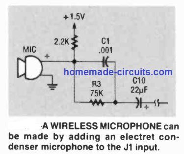
Incorporating an electret MIC to the J1 input with a 2.2K resistor attached to + 1.5 volts will turn this circuit into a wireless microphone for kids-room tracking or for use in lecture rooms. Hook up the components into the circuit in place of R1 as demonstrated below.
Stereo function lets you use two inputs together. You could possibly consider incorporating vocals on one channel and musical instrument on the other for the program from your audio system.
Alternatively, you could also keep track of the phone or an infant on the left channel and tune in to your scanning device on the right channel all at a time as you clean up your vehicle or mow your garden, or when you wear a headphone receiver.


Questions & Answers
Ohhh My 🫢, I never knew I was mentioning transmitter all along so sorry about that, I was referring to the reciever.
this time so If I connect LED to the FM Signal receiver’s audio output terminal instead of a speaker the Led will function as an Indicator.
Thank you sir
For your time
No problem Jeremiah.
Yes, that’s possible. You can connect an LED between the FM receiver’s audio output and the ground line, through any resistor between 1k and 4.7k.
Thank you for this post but sir can I Use any receiver to get the transmission, I thought of DIY FM receiver from this website oar any reliable on that I could use.
And secondly can I add an LED to one of the audio output to serve as an Indicator.
Hi Jeremiah, yes you can use any standard FM radio to receive the signals from the above FM transmitter.
You can add an LED across the speaker of your FM radio, but in the transmitter an LED indication may not be possible..
Thanks for your response.
Do you mean If I Connect the LED, It will not light?
If you connect an LED anywhere in the above transmitter circuit, the LED may light up, but the circuit will stop working.
What can you suggest, I need to get an LED to work as soon as it receives signal.
Would AM transmitter do likewise ?
For detecting a receiving signal, the LED must be placed in the receiver module, not the transmitter.
Would it be possible to replace the RF chokes L1 and L2 with smd ferrite beads? And if yes which frequency should be chosen as they aren’t listed with their inductance.
The frequency and inductance are not known, therefore it seems the coils must be wound exactly as specified in the article
Hi Swagatam.
Thank you for this circuit and all the other incredible content you constantly share with us.
This looks like a fantastic circuit for a project Im am working on to transmit audio from a live dj to cars parked on a field. What is the range of this transmitter circuit. I need to have a bout 200m – 300m range (preferably a bit more if possible). Do you think this circuit would have sufficient transmission power?
Kind regards.
Hi Arthur, I don’t think this circuit will be able to provide 300 meter range, it cannot provide more than 100 meters.
Hello could the modulator circuit be use for the first stage of an fm Home built transmitter with an rf driver an rf power amplifier ..
I am not very sure about it. By the way, a home built transmitter can be easily modulated using a simple transistor stage as explained in the below article:
https://www.homemade-circuits.com/how-to-make-wireless-speaker-system/
Please I want to buy Ic BA1404
i would suggest creating a simple active wifi antenna? can you help me. thanks
how can i simulate this ic as it is not available in proteus?
sorry, in that case I have no idea, better test it practically by assembling the parts, will work without any doubt, if built correctly.
Hello Sir, I Like This Circuit, And I Want To Construct It, But I Have Some Questions To Ask
1. For Instance If I Dont Get 38khz Crystal Oscillator, Can I Generate 38khz From 555 Timer And Feed It To The Circuit? And Can It Work Normal Like For Crystal Oscillator?
2. Can It Be Modified By Adding Press Botton For Scanning Or Selecting The Frequency?
3. Can We Add A Power Indicator Led To It?
4. Can It Be Modified By Adding Sound Indicator Circuit To It?
Solomon, we use crystal to ensure extremely stable frequency which cannot be achieved using ICs like 555, so it might not work.
You may have to refer the datasheet of the IC to learn if any modifications may be possible or not externally.
Music level indicator can be added at the output side of the circuit
i made a BA1404 Stereo FM Transmitter but unable to found stereo FM receiver circuit . Please help me as soon as possible.
you can use your mobile phone’s FM radio…
Can I connect this circuit to the TV output Audio RCA connectors
it's for radio FM range….won't work for TV I guess…
Hello i got this IC but I used a different circuit and its not working out as expected in the first place how do I know the value of the frequency that is being transmitted?
What is the software for doing the simulation BA1404?
though i would suggest creating an LCR meter using arduino..It is an easy build and helps to find transmission frequency.
Hello, It would be difficult for me to troubleshot without practically checking it…
you can check the frequency by capturing the transmission on any standard FM radio and then checking the frequency level on the tuning calibration of the radio.
Checked it…The datasheet didn't help much….
OK, good, thanks for updating the info
that's quite long and sufficient…not sure, there could some other hidden issue somewhere
Currently using a 1.5m long one.
try a longer antenna.
Made this as you instructed….still not getting a clear reception and the audio transmission isn't recognizable. What should I do?
check the datasheet of the IC and see if there's any refinements to be done.
You said 5 turns initially, if I don't get correct transmission, should I increase or decrease the number of turns?
ok……
you will have to experiment with the turns because the original IC datasheet has not informed about the exact number of turns for the coil
Wait then i'm sending the link to ground fill pcb pdf and the silkscreen too….
This is the link to the shared folder on google drive:
https://drive.google.com/drive/folders/0B-5jjw-tjYplaGJuVjN5cGUxOWc?usp=sharing
yes that looks OK to me.
I have neither a ferrite core nor a variable inductor. Please post a way to use a static inductor with a 2-18pf variable capacitor.
yes it must be ground filled type or "copper pour" type PCB to enahnce stability.
sorry I cannot check your PCB if it's posted in some other electronic website.
you can post in some free image hosting site, and send the link here
to prevent noise use PCB with grounded tracks
0.5mm is not critical you can use any other gauge thicker than that….
use 5 turns initially
Please tell me how make this inductor for 22SWG as 0.5mm copper wire isn't available in my city. SWG22 is 0.711mm wide. I have salvaged a 5mm ferrite core. How many turns should I make to use it as an inductor in this circuit?
Wait. I just found a 5mm ferrite core. But since I don't have 0.5mm copper wire. Would you please tell me the improvised version of this coil for SWG22 wire. I can make air core coils according to given values but I don't know how ferrite cores change the inductance value so please tell me how to make a coil with 5mm ferrite core using SWG22..Hope this will eliminate the static caused by my circuit.
ok…made this circuit…but getting too much static. What do you think is the culprit?
…ferrite cored inductor is a must for the explained design
Can this circuit transmit up to 2km? I also want to design mobile Phone call jammer can u pls upload the circuit or show me the link to mobile call jammer circuit. Thanks
is crystal resonator necessary??