• Skip to main content
  • Skip to primary sidebar

Homemade Circuit Projects

Need circuit help? Post them in the comments! I've answered over 50,000!

Blog | Categories | About | Hire Me | Contact | Calculators-online
You are here: Home / Pets and Pests / Solar Insect Killer Circuit for Protecting Crops in Farms


Solar Insect Killer Circuit for Protecting Crops in Farms

Last Updated on January 2, 2024 by Swagatam 4 Comments

The insect killer circuit presented here is designed to attract insects during night, and electrocute them through a high voltage mesh trap. The unit can be installed in farms for protecting crops from potentially harmful insects. The unit being solar powered does not depend on human intervention and works independently.

Table of Contents
  • Insect Trap Set Up
    • High Voltage Generator
    • Making the Electrocution Mesh

In one of our previous posts we came across a simple mosquito killer circuit which Incorporated a high voltage electrocuting device for killing the mosquitoes, here too we apply the same principle for terminating the potential insects using a high voltage mesh trap.

Insect Trap Set Up

The following image shows the basic set up that needs to be fabricated and installed within a farm for implementing the insect control actions.
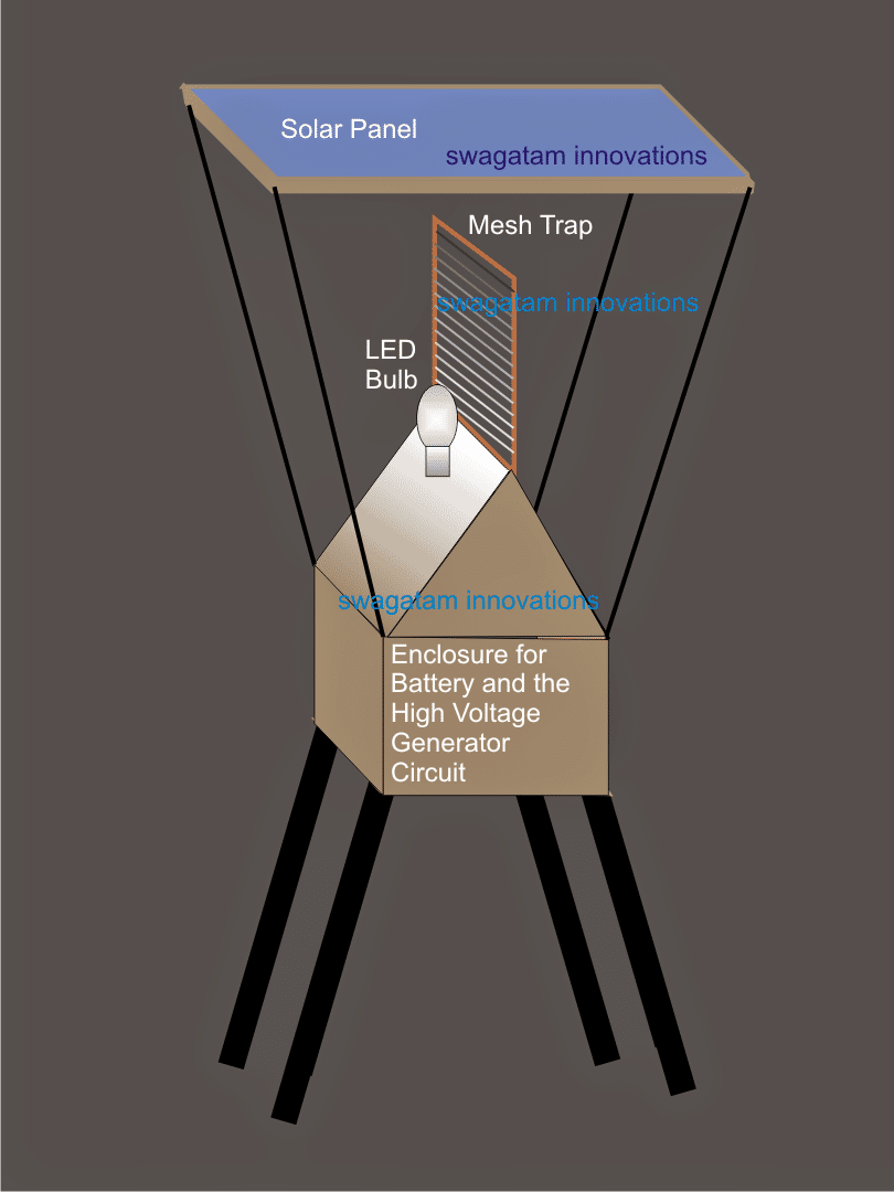
The shown set up indicates a solar panel placed at the top of the structure, the high voltage collector mesh can be seen clamped vertically just below the solar panel, while a LED can be witnessed positioned beside the mesh trap.

The battery and the circuit are enclosed inside a wooden "house" like structure which becomes the base for all the above described fabrications.

The slanting roof of the house shaped cabinet ensures that the insects slide and fall down on the ground while they hit the mesh and get killed.

The bulb is used for attracting the insects, as we all know that any form of light attracts insects towards it and the same principle works here for luring the insects near the high voltage mesh trap.

The bulb could be either an LED lamp, a low wattage CFL lamp or even a black light or an UV wood's lamp.

High Voltage Generator

The high voltage generator circuit is the same which was explained in our previous post, the 22k pot may be used for adjusting the electrocuting arc power such that the spark are strong enough and arc only in the presence of an insect within the mesh, and stay dormant otherwise.

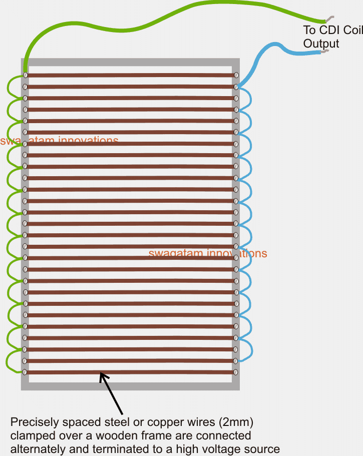
The output from the above linked high voltage generator (CDI coil) is supposed to be integrated with the below shown mesh trap design:
Making the Electrocution Mesh

The electrocutor mesh trap is made by attaching stiff steel or copper wires inside a sturdy wooden frame, in the above shown manner...the wires are then alternately connected using small pieces of connecting wires.

The common ends of the two alternately arranged mesh assembly is then terminated to the CDI coil or the high voltage generator.

Since the battery used for powering the high voltage generator needs to charged with a solar panel, a simple solar charger circuit becomes imperative, the same may be built exactly as instructed in the following article

https://www.homemade-circuits.com/2012/04/how-to-make-solar-battery-charger.html

The ammeter may be eliminated as it's not so important for the present application.

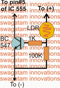
There's another issue that needs to be solved here, the high voltage generator circuit needs to remain switched OFF during the day time while the battery is being charged.

This may be implemented by adding the following simple transistor/LDR circuit with the pin#5 of the IC 555 of the high voltage generator stage.
You'll also like:

  • crop field insect protector solar circuit diagramInsect Light Trap Circuit for Protecting Crops
  • dogbarkcircuitHow to Make Dog Barking Preventer Circuit using High Frequency Deterrence
  • mos rep3 Useful Electronic Mosquito Repellent Circuits Explored
  • ultrasonic dog whistleSimple Electronic Dog Whistle Circuit Explained

Filed Under: Pets and Pests Tagged With: Crops, Farms, Insect, Killer, Protecting, Solar

About Swagatam

I am an electronics engineer and doing practical hands-on work from more than 15 years now. Building real circuits, testing them and also making PCB layouts by myself. I really love doing all these things like inventing something new, designing electronics and also helping other people like hobby guys who want to make their own cool circuits at home.

And that is the main reason why I started this website homemade-circuits.com, to share different types of circuit ideas..

If you are having any kind of doubt or question related to circuits then just write down your question in the comment box below, I am like always checking, so I guarantee I will reply you for sure!


Previous Post: « Solar Insect Repellent Circuit for Protecting Crops in fields
Next Post: How Thyristors (SCR) Work – Tutorial »

Reader Interactions

Questions & Answers

Total Posts: 4
Newest Oldest
Dean M
July 29, 2023 • 3 years ago #144408

Hello, Swagatam

I am searching for a solution to the problem of having my dog urinate on my trash container.

Thinking some sort of conductive mat (which he would be standing on) placed by the container which would allow for a harmless but uncomfortable high voltage shock whenever the circuit between the mat and the container was closed by the urine stream .

Any ideas?

Thank you,

Dean

Reply
SwagatamAdmin
July 30, 2023 • 3 years ago #144415

Hello Dean,
The idea can be quite risky and painful for the dog, since we do not have any means to test how painful the shock can be…therefore it is difficult to figure out a proper circuit to implement this idea.

Reply
isidro
April 13, 2020 • 6 years ago #77849

Dear friend Swagatam: in the circuit, the colector (BC547) go to the pin 4 (reset) (LM555), no to the 5 (voltage control), ¿or no? Saludos desde México.

Reply
SwagatamAdmin
April 13, 2020 • 6 years ago #77857

Dear isidro, pin5 is correct, but pin4 will also work if the pin4 is connected with 10k to positive.

Reply

Need Help? Please Leave a Comment! We value your input—Kindly keep it relevant to the above topic! Cancel reply

Your email address will not be published. Required fields are marked *

Primary Sidebar

My YouTube Channel

Circuit Simulator: Draw and Simulate Schematics

circuit simulator image


Categories

  • Arduino Projects (95)
  • Audio and Amplifier Projects (134)
  • Automation Projects (18)
  • Automobile Electronics (104)
  • Battery Charger Circuits (90)
  • Datasheets and Components (109)
  • Electronics Theory (151)
  • Energy from Magnets and Earth (43)
  • Games and Sports Projects (11)
  • Grid and 3-Phase (20)
  • Health related Projects (27)
  • Home Electrical Circuits (13)
  • Indicator Circuits (16)
  • Inverter Circuits (98)
  • Lamps and Lights (161)
  • Meters and Testers (72)
  • Mini Projects (28)
  • Motor Controller (68)
  • Oscillator Circuits (30)
  • Pets and Pests (15)
  • Power Supply Circuits (91)
  • Remote Control Circuits (50)
  • Security and Alarm (65)
  • Sensors and Detectors (107)
  • SMPS and Converters (46)
  • Solar Controller Circuits (62)
  • Temperature Controllers (44)
  • Timer and Delay Relay (51)
  • Voltage Control and Protection (44)
  • Water Controller (37)
  • Wireless Circuits (31)


Subscribe to get New Circuits in your Email


Other Links

  • Privacy Policy
  • Cookie Policy
  • Disclaimer
  • Copyright
  • Videos
  • Sitemap

People also Search

555 Circuits | 741 Circuits | LM324 Circuits | LM338 Circuits | 4017 Circuits | Ultrasonic Projects | SMPS Projects | Christmas Projects | MOSFETs | Radio Circuits | Laser Circuits | PIR Projects |


Recent Comments

  • Swagatam on Adjustable Voltage Regulator Circuit using LM324 IC with Over Current Protection
  • Swagatam on Inverter Circuit with Feedback Control
  • Swagatam on Inverter Circuit with Feedback Control
  • Swagatam on Proximity Detector IC CS209A Pinouts – Datasheet Explained
  • PRAFUL WANDHARE on Proximity Detector IC CS209A Pinouts – Datasheet Explained

Social Profiles

  • Twitter
  • YouTube
  • Instagram
  • Pinterest
  • My Facebook-Page
  • Stack Exchange
  • Linkedin

Calculators

  • ZVS Induction Heater + Tank Calculator Tool
  • Zener Diode Calculator
  • Wire Current and Thickness Calculator (Ampacity Calculator)
  • Voltage Divider Calculator
  • Transistor Base Resistor Calculator
  • Transistor Astable Multivibrator Calculator
  • TL431 Calculator
  • Solar Panel, Inverter, Battery Calculator
  • Ferrite Core Air Gap Calculator Tool
  • Parallel MOSFET Calculator Tool: How to Connect MOSFETs in Parallel Safely
  • LC Resonance Calculator for EV Battery Charger Circuits
  • LED String Series Resistor Calculator
  • PFC (Power Factor Correction) Calculator Tool: 3kW
  • Passive Power Factor Correction (PFC) Calculator
  • LM567 IC Calculator Tool
  • SMPS Flyback Boost Converter Calculator
  • Shunt Resistor Calculator for Ammeters
  • SCR and Triac Gate Resistor Calculator
  • Battery Back up Time Calculator
  • Boost Converter Calculator (Non-Isolated)
  • Bootstrap Capacitor Calculator
  • Buck Converter Calculator
  • Buck-Boost Converter Calculator
  • Capacitance Reactance Calculator
  • DCM Flyback Transformer & Wire Gauge Wire Size Calculator Tool
  • Filter Capacitor Calculator
  • IC 4047 Calculator (Frequency and PWM)
  • IC 4060 Calculator
  • IC 555 Astable Calculator
  • IC 555 Monostable Calculator
  • IC SG3525, SG3524 Calculator
  • Inductance Calculator
  • Induction Heater Inductor and Resonant Frequency Calculator
  • Induction Heater Work Coil Calculator
  • Inverter LC Filter Calculator
  • LC Resonance Calculator
  • LED Current Calculator
  • LM317, LM338, LM396 Calculator
  • NAND/NOT Gate RC Values Calculator
  • NOT, NAND Gate Frequency Calculator
  • Notch Filter Calculator Tool
  • Ohm’s Law Calculator
  • Phase Angle Phase Shift Calculator
  • Power Factor (PF) Calculator
  • RC Filter Calculator
  • Reactance Calculator
  • Sine Table Calculator for SPWM Arduino Code
  • Small Signal Transistor(BJT) and Diode Quick Datasheet
  • SMPS Calculator for Toroidal Ferrite Transformers
  • SMPS Flyback Transformer Calculator – Design by Target Duty Cycle
  • TL431 Calculator
  • Op-Amp Hysteresis Resistor Calculator

© 2026 · Swagatam Innovations