As the name suggests a preamplifier circuit pre-amplifies a very small signal to some specified level that can be further amplified by an attached power amplifier circuit. It basically acts like a buffer stage between the input small signal source and a power amplifier. A preamplifier is used in applications where the input signal is too small and a power amplifier is unable to detect this small signal without a preamplifier stage.
In this post I have explained 5 preamplifier circuits which can be quickly made using a couple of transistors (BJTs) and a few resistors. The first idea is based on the request presented by Mr. Raveesh.
Circuit Objectives and Requirements
- Electronics is my hobby since so many years. Often I will be browsing your website and found many useful projects. I require a favor from you.
- I have a FM transmitter module which works on 5 volts DC with provision to connect from Computer through USB or from audio out from any other device through 3.5 mm audio jack.
- The module works great in computer USB mode with great signal strength, quality and coverage. But when I connect the same through audio input jack from DTH set top box the signal strength becomes weak even with full volume in both set top box and FM module. I think the audio signal level from set top box is not sufficient for the FM module.
- Please suggest me a good quality stereo audio small signal preamplifier circuit which can work from 5 or 6 volts single supply, that would not load the set top box, preferably using good low noise op-amp with detailed circuit and parts label.
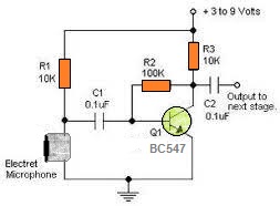
1) Preamplifier using two Transistors
A simple pre-amplifier circuit can be very easily built by assembling a couple of transistors and some resistors as shown in the following figure:
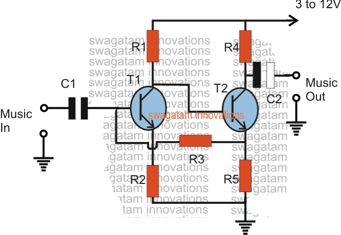
The circuit is a simple two transistor pre-amplifier using a feedback loop for enhancing the amplification.
Any music as we know is in the form of a consistently varying frequency, therefore when such a varying input is applied across the indicated C1 end terminals, the same is delivered across the base T1 and ground.
The higher amplitudes are processed normally and is reproduced with a potential that's approximately equal to the supply voltage, however for the lower misc amplitudes T2 is allowed to conduct at the higher ratio which is allowed to pass to its emitter.
At this time when the actual enhancement of the music is implemented by transferring this accumulated higher potential back to the base of T1 which correspondingly saturates at a much optimal rate.
This push pull action ultimately results in an overall amplification of an insignificantly small music or data input into a significantly larger output.
This simple circuit enables boosting extremely small or minimal frequencies to an appreciably bigger outputs which can be then used for feeding lager amplifiers.
The discussed circuit was actually popularly used in old cassette type playback recorders in their preamp stages for boosting the minute signals from the tape head so that the output from this small amplifier became compatible for the attached high power amplifier.
Parts List
- R1 = 22K
- R2 = 220 ohms
- R3 =100k
- R4 = 4K7
- R5 = 1K
- C1 = 1uF/25V
- C2 = 10uF/25V
- T1/T2 = BC547
Adjustable Preamplifier Circuit
This useful preamplifier circuit is an enhanced version of the above design. It has a voltage gain which can be set at any level between five and one hundred times by using a feedback resistor of the appropriate value.
The input impedance is high, being typically about 800K and a low output impedance of around 120 ohms is obtained.
The noise and distortion produced by the circuit are both very low.
A maximum output signal level of about 6 volts peak to peak can be handled before clipping occurs.
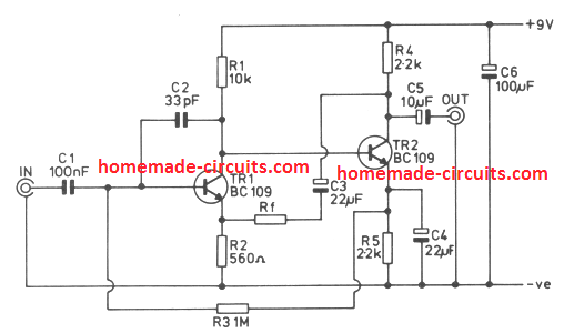
The figure shows the circuit of the unit, and this is a straight Forward two transistor, direct coupled arrangement, with both transistors being used in the common emitter mode. R2 provides local negative feedback over Tr1, and provides a convenient point tn which overall negative feedback can be applied to the circuit.
This feedback is obtained from the collector of Tr2 via D.C. blocking capacitor C3 . and the value of RF determines the amount of feedback that is applied to the amplifier. The lower the value of this component the more feedback that is applied, and the lower the closed loop voltage gain of the unit.
The required value of Rf is found by multiplying the required voltage gain by 560. Thus, a voltage gain of ten limes, for example, requires Rf to have a value of 5.6k.
It is recommended that the voltage gain should be kept within the limits stated earlier. C2 rolls of the high frequency response of the amplifier, and is necessary as instability might otherwise occur.
The upper -3dB response of the unit is still at about 200kHz even if the amplifier is used at a voltage gain of hundred times. When used as lower gains the upper -3dB point is pushed proportionately higher. The lower -3dB point is at approximately 20 Hertz incidentally.
Another Transistorized Preamp design
This is a high impedance input 2 stage preamplifier that features an adjustable voltage gain, from 1.5 to 10. This gain can be varied by setting up VRI and becomes handy where the MIC sensitivity required to be varied often.
As shown above, the circuit is actually designed for crystal microphones or ceramic cartridges.
Parts List
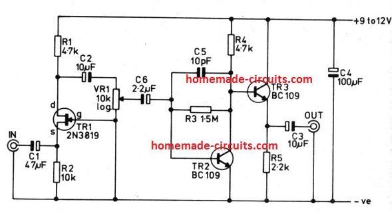
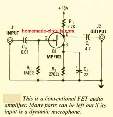
2) Using an FET
The second preamplifier design looks even simpler as it works using a single low cost JFET. The circuit diagram can be seen below.
The circuit is self explanatory, and can be integrated with any standard power amp for further amplification.
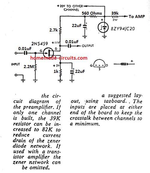
Guitar Preamplifier
It usually becomes necessary to hook up an electric guitar with a mixing panel, a audio deck or a portable studio.
As much as wiring is concerned, that may be not an issue, however matching the high impedance of the guitar component with the low impedance of the line input of the mixing panel does becomes an issue.
Even the unsuspecting high impedance inputs of those units aren't well suited for the guitar output. As soon as the guitar is plugged into this kind of input, you hardly see a signal feasible for the panel or deck to process.
It might be likely to attach the guitar to the (high-impedance) mic input, however that is commonly way too sensitive for the function, which leads to clipping of the guitar signal too easily.
The matching amplifier introduced in this article answers these difficulties: it features a high- impedance (1M) input that will stand up to voltages of over 200 V. The output impedance is fairly small. Amplication is X2 (6 dB).
Dual tone control, presence control and volume control are offered. The circuit is designed for input levels of up to 3 V. Over this level distortion rises, but that may be, naturally, a decent outcome having guitar music.
True clipping of the input signal is not going to take place until eventually significantly bigger levels above the minimum guitar specs are utilized. The circuit is powered by a 9-V (PP3) battery through which the circuit pulls a current just around 3 mA.
3) Stereo Preamplifier Using IC LM382
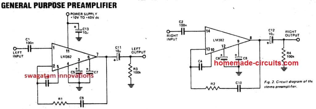
Here;s another nice little preamp circuit using a dual opamp IC LM382. Since the IC provides a dual opamp package two preamps could be created for stereo application. The output from this preamp can be expected to be very good.
Parts List
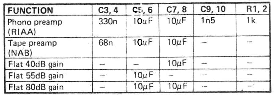
R1, R2 = see the below given table.
R3, R4 = 100K 1/2 watt 5%
C1, C2 =100nF polyester
C3 to C10 = see table
C11 to C13 = 10uF/25V
IC1 = LM382
4) Balanced Preamp
If you are looking for something more sophisticated, you may want to try this balanced preamplifier design. The circuit is elaborately explained in this article which you can refer for your reading pleasure.
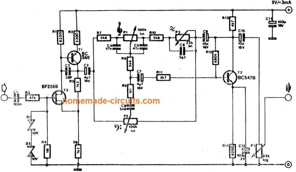
5) Preamplifier with Tone Control
A tone control normally includes bass and treble features for tweaking the dynamic quality of the music.
However, since a tone control also has the ability to amplify the incoming it can be effectively used like an outstanding Hi-Fi preamplfier circuit stage.
This we have a system which works two ways, foe enhancing the tone quality of the music and also preamplifying the music for the subsequent power amplifier stage.
The complete circuit of this fifth preamplifier can be seen below:
UPDATE
Here are a couple of more preamplifier circuits that may interest you.
6) Low Z (impedance) MIC Preamplifier Circuit
The circuit described so far, are of course, only suitable for use with high impedance microphones, and provides insufficient gain for use with low impedance types.
These usually provide an output signal level of about 0.2mV. R.M.S., which is about one tenth of that generated by a high impedance microphone.
The circuit diagram is for a preamplifier that can be employed with low impedance microphones, and should give an output signal of around 500mV. R.M.S.
The prototype was found to work well with both 200 ohm and 600 ohm impedance dynamic microphones, but it should also work well with electret types which have a built-in FET buffer amplifier, but no step-up transformer.
The unweighted noise performance of this circuit is not quite as good as that of the previous circuit, but is still about -60dB referred to 500mV R.M.S.
This circuit is really an adaptation of the second design. The FET input stage uses the common gate mode rather than the common source one.
The common gate configuration gives reasonably good voltage gain together with a low input impedance (a few hundred ohms) which matches the microphone reasonably well.
The only other change in the circuit is that the emitter of Tr2 connects direct to the negative supply rail and there is no feedback resistor here.
This is done to boost the gain of the circuit, which as explained earlier, needs to be about ten times higher for a low impedance microphone.
Zero Noise Preamplifier Circuit
In numerous applications (audio, computing devices, aerospace amplifiers, communications, etc.) an exceptionally low-noise preamplifier stage becomes necessary, and just about any model strategy that could minimize noise by even 1 dB is welcomed with passion by everybody involved.
The circuit demonstrated below provides a fundamental design concept, although not quite ideal, the final results to date are encouraging.
Applying even the highly sensitive measuring devices at our fingertips we still could not determine virtually any output noise signal whatsoever!
Having said that, currently there seems to be still one leftover issue: the gain of the circuit is zero.
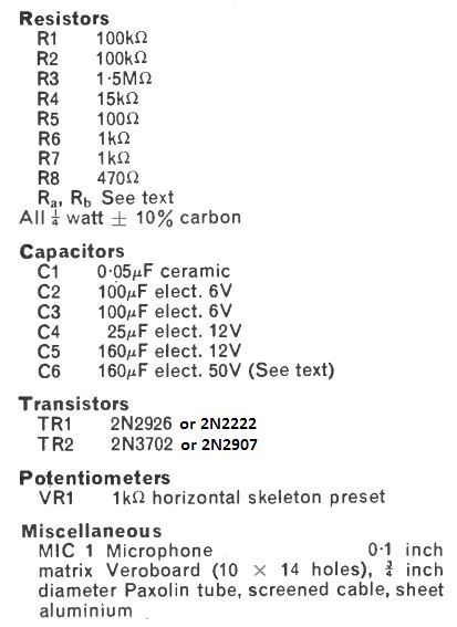
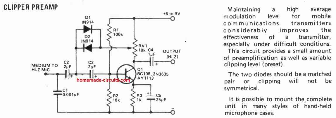
Automatic Gain Control Preamplifier Circuit
This microphone preamplifier features automatic gain control, which maintains the output quality relatively consistent within a broad selection of input ranges.
The circuit is particularly well suited for driving the radio transmitter modulator and enables a large typical modulation index to be accomplished.
This can possibly be applied in power amp systems and intercoms to deliver better intelligibility and make up for varied speakers specifications.
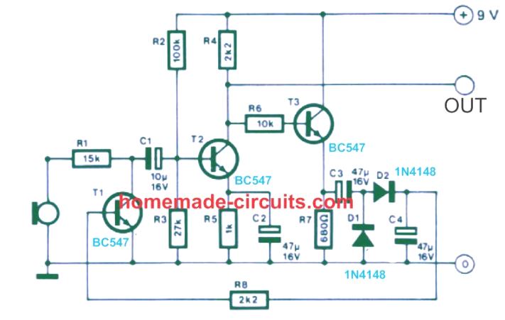
The specific signal amplifier stage is T2, which works in common emitter mode, the output signal being extracted from its collector.
A part of the output signal is supplied by means of emitter follower T3 towards a peak rectifier containing D1/D2 and C4. The voltage across C4 is employed to regulate the T1 base current, that constitutes section of the input attenuator.
At reduced signal concentrations the voltage on C4 is minimal, and T1 pulls very little current.
When the input signal level rises, the voltage on C4 goes up and T1 switches on harder, causing higher suppression of the input signal.
The overall effect is that as the input signal heightens it has to go through an increased degree of attenuation and the output signal thus continues to be reasonably constant across a wide range of input signals.
The circuit is appropriate for inputs having a peak input level up to 1 volt. The microphone could be substituted by a tiny loudspeaker for converting the circuit into an intercom.
1.5 V Preamplifier circuit
While most amplifiers come without adequate input sensitivity and hardly any room within their enclosure, independent low power pre-amplifiers which could be integrated externally may be very useful.
These need to have a bare minimum number of parts and likely be powered with just one dry cell.
The independent 1.5 V preamplifier circuit I have explained below is made up of individual amplifying transistor preceding an emitter follower. DC negative feedback keeps the operating level stable.
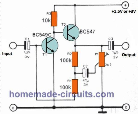
The gain is roughly x 10 to x 20. If the signal source provides impedance of more than 100 k ohms, some amount of gain control is possible through P1.
A reasonably long-term battery back up could be acquired through the use of a couple of 1.5 volt dry cells (in series) rather than one.
If the power falls under 1 volt the amplifier may stop functioning.
Typical dry cells frequently deplete quickly to 1 volt and have to subsequently be thrown away, although it may take longer for each one of two cells to drop to 0.5 volt. Current draw at 3 volt supply will probably be around 450 microamps.
Miscellaneous Preamp Circuits
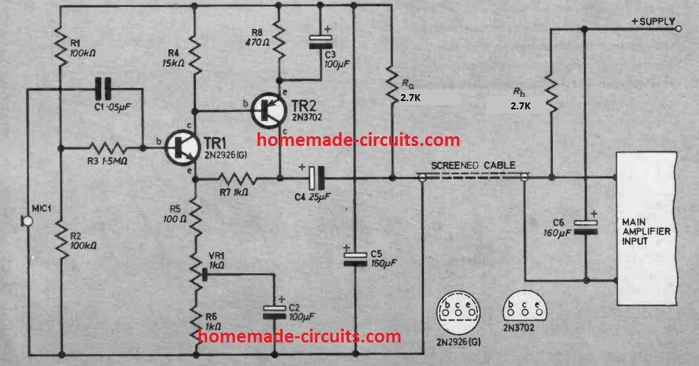
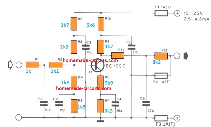
Micro-volt Preamplifier
This preamplifier design can amplify extremely small input signals in the range of microvolts
As a result, the preamplifier must give a significant amount of voltage gain in order to match the output to a hi-fi amplifier, which requires a signal level 1,000 times greater.
Because the input signal may climb at a rate of 6dB per octave, the preamplifier must also offer equalization.
At increasing audio frequencies, nevertheless, low microvolt frequencies are inefficient and require considerably lower roll-off. Q1 and Q2 are utilized in a typical two-stage, direct coupled, common emitter amplifier, with frequency-selective negative feedback provided by C3 and R4.
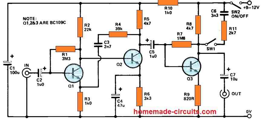
In addition, the midband voltage gain of the input stage is adjusted at around 46dB. With that kind of a low input level, it is apparent that low noise transistors (such as the BC109C) are required to get excellent performance.
It additionally helps to operate Q1 with a low collector current, approximately 200uA. Q3 serves as a low gain common emitter stage, providing extra amplification. R9 adds negative feedback to adjust the voltage gain of Q3, and the given value yields a gain of around 14dB.
Enhanced MIC Preamplifier Circuit for tailored Output Response
In the realm of speech communication, customizing the response of the preamplifier that follows the microphone enhances speech clarity and minimizes unwanted background noise interference affecting the signal.
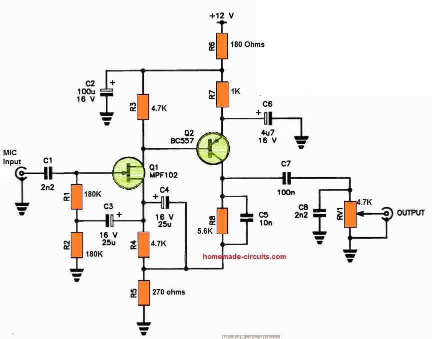
This circuit is engineered to achieve the necessary roll-off slopes below 300 Hz and above 2 kHz. Notably, the higher frequencies experience a considerably swifter attenuation compared to the lower frequencies.
The input stage utilizes a JFET to establish a high-impedance input, which is then directly linked to Q2, a common-emitter stage with bootstrapped feedback to Q1.
The circuit operates with a 12 V power supply and can accommodate both low and high-impedance dynamic microphones.
In instances where a low-impedance microphone is employed, it may necessitate the addition of an appropriate load resistor across the input connector. RV1 is responsible for regulating the output level.

Comments
Hello, awesome collection! But my knowledge in electronics is kind of limited. I want to add a preamp inside my guitar for a cleaner sound. I don’t need EQ. What would you recommend for that?
Hey, thanks, appreciate your interest in tis field.
I would recommend the first simple two transistor preamplifier circuit, since it has been thoroughly tested by me on old tape recorders where it worked superbly as a preamplifier.
Hi dear swagatam
pls I need an adjustable passive preamp circuit for my church.
I need it in a way that I can connect the passive pre_amps input to the output of my audio box amplifier so that I can hear it with my earphone, I want to use it as an in ear monitor.
in summary……… pls help me with a circuit that can reduce the high output signal coming from my box amplifier to my speakers down to a low signal level so I can listen to it with my earphone and the volume can be adjustable too.
Hi Miracle,
I think that can be done through a simple potential divider and a series capacitor.
From the main output of the amplifier connect a series 10uF capacitor, then to the free end of the capacitor attach one outer end of a potentiometer, then connect the other outer end of the potentiometer to the ground of the amplifier, then connect the center wiper end of the potentiometer to one wire of the earphone, connect the other wire of the earphone to ground….
My name is Donald White and my hobby is to help student musicians obtain economical equipment. One of my projects is to use small powered speakers as a practice amp for an electric guitar. The problems are the input of the amp is often stereo and the guitar is mono. I have tried shorting the positive lines together. I suspect there is also an issue with impedance match. I am wondering if a small relatively simple pre-amp could be built as an interface between the electric guitar and the input (line level?). Not looking for any pots as I would like to use the guitar’s controls. I also have a small supply of automotive stereo amps. A pair of sub woofer (TDA7377, 35wx2@4ohm), Radio Shack 40w stereo booster, MEI PA7220 25w x 2. As they are 4ohm stereo could I “bridge” them and result in an out put of 8 ohms? Will the power supply be an issue? I have a bunch of Play Station/game Boy power supplies that can handle over 10 amps. Have you done anything in this area? Any suggestions would be helpful. TKS
Hello Donald,
You can certainly build a couple of preamplifier circuits to interface the amplifier stereo inputs with your mono guitar output.
You can try the first circuit from the above article. You can build two of them and hook up with your guitar output by shorting the C1 ends of the preamplifier. The ground line of the preamplifier will be common to the guitar and the main amplifier.
I am not sure about bridging the amplifier to create an 8 ohm output, since I have never done this practically so far…
Hello! Nice circuits!
But I have a question.
In the second circuit you say:
The lower the value of this component the more feedback that is applied, and the lower the closed loop voltage gain of the unit.
The required value of Rf is found by multiplying the required voltage gain by 560. Thus, a voltage gain of ten limes, for example, requires Rf to have a value of 5.6k.
But then it means that if you want a gain of 100, the resistance will be 56k, a statement that contradicts the statement “the lower the value the more feedback.
Am i missing something here?
Hi, thanks, and glad you liked the circuits.
If you decrease the value of the resistor Rf, the feedback increases but the gain decreases, and vice versa.
So if the feedback is increased, the gain decreases and vice versa.
So by increasing the value of Rf you are decreasing the feedback and increasing the gain….
Let me know if that makes sense or not?
I understand but I’m a little confused because feedback is also used in regenerative radios and the lower the resistance in series with the feedback coil, the higher the amplification… That’s why I thought it’s the same on this circuit. I’ll try them! Thank you for your answer and for the circuits.
You may be correct regarding regenerative receivers, however I think in audio amplifiers such as the above, we use a negative feedback, in which the relationship between the gain and the feedback are inverse, meaning as the feedback decreases, the gain increases, and vice versa.
Thank you!
i liked mpf102 and 12 volt supply based amplifier .
can you share am pre amplifier frequency range upto 400 khz
.
Thank you, and Glad you liked it!
I think most of the above preamplifiers will be able to handle 400kHz because the used BJTs can handle frequencies in MHz…
Thank you, thank you, thank you for your informative web site!
I am a DIY speaker builder and need a good, flat, low noise and low distortion electret mic preamp powered with a 9V battery. Your Adjustable Preamplifier Circuit seems to fit the bill perfectly because I can select gain to avoid overload of line in . Of course it needs the addition of the bias for the electret, but that is easy to implement . I will draw up a schematic with a few minor changes and hope you will critique my efforts.
I am also going to try a 5532 version as well. Will you look at that too? Speaking of 5532’s, will Chinese 5532’s be sufficient for a speaker measurement mic?
And thank you, thank you, thank you again for your efforts here!
Thanks for your feedback, and glad you liked the website.
However, the circuit explained in the above article are not designed by me, they were either referred or contributed by external sources.
I sincerely hope the selected design works for you, as per your specifications.
Also, I am not very good analyzing audio circuits, because simulating them in mind seems difficult to me, so analyzing your 5532 circuit might not be feasible for me, although I wish i could help you with it.
Nevertheless, you can post them here, I hope someone else on this forum might be able to assist you with the analysis.
Damn, I thought I had gone to heaven. I have been on other websites asking for advice but all I got were responses with questions I could not answer. It was, “See how smart I am you dummy.” So there was no real learning on my part. So I am off to see if I can find a down to earth electronics site to answer my questions. Any suggestions? Thanks anyway.
Hello. Excellent page.
I could ask you for a veroboard project of a preamplifier for two electret microphones that has good sound quality. It’s for youtubers. Thank you so much! Greetings from Argentina.
Hi, THANKS YOU SO MUCH. Thanks for answering quickly.
You are most welcome Pablo…
Thank you and glad you liked the post.
I think you can try the following circuit and make two of these to accommodate two MICs:
https://www.homemade-circuits.com/wp-content/uploads/2022/10/electret-MIC-preamp-circuit.jpg
Thank you for your good work, please can you help me with 1000w amplifier circuit diagram? Please Sir.
For a 1000 watt amplifier circuit you can refer to the following article:
https://www.homemade-circuits.com/1000-watt-to-2000-watt-power-amplifier-circuit/
circuit connection like 2kv input connect to filter circuit then detector then proportional counter pcb the anolog output connected to ADC card
i have preamplifier circuit which detect noise please suggest filter circuit for zero noise.my input in 2000v. please provide preamplifier cicruit diagram
Hi, Sorry, I do not have a filter circuit for a 2000 V input supply.
Are there an ic equivalent or replacement for the lm382?
There’s no direct pin to pin replacement for the IC LM382
Hello
Thanks for this very useful website.
I have a question if you could give advice please:
On a car stereo head, which has 4 (line-level) outputs for an amp (FL, FR, RL, RR), I am trying to get another stereo pair, to go into another stereo amp for a third pair of speakers. I am concerned that if I simply take one of the stereo pairs and use passive Y-connectors to get the new pair, each will be quieter, because the power would be shared across two.
So I am thinking of making a small buffer amp, which would take one of the stereo pairs, and duplicate each, but preferably at the same output level as the original signals (or adjustable so this could be achieved). Can I adapt any of the designs you have on this page?
Also – because it’s in a car, the power source would preferably be single-rail – 12vdc.
And – is there a way to measure the output of the car stereo line outs? AC millivolts? So when I make this buffer amp, I’ve got a way to comparatively measure that it’s got a similar output?
I am not a total audiophile who demands ultra-low noise and distortion, but I would be wishing for this buffer to be more-or-less ‘transparent’.
Or is this drop in level not likely to be significant, so therefore I should just use passive Y-splitters?
Hi,
Thanks for your questions, and glad you liked the website.
Yes, you can try one of the above explained preamps for your application.
Most of these will work perfectly with a single 12 V supply input.
Actually I am not an audio expert so it would difficult for me suggest whether or not a Y-splitter would be suitable for your application.
Hello engineer…excellent page…which one would you recommend? I made a homemade Push-Pull class B amplifier, I want to put a microphone input on it.
I don’t remember once I added a Preamplifier to it, the problem was that when speaking the power of the amplifier was lowered.
Thank you Felix, I think you should try the following simpler design:
Heyyy. Could you suggest a microphone amplifier circuit for 12 V?
Hi, you can try the following circuit. The MIC can be any electret MIC:
https://www.homemade-circuits.com/wp-content/uploads/2012/08/MIC2Bamp2BLM386.png
In the 1.5v preamp circuit, can I change the value of P1 to 2k.
Yes, you can do it.
Hi, I’m a licensed Radio Amateur and have many Handheld Radios which I use, some of the Radio’s don’t have the capabilities to turn the Mic gain up. The Microphone / Earplugs connects to both the 3.5mm and 2.5mm Sockets on the side of the Radio’s.
What I’m looking for a Microphone pr-amp Circuit Diagram that I can build that has the capabilities to turn the gain up or down.
I would like to use an Electret Microphone in my Circuit because I have quite a few of them.
Any information would be very grateful.
Thank you in advance.
Hi, thanks for your question!
I think you can try the “1.5 V preamplifier circuit” It has a gain control pot which you can use to adjust the gain.
https://www.homemade-circuits.com/wp-content/uploads/2020/06/1.5-V-preamplifier-circuit.jpg
Hi Swagatam, I would first like to thank you for all the information that you Supply for all of us and you are a great help you provide.
I shall build the circuit diagram you have mentioned and hopefully it will solve the issues I’m having with the Microphone Gain adjustments.
Thank you Kevin! You are most welcome. Let me know how it goes!
Hi there, many thanks for sharing knowledge.
My question is about the common problem when connecting an audio output from a source ( i.e. from a mobile or a mp3 player) to the AUX INput of a head unit in cars. In this case the audio level is so low that you need to max the volume pot of the car unit , and even then the result is not satisfactory.
The problem propably relies into the low output impedance of the mobile (varying around a few hundreds of ohms – earphones ) and the mismatching to the Higher AUX INput impedance usualy several KOhms, and also the inadequate voltage level of the source.
Can you please suggest any kind af a preamp, preferably a tested one for this purpose,that could solve this??
MANY THANKS IN ADVANCE.
Hi, thanks for asking this interesting question. I can definitely help you.
The best small amplifier which can used as a powerful preamplifier the IC LM386 amplifier. You can configure the first or the second circuit from the following article and use it for your application.
LM386 Amplifier Circuit – Working Specifications Explained
hi there. I’m working on a hobby project and looking for assistance in assessing where to bridge two PCBs. Any chance you’d be willing to lend a hand?
Hi, you can explain your problem here, if possible I will try to figure it out.
I have a problem which revolves around Toshiba 5200 and 1943. I assemble amplifiers using the same transistors, and there is no problem. In order to get more output for a Subwoofer set up, I would like to use two more transistors in bridge mode. How do I go about it?
Kindly send me a circuit, so as to understand the set up in a better manner. I will be using 20 O 20 at 3 amps. would that suffice, or should I increase the voltage to 24 0 24, at 5 amps. That would mean heavy heat sinking and fan use also. I do not want to destroy the output transistors. Would 18 0 18 at three amps be sufficient for a subwoofer? 18 x 3 = 54 watts, hence, at least 23 watts?? Your perfectionism is required. Thanking you in advance.
I understand your problem, however I am not an expert with amplifier concepts, so it looks difficult for me to solve your query. I wish I could solve it for you!
Anyone you know who could solve it! Give it a try please!
Sure, if possible I will look for somebody else who can try this…
I have a wireless (RF, i think) subwoofer that connects to a soundbar. Looking for better bass, I bought another (same brand, LG) on ebay — but I can’t get 2 to connect wirelessly to the soundbar at the same time. I’ve disassembled them, and want to locate the node on the master PCB (the one getting the signal) where I can bridge the two. I’m thinking if a trained eye examines the PCBs, you can help me locate where to connect the 2 PCBs (after the preamp circuit, I presume) so that I can feed both amps and drivers the signal. Kindly advise the best way to get you pictures of the front and back of the PCBs. Thank you.
Sorry, this looks difficult. I don’t think I would be able to provide any useful suggestions, because the gadgets you have mentioned are completely unknown to me. Still, if you think I should give it a try then you can upload the images on any “free image hosting site” online and provide the links to me here. I will check them out. Please remember to remove the https while submitting the links.
Thank you, I am glad you liked the post. GE transistors have more gain compared to silicon transistors so definitely you can use them here for increased sensitivity and amplification. However, regarding the exact results, it can be confirmed only with a practical experimentation.