A simple infrared wireless alarm circuit can be built using an 433 MHz RF remote control unit a TSOP based IR sensor, I have explained the procedures in detail.
In a few of the other posts I have discussed regarding these RF remote control modules. For more info you may go through the following relevant article:
In this article we employ one of the above methods, and implement the proposed infrared wireless alarm circuit as I have explained below:
The idea is very simple, the infrared circuit is integrated with the Tx (transmitter) module, such that as long as the IR beam is not disturbed by an intruder the Tx switch is kept deactivated, and the moment the IR beam is interrupted by an intruder, the TX switch is triggered which in turn triggers the remote Rx relay and the associated alarm.
The Transmitter Circuit
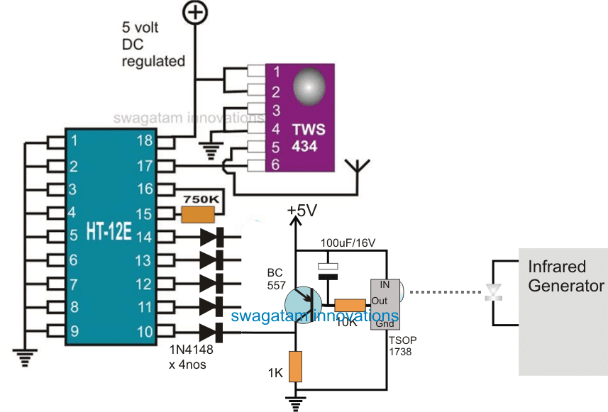
The above configuration depicts the IR wireless alarm transmitter circuit stage set up, wherein the TSW434 forms the standard RF transmitter chip, while the HT-12E is configured as an RF encoder IC.
A IR generator stage can be also seen which is used for generating and focusing an IR beam on the sensor of the IR encoder/transmitter stage.
This IR beam is positioned and stretched across the premise which needs to be guarded.
In the transmitter stage the encoder IC includes 4 inputs all of which require a ground or negative trigger to activate the encoder IC and prompt the TWS to send a corresponding encoded pulse signal in the air within the range of 50 meters.
Depending on the users requirement, only a single stage may be used or all the four stages may be engaged in order to monitor 4 different critical zones needing protection against a possible intrusion or a break in.
The IR sensor stage incorporates a standard TSOP17XX series sensor IC, which is configured with a PNP BC557 transistor amplifier stgae for amplifying the relatively smaller electrical pulses from the sensor to a 5V output.
As long as the IR beam stays focused and incident on the TSOP sensor, the BC557 is held switched ON which ensures a positive potential over the relevant input pin of the encoder IC.
In an event this IR beam is cut-off due a human passing by across the restricted zone, the BC557 is interrupted for that moment which in turn causes a ground signal to appear at the particular input of the encoder pin.
This action instantly initiates the TWS chip to send out a correspondingly encoded pulse in the air which is supposed to be received by the receiver unit or the decoder receiver unit positioned at some desired remote location within the specified radial range, near the user.
The Receiver Stage
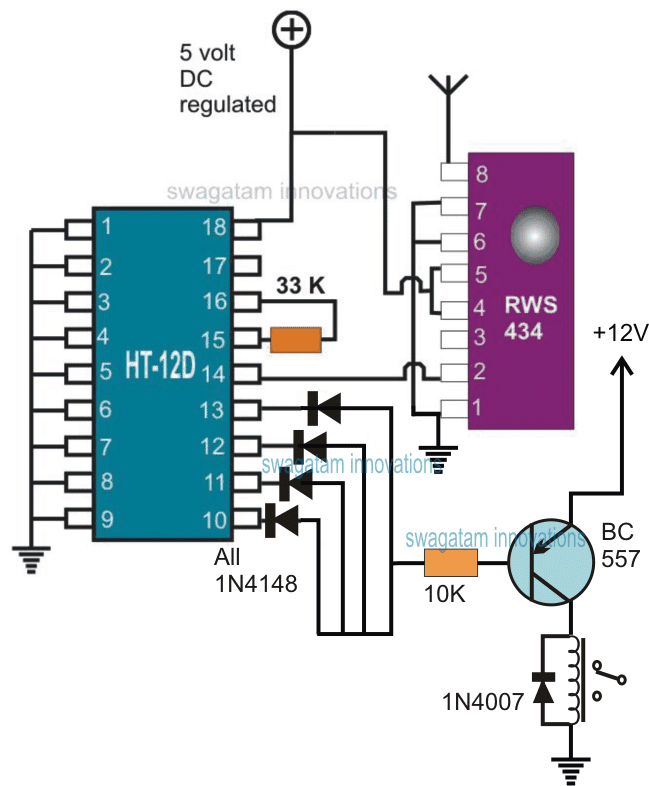
A complementary RF receiver decoder stage can be seen in the above diagram which is configured to receive the signal transmitted by the transmitter stage explained in the previous section.
Here the RSW is positioned to pick up the transmitted signal from the earlier explained TWS IC, and forward the encoded signal to the attached HT-12D decoder IC. This IC then appropriately decodes the received signals, converting them to a logic based signal across its one of the relevant output pins.
Pins 10 to 13 form the output pins of the decoder IC which produces the corresponding logic outputs for an external driver stage.
Here the driver stage is formed through a PNP BC557 and a relay suitably wired for the toggling the connected load which can be an alarm unit.
As may be seen, all the output pins from the decoder IC are made parallel or tied up together and integrated with the relay driver stage.
This makes sure that the relay driver is able to trigger in response to the activation of any of the transmitter input pins which may be configured with a separate TSOP sensor across different critical locations.
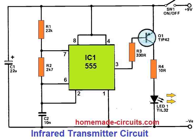
The infrared frequency generator as indicated in the first Tx circuit stage could be built by using a IC 555 wired in its standard astable mode with a frequency set at 38kHz.
The above discussed remote infrared wireless alarm circuit set up can be implemented for monitoring any desired critical location remotely within a radial distance of around 50 meters or more depending on which RF module is employed.


Questions & Answers
Hi Swagatam,
Are the diodes reversed in the schematic for the receiver. I am having a little difficulty in understanding the circuit. Also why do you not use an NPN transistor to operate the relay instead of the PNP transistor? I'm thinking the output from the HT12d is a positive voltage which would drive the NPN transistor. Thanks!
Hi Norman, It is a PNP BJT because the logic changes from an initial high to a low in response to the transmitter switching.
I too had the impression that the logic would be high, but it was tested by one of the readers Mr.Sriram and he found the response to be negative and not positive. you can see the discussion under this article
https://www.homemade-circuits.com/2013/07/simple-100-meter-rf-module-remote.html
Good evening sir, please I cannot figure out the infrared generator for this circuit sir please I need an accesstance
Ebunka, refer to the following article and see how the 555 IC circuit is configured, the same can be used for the above mentioned IR generator circuit….by adjusting the R1 to generate 38kHz
https://www.homemade-circuits.com/2015/01/tuned-infrared-ir-detector-circuit.html
Hi, Mr. Majumdar! Thanks for the great circuit! Can I ask what software you use to create the schematics? The schematics are very easy to understand and look very professional. Thanks in advance! – Brock
Hi Mr.Brock, I use CorelDraw