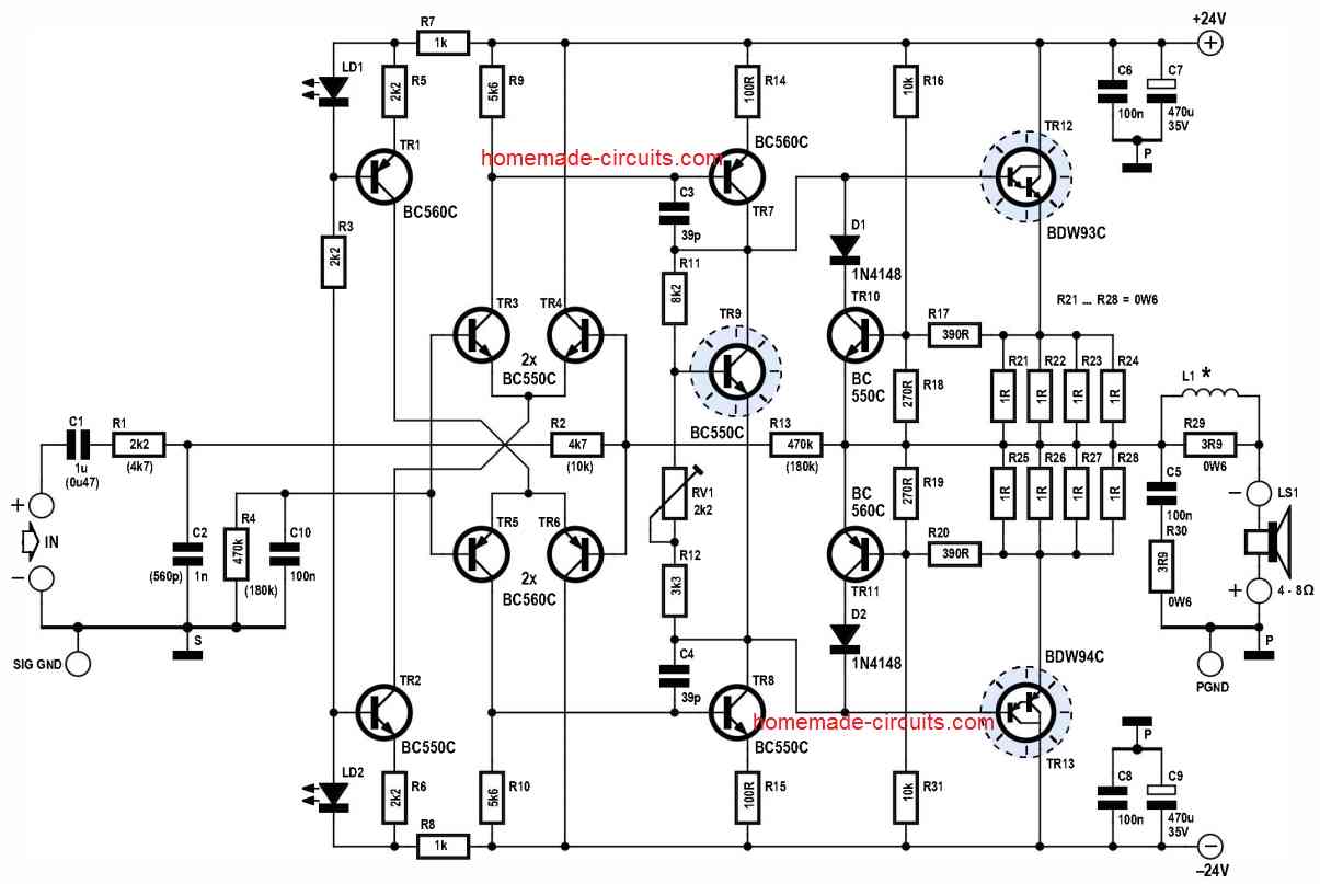
The first schematic describes a 100 watt Guitar amplifier circuit which can be used mainly for amplifying guitar sound and also a public address systems. The next schematic in this article explains yet another guitar amplifier enhanced with fuzz effect generator and treble booster circuits.
To test its ruggedness, the unit is designed without any ancillary equipment like volume control. Furthermore, an appropriate pre-amplifier must be installed beforehand, which is comprehensively I have explained in this article.
Not only does the exterior look tough, but also the performance of this amplifier that manages over 100 watts endlessly using a sine-wave input.
The frequency response is undeniably flat at 50 Hz to 20 kHz, with a total harmonic distortion of less than 0.5% (0.1 W to 80 W).
You can connect multiple speakers from this amplifier on one condition; the total impedance must be equal or more than 4 Ω.
How Does it Work
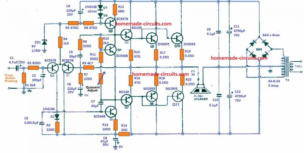
Referring to the above schematic, the guitar power amplifier amplifier employs a quasi-complimentary symmetry, output phase and a differential input phase.
Parallel output transistors are used for an enhanced output capacity while transistors Q6 and Q7 connected in Darlington pair deliver a current gain.
Around 10 mA is provided by the current regulator Q3. This controlled current channels through Q4 and activates the bias for the output stage, and Q5.
The collector voltage at Q5 is determined by its base-emitter voltage. An extremely high voltage gain is present in this transistor because it is operating almost at constant current.
This high gain is attenuated at large frequencies by capacitor C7.
The differential pair Q1 and Q2 controls transistor Q5. As a result of the negative feedback through R7 and R9, Q1 and Q2 function like an error amplifier. So, it attempts to retain the voltage at its two inputs at the bases of Q1 and Q2 constant.
Therefore, the output voltage is made equal to the input voltage multiplied by (R9+R7)/R7.
Resultantly, the amplifier will have a voltage gain of around 22. Changing the value of R7 will allow the voltage gain to vary.
An apt adjustment must also be made to C6 because R7/C6 regulate the lower -3dB point. You must ensure to not change the value of R9.
Quiescent Current Set Up
RV1 which is a 470 Ohms preset, sets the output bias current which is essential to avoid cross-over distortion. This may be done with the help of the following points.
Short the speaker points together, and also the input points together.
Attach, small 100 mA or 50 mA filament bulbs in series with the two supply line inputs (-40 V and +40 V lines).
Now, switch ON power, the bulbs might show high brightness.
Slowly adjust RV1 until the bulbs are shut off or the brightness is reduced to some minimal level.
That's all, the quiescent current setting s complete.
Construction Details
The 100 watt guitar amplifier circuit can be easily assembled because the electronic components are plugged directly on the PCB.
Begin by soldering the electronic parts on the PCB by referring to the plan shown in the below image.
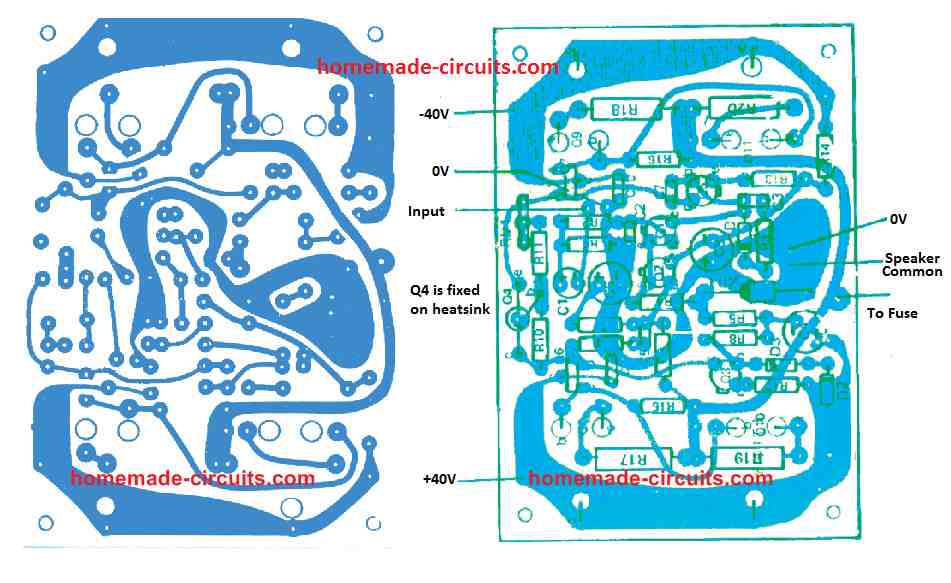
Ensure that all capacitors, diodes and transistors are correctly placed. On Q3 and Q5, metal “fin” type of heatsinks are utilized. Double-check that the heatsink has enough space between the other parts.
Another heatsink that is insulated by mica washers is mounted between Q6 and Q7.
Keep in mind that the heatsink will be a little slanted and the transistor somewhat curved. This is to give space for fastening the heatsink to the “metal side” of the transistors. Always make sure that insulating washers are installed.
The PCB for this guitar amplifier circuit should be fitted against the lid of the metal box and short connecting leads should be connected between the boards to the transistors’ outputs which are plugged on the flip side of this lid.
To make sure the PCB does not touch with the inner face of the lid, countersunk screws and washers are utilized. It is fundamental to install the fasteners at this stage but avoid fixing the board altogether.
Using the countersunk screw and insulating spacers, the heatsink for Q4 must be secured to the lid.
The heatsinks for the output transistors must be installed now, and ensure the transistors are in their right locations. Remember to include the insulating washers.
The short leads must be connected to the emitter, base and collector of the output transistors. This connection to the collectors is done using the transistor mounting screw.
Next, firmly attach transistor Q4 into its heatsink. In the PCB, place the metal joining pins for terminating connections to the output transistors Q8, Q9, Q10 and Q11. The positions of the pin are visibly etched on the PCB overlay.
After that, plug all the leads from the power supply into the PCB. Then, fix the board on top of the leads from the output transistors and fasten them tightly.
Solder the leads from the diverse external connections to the selected pins on the board. Try not to turn the wire around the pins by more than half a turn. Else, when you need to detach it (for some reasons), it will be tough.
Finally, assemble all remaining parts. Ensure the mains earth lead is firmly fixed to the case as it acts as a transformer shield too. The input shield must be earthed to the case directly at the input socket.
Guitar Amplifier Circuit with Fuzz Effect and Treble Booster
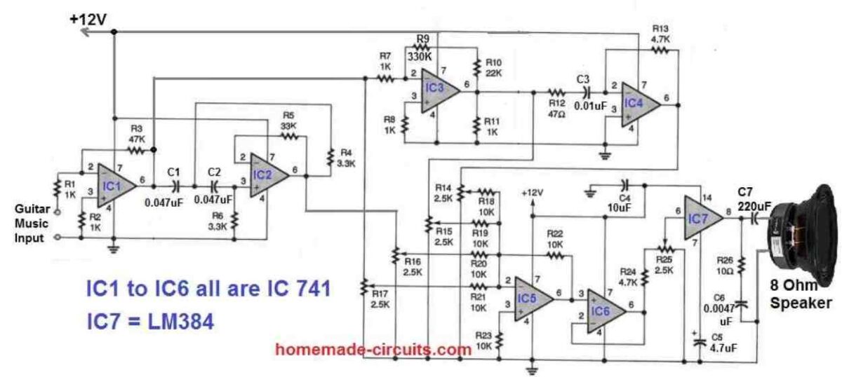
Referring to the above guitar amplifier with fuzz effect and treble booster schematic, we can understand the working of the circuit with the following points:
The output from the guitar is fed to the 741-based preamp 1C1. The output of the preamp is supplied to the mixer directly.
It is also fed to a high-pass filter built around IC2 that acts like a treble booster, and a high-gain amp for clipping, in order to generate the "fuzz." effect. The mixer receives the filtered output of IC2.
The output of the high-gain amplifier is furthermore divided between a mixer and a differentiator.
This generates a spiking waveform from IC3's squared output.
The output of integrated circuit IC4 also connects to the mixer. As a result, the mixer receives dynamic, in-phase inputs that can be clipped, fuzzed, differentiated, or pointy, as well as with an enhanced treble effect.
Setting up several mixer inputs is half the joy of using this fuzz effect enhanced guitar amplifier circuit! The output of the mixer connects to the buffer IC6.
The buffered output connects to IC7, the LM384 power audio amp, through a volume-control potentiometer. Ensure that IC7's unused pins are all grounded.
Finally your guitar skills is displayed to everybody nearby through an 8-ohm speaker, with enhanced fuzz effect and a truly boosted treble output.
Preamplifier Circuit
The level of output signal delivered by most electric guitars will certainly not be sufficient to overdrive the above exlained 100 watt guitar amplifier.
This particular overdriving is a crucial aspect for a perfect, final guitar output.
Therefore, a guitar preamplifier becomes imperative, between the guitar and the main power amp.
The preamplifier circuit described below enhances the small guitar electrical string signals to a higher level.
However, the input stage of the guitar amplifier might clip the output from the preamplifier, if the signal exceeds the required limit.
As a possible solution to the clipping, the gain of the preamplifier could be fixed between 3 and 11 times.
The complete circuit layout is actually quite straightforward.
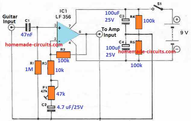
Just one LF 356 delivers the required amplification, that is determined by the ratio of R2 + R3 + P1 to R3 + P1. The input impedance, which, at 1 M, may be pretty high, is specified by R1 since the op -amp includes FET inputs.
This can be a appropriate impedance for the majority of guitar pick-ups. A 9 V battery supplies the power supply which is transformed into a balanced +/ -4.5 V for the op-amp through R4, R5, C3, and C4.
Current draw of this guitar preamplifier will be approximately 5 mA. The design including battery could simply be installed inside a tiny enclosure.
If a plug/socket connectors are fitted on the cabinet, the preamp can easily be hooked up into the guitar.
If this is executed, preset P1 could be substituted with any standard potentiometer to facilitate quick amplification control using the pot knob protruding from the case.
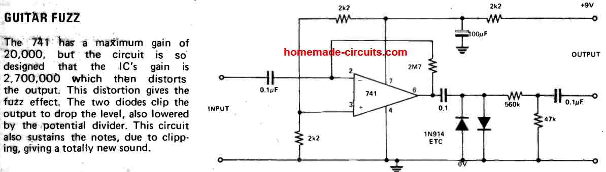
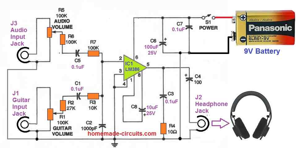
Guitar Fuzz Circuit
The following image shows how to build a guitar fuzz circuit for creating fuzzy sound output from the guitar strings
Improved Guitar Preamp Circuit
The following design was contributed by Mr. Paul, who is one of the avid readers of this blog.
The details are presented below, as sent by Mr. Paul through email:
Circuit Diagram
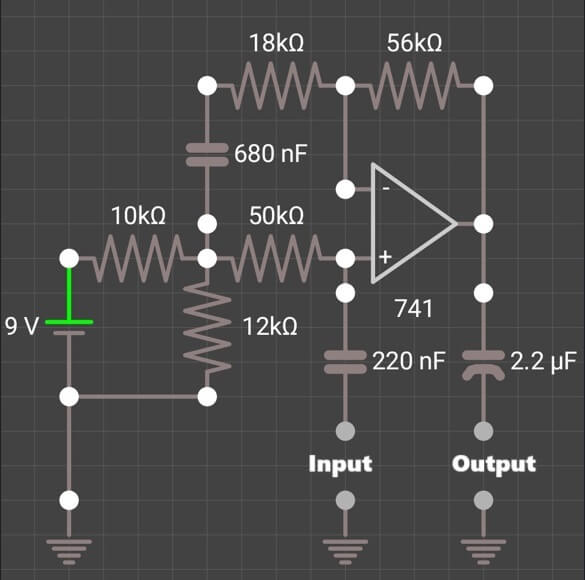
This circuit is designed to boost the weak signal from a guitar (usually a few millivolts) to a higher level which can be processed by effects, amps, or mixers. It is doing this using an op-amp (741) and some clever RC networks.
Let us go stage by stage:
Power Supply Section
The 9V battery powers the whole thing.
The two resistors 10k and 12k form a voltage divider. This gives a virtual ground (midpoint bias) at their junction. So instead of using -9V and +9V we are using 0V and 9V and the op-amp's ground is sort of sitting in the middle of that (like 3.9V or so).
Input Stage (Coupling and Biasing)
The input signal enters through the 220nF capacitor which blocks any DC from entering and only allows the AC signal (the audio from the guitar) through.
Then it goes into the non-inverting input (+) of the 741 op-amp.
This point is also biased via the 50k resistor which keeps the op-amp happy by holding its non-inverting input at the virtual ground.
Op-Amp Amplification Stage
This is the heart of the circuit. The 741 op-amp is configured in a non-inverting amplifier mode.
The feedback loop is formed with:
A 56k resistor from the output back to the inverting input (-)
A 680nF cap and 18k resistor also connected there, forming a tone shaping / frequency filtering network.
This setup decides how much gain and what frequencies get amplified more or less.
Output Stage
The amplified signal comes out through a 2.2µF coupling capacitor which again blocks DC and lets only the amplified AC signal pass to the next stage (amp, mixer, etc.).
Gain of the Amp
Since it's a non-inverting amplifier:
Gain = 1 + (R_feedback / R_ground)
Gain = 1 + (56k / 18k) ≈ 4.1 times
So whatever signal you input, the output will be about 4 times stronger, perfect for a weak guitar signal.
Extras (Tone Filtering)
- The caps and resistors in the feedback network (especially 680nF and 18k) create a low-pass filter, which cuts down the high-frequency noise and makes the tone warmer and less harsh.
- The 220nF input cap also works like a high-pass filter removing low-frequency hums or DC offset.
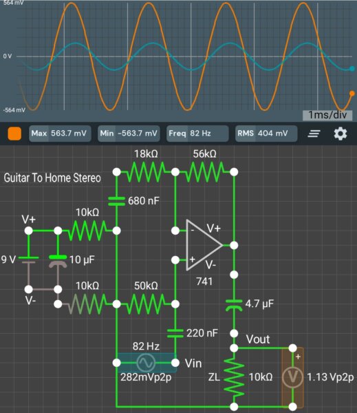
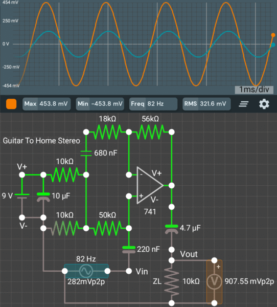
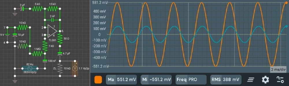
Test Reports
Following are the two circuits that use different ground potentials. Preamp 1 uses 1/2 V+ ground, and has a higher output voltage.
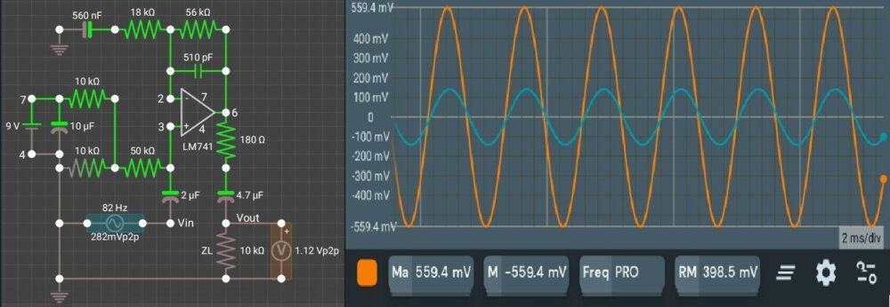
Preamp 2 uses V- ground and has a lower output voltage, because part of the audio input signal is being sent to the inverting input. Both circuits incorporate Power Supply Noise Cancellation.
It should be noted that Preamp 1 must be operated from a separate power supply, if it is used with effects pedals. Effects pedals use V- ground, for the audio input and output.
For those who prefer a preamp that uses a negative ground, and incorporates stabilizing techniques


Questions & Answers
सर क्या आप मुझे 24 वोल्ट से 48 वोल्ट सिंगल सप्लाई ऑपरेटेड क्लास दी या पवम एमप्लीफायर सर्किट या सर्किट डायग्राम के बारे में बता सकते हैं
Noor, you can checkout the following amplifier circuits:
https://www.homemade-circuits.com/4-efficient-pwm-amplifier-circuits-explained/
https://www.homemade-circuits.com/class-d-amplifier-circuit-using-ic-555/
Improved Guitar Preamp Circuit
Virtual ground voltage=(9/22000)X12000=4.91
Measurable gain=.902X((1+(56000/18000))=3.7
This is because 9.8% of my audio input signal appears at the virtual ground, and is sent through the 680nf cap and 18K resistor to the inverting input.
Thanks for your kind contribution and the your valuable feedback…it is much appreciated.
Hai sir
Can you please explain how to convert this 100 Watt guitar amplifier to 200 watt amplifier ?
Hi David, you can increase the supply voltage by using a 36V or 48V transformer and also make sure to replace all the BJTs with 120V BJTs.
Thank you so much sir.
I want to assemble this amp.
can you tell me which 120V BJTs to use and is there anything else that needs to be changed?
David, I would rather recommend you the last design from the following article, since it is a tested design and I was very happy with the results:
https://www.homemade-circuits.com/how-to-make-simplest-100-watt-mosfet/
Thank you sir.
Can you please explain how to convert this circuit to 200watt amp?
I need low noice 200 watt RMS amplifier circuit.
pls help me
David,
The last circuit in the proposed article can handle 200 watts easily, if the input supply is up to 60V DC.
Thank you sir.
When supplying 60V DC should any other changes be made in the values and watt of parts in the circuit? Can you tell me how many Ampere is required for the transformer to make it 200watt?
65V is shown in the circuit.
sir pls give me the instructions.
No problem David, If you divide 200 by 60, it gives around 3.33 amps. So the trafo secondary must be rated at around 4 amps 60V or 50V.
Thank you so much sir…
When supplying 60V DC should I make any other changes be made in the component’s values, component’s voltage, component’s watt and same number of MOSFET in the circuit? or just follow the same parts?
Thanks David, No changes would be required. You can use 60V for the same design without any modifications. However, I would recommend using a PCB for assembling the circuit for guaranteed results. Initially try with lower voltage, maybe 24V, and then slowly increase until 60V.
https://www.homemade-circuits.com/how-to-make-simplest-100-watt-mosfet/
Thank you so much sir for helping me.
Can you suggest one PCB designing free software?
You are welcome David, I earlier used to use CorelDraw for designing PCBs.
sir, can you pls send me the good equalizer and bass treble circuit that you made and satisfied?
David, you can try the first circuit from this article:
https://www.homemade-circuits.com/10-band-graphic-equalizer-circuit-for/
It has been tested by me perfectly.
Thank you very much sir
Thanks for your support
Thank you David, you are welcome!
Thank you very much sir
Hi Swagatam. I need to build mysef a decent guitar amp, but parts here cost a fortune. I have a jrc4558, tda2030, a couple of toshiba 1941 and 5168 power transistors, plus some odds and ends. Can someone assist me in a layman’s schematic for a decent pre-amp and op-amp utilizing these components. It will be much better. Thanks Jacques South Africa.
Hi Jacques,
Did you check the second circuit from the above article, it looks good to me and would perfectly satisfy your requirements.
Let me know your thoughts on this….
Hi,
I would like to assemble the 100 Watt Guitar Amplifier Circuit . Is there any available pcb ready to install the parts for this amp.
Many thanks
Matt
Hi, I appreciate your interest, however, unfortunately we do not have the PCB design for the above project with us at this moment.