• Skip to main content
  • Skip to primary sidebar

Homemade Circuit Projects

Need circuit help? Post them in the comments! I've answered over 50,000!

Blog | Categories | About | Hire Me | Contact | Calculators-online
You are here: Home / Sensors and Detectors / Single Transistor BFO Metal Detector Circuit

Single Transistor BFO Metal Detector Circuit

Last Updated on November 10, 2026 by Swagatam Leave a Comment

The 2nd design below becomes a simple metal detector when it is coupled with a nearby radio receiver that serves as both a detector and an amplifier.
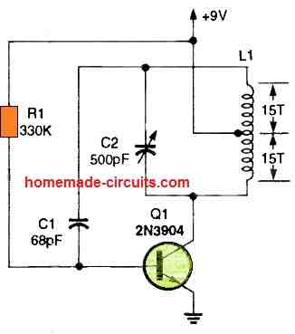
Table of Contents
  • Working Principle
  • Search Coil Winding Details
  • Parts List
  • Troubleshooting Tips
  • Frequently Asked Questions
Single Transistor BFO Metal Detector Circuit

Working Principle

The circuit utilizes a single transistor configured as an RF oscillator connected to a search coil inductor. When powered, it radiates a high-frequency electromagnetic field. A nearby portable AM radio receiver picks up this oscillator signal. By tuning the radio to a local broadcast station or quiet point on the dial and adjusting the variable tuning capacitor, you can hear a low-frequency beat note or fluttering sound from the radio speaker. When a metallic object approaches the search coil, it interferes with the electromagnetic field, altering the coil inductance and oscillator frequency. This frequency shift immediately changes the audible beat note heard through the radio speaker, alerting you to the presence of metal.

Search Coil Winding Details

  • Core / Former: 3 to 4-inch diameter plastic pipe, tube, or non-metallic former.
  • Wire Size: 32 SWG to 36 SWG enameled copper wire.
  • Turns: Exactly 30 total turns of enameled copper wire wound uniformly without overlapping.
  • Center Tap: A center tap connection is pulled out precisely after the 15th turn to create the required three-wire configuration for the oscillator feedback network.
  • Construction Note: Secure the finished winding firmly with adhesive tape or hot glue so that mechanical vibrations do not cause frequency drift during operation.

Parts List

ComponentSpecification / DescriptionQuantity
TransistorNPN RF Transistor (e.g., 2N3904 or equivalent)1
Search Coil (L1)30 turns of 32-36 SWG enameled copper wire on a 3-4 inch former with center tap at 15th turn1
Tuning Capacitor (C1)Variable trimmer or midget air/mica capacitor1
Resistors & CapacitorsStandard biasing resistors and feedback capacitors as per standard BFO oscillator configurationSet
ReceiverPortable AM/MW broadcast radio receiver1
Power Supply6V or 9V DC battery1

Troubleshooting Tips

No sound or beat note in the radio: Check your battery voltage, verify transistor pin connection and ensure the portable AM radio is placed close to the circuit and tuned properly to pick up the oscillator frequency.

Tone does not change when metal approaches: Confirm that search coil center tap is correctly soldered at 15th turn and that all three wire connection to the circuit are secure then.

Drifting or unstable tone: Hand movement or loose leads can introduce stray capacitance keep internal wiring short and mount the circuit inside a stable plastic or non conductive enclosure.

Frequently Asked Questions

Why does this circuit require a portable radio receiver?

The portable radio act as an AM receiver and audio amplifier mixing the oscillator signal with its internal tuning to produce a clear audible beat note without requiring a dedicated on board audio amplifier stage.

Can this circuit be used to scan behind walls?

Yes when the circuit is built into a compact handheld enclosure, then scanning it across plastered or wooden wall allows you to detect hidden metal pipe conduits or nail by listening for pitch change in the radio.

How do you calibrate the detector before scanning?

Turn on the portable radio and tune it near an AM station or quiet frequency then adjust capacitor C1 until a distinct fluttering beat note or whistle is heard from the speaker, indicating the circuit is balanced and ready.

A 3 to 4-inch diameter plastic base or bobbin is wrapped tightly with 30 rounds of wire to create oscillator coil L1. A center tap is pulled after the 15th turn.

It becomes a search head or sensing coil when connected to the circuit via three wire connection then.

If you want to use circuit as a conventional ground sweeping metal detector, then you'll want to mount the search head or sensor in the lower end of a long pole made of wood or plastic. Now the same circuits might be used to find army mines or hidden treasures that contain at least some metal.

Now the whole circuit might be kept in compact container if you want to find metal pipes or wires hidden behind plastered, then wood, or brick structures. Metal detector circuit needs a metal body that will interfere with coil L1's electromagnetic field in order for it to function.

So now the encroaching item affects both the frequency of field and inductance value of L1. Locating metal object might be made easier with a battery operated portable broadcast band radio moved closer to locating circuit.

It let out a piercing cry as soon as it notices change in frequency.

First tune radio to local station so you can hear a low frequency beat or fluttering coming from speaker.

Next adjust C1 to hear the radio's speaker produce low frequency beat or ping.

Beat note changes significantly if the detector circuit happen to be nearer to the hidden metal item then.

Filed Under: Sensors and Detectors Tagged With: BFO, Detector, Metal, Single, Transistor

About Swagatam

I am an electronics engineer and doing practical hands-on work from more than 15 years now. Building real circuits, testing them and also making PCB layouts by myself. I really love doing all these things like inventing something new, designing electronics and also helping other people like hobby guys who want to make their own cool circuits at home.

And that is the main reason why I started this website homemade-circuits.com, to share different types of circuit ideas..

If you are having any kind of doubt or question related to circuits then just write down your question in the comment box below, I am like always checking, so I guarantee I will reply you for sure!

Previous Post: « Metal Detector Circuit Using a Single UJT
Next Post: Simplest Metal Detector Using a Single CMOS IC 4093 »

Reader Interactions

Need Help? Please Leave a Comment! We value your input—Kindly keep it relevant to the above topic! Cancel reply

Your email address will not be published. Required fields are marked *

Primary Sidebar

Categories

  • Arduino Projects (95)
  • Audio and Amplifier Projects (134)
  • Automation Projects (18)
  • Automobile Electronics (104)
  • Battery Charger Circuits (90)
  • Datasheets and Components (109)
  • Electronics Theory (153)
  • Energy from Magnets and Earth (43)
  • Games and Sports Projects (11)
  • Grid and 3-Phase (20)
  • Health related Projects (27)
  • Home Electrical Circuits (13)
  • Indicator Circuits (16)
  • Inverter Circuits (111)
  • Lamps and Lights (183)
  • Meters and Testers (72)
  • Mini Projects (28)
  • Motor Controller (68)
  • Oscillator Circuits (30)
  • Pets and Pests (15)
  • Power Supply Circuits (92)
  • Remote Control Circuits (50)
  • Security and Alarm (65)
  • Sensors and Detectors (123)
  • SMPS and Converters (52)
  • Solar Controller Circuits (63)
  • Temperature Controllers (44)
  • Timer and Delay Relay (51)
  • Voltage Control and Protection (44)
  • Water Controller (37)
  • Wireless Circuits (31)

People also Search

555 Circuits | 741 Circuits | LM324 Circuits | LM338 Circuits | 4017 Circuits | Ultrasonic Projects | SMPS Projects | Christmas Projects | MOSFETs | Radio Circuits | Laser Circuits | PIR Projects |

My YouTube Channel

Circuit Simulator: Draw and Simulate Schematics

circuit simulator image

Subscribe to get New Circuits in your Email

Other Links

  • Privacy Policy
  • Cookie Policy
  • Disclaimer
  • Copyright
  • Videos
  • Sitemap

Recent Comments

  • Swagatam on IC LM393 Complete Datasheet with Circuit Diagram
  • Swagatam on Induction Heater Circuit Using IGBT (Tested)
  • Swagatam on Calculate Battery, Transformer, MOSFET in Inverter
  • Swagatam on Rat Repellent Circuit Diagram
  • Jeff on IC LM393 Complete Datasheet with Circuit Diagram

Social Profiles

  • Twitter
  • YouTube
  • Instagram
  • Pinterest
  • My Facebook-Page
  • Stack Exchange
  • Linkedin

Calculators

  • ZVS Induction Heater + Tank Calculator Tool
  • Zener Diode Calculator
  • Wire Current and Thickness Calculator (Ampacity Calculator)
  • Resistive Voltage Divider Calculator
  • Transistor Base Resistor Calculator
  • Transistor Astable Multivibrator Calculator
  • TL431 Calculator
  • Solar Panel, Inverter, Battery Calculator
  • Ferrite Core Air Gap Calculator Tool
  • Parallel MOSFET Calculator Tool: How to Connect MOSFETs in Parallel Safely
  • LC Resonance Calculator for EV Battery Charger Circuits
  • LED String Series Resistor Calculator
  • PFC (Power Factor Correction) Calculator Tool: 3kW
  • Passive Power Factor Correction (PFC) Calculator
  • LM567 IC Calculator Tool
  • SMPS Flyback Boost Converter Calculator
  • Shunt Resistor Calculator for Ammeters
  • SCR and Triac Gate Resistor Calculator
  • Battery Back up Time Calculator
  • Boost Converter Calculator (Non-Isolated)
  • Bootstrap Capacitor Calculator
  • Buck Converter Calculator
  • Buck-Boost Converter Calculator
  • Capacitance Reactance Calculator
  • DCM Flyback Transformer & Wire Gauge Wire Size Calculator Tool
  • Filter Capacitor Calculator
  • IC 4047 Calculator (Frequency and PWM)
  • IC 4060 Calculator
  • IC 555 Astable Calculator
  • IC 555 Monostable Calculator
  • IC SG3525, SG3524 Calculator
  • Inductance Calculator
  • Induction Heater Inductor and Resonant Frequency Calculator
  • Induction Heater Work Coil Calculator
  • Inverter LC Filter Calculator
  • LC Resonance Calculator
  • LED Current Calculator
  • LM317, LM338, LM396 Calculator
  • NAND/NOT Gate RC Values Calculator
  • NOT, NAND Gate Frequency Calculator
  • Notch Filter Calculator Tool
  • Ohm’s Law Calculator
  • Phase Angle Phase Shift Calculator
  • Power Factor (PF) Calculator
  • RC Filter Calculator
  • Reactance Calculator
  • Sine Table Calculator for SPWM Arduino Code
  • Small Signal Transistor(BJT) and Diode Quick Datasheet
  • SMPS Calculator for Toroidal Ferrite Transformers
  • SMPS Flyback Transformer Calculator – Design by Target Duty Cycle
  • TL431 Calculator
  • Op-Amp Hysteresis Resistor Calculator

© 2026 · Swagatam Innovations