• Skip to main content
  • Skip to primary sidebar

Homemade Circuit Projects

Need circuit help? Post them in the comments! I've answered over 50,000!

Blog | Categories | About | Hire Me | Contact | Calculators-online
You are here: Home / Oscillator Circuits / Sine-Cosine Waveform Generator Circuit


Sine-Cosine Waveform Generator Circuit

Last Updated on September 22, 2026 by Swagatam 4 Comments

The circuit discussed below is designed to generate precision sine and cosine waveforms, which are perfectly identical with their dimensions, but are 90° out of phase.

Table of Contents
  • How the Circuit Works

There are a variety of applications which often demand a couple of sinewave frequencies which are of the identical frequency, but 90° out of phase.

Simply put, a sine signal and a cosine signal together from a single package.

This kind of signals are widely-used in SSB and quadrature modulation, electronic systems of circles and ellipses and conversions involving rectilinear and polar coordinates.

Sine and cosine signals could be acquired from a quadrature oscillator that includes a couple of integrators configured as demonstrated in the diagram.

In the shown diagram, A1 is wired like a non-inverting integrator, while A2 is rigged in the form of an inverting integrator.

How the Circuit Works

The reason why this circuit would generate a sine and cosine signal might not be quickly evident, nevertheless can be easily described.
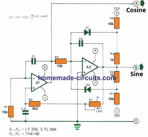
At output B shows up a signal that is a function of time, f(t). Since this is, minus the integral of the signal at A, it is very clear that the signal at A is, minus the differential of the signal at B, that is - df / dt.

In the same manner, the input signal at the integrator A, that is - d2 f / dt2

However, we also find that the signal at the input of A1 is also the output signal of A2.

Therefore, - d2 f / dt2 = f(t)

These conditions are fulfilled through the sine-cosine signals, because if

f(t) = sin ω t (output B)

d(sin ω t) /dt = cos ω t (output A)

d(cos ω t) /dt = d2(sin ω t) / dt2 = -sin ω t = -f(t)

Output A as a result generates a cosine signal and output B a sine signal. P1 can be used to alter the loop gain of the circuit to ensure that it oscillates without any issues or errors.

In case, may be on account of part tolerances, the circuit fails to oscillate at a set adjustment of P1, you may need to to increase its value to 10 k.

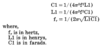
D1, D2 and R4 to R7 are used to stabilize the amplitude of the signal. The sine-cosine frequency rate could be modified by replacing other desired values of capacitor for C1 to C3, by evaluating them through the explained formulas.
You'll also like:

  • 4011 pinout truth table compressedCMOS Astable, Bistable, Monostable Circuits Explained
  • formula for calculating C1 and L110 Easy Op-amp Oscillator Circuit Diagrams Explained
  • 4047 complement gating astable circuit compressedIC 4047 Astable, Monostable Oscillator Circuits
  • colpitts crystal oscillatorUnderstanding Crystal Oscillator Circuits

Filed Under: Oscillator Circuits Tagged With: Cosine, Generator, Sine, Waveform

About Swagatam

I am an electronics engineer and doing practical hands-on work from more than 15 years now. Building real circuits, testing them and also making PCB layouts by myself. I really love doing all these things like inventing something new, designing electronics and also helping other people like hobby guys who want to make their own cool circuits at home.

And that is the main reason why I started this website homemade-circuits.com, to share different types of circuit ideas..

If you are having any kind of doubt or question related to circuits then just write down your question in the comment box below, I am like always checking, so I guarantee I will reply you for sure!


Previous Post: « Simple Triac Phase Control Circuits Explored
Next Post: Solar Charge Controller for 100 Ah Battery »

Reader Interactions

Questions & Answers

Total Posts: 4
Newest Oldest
Jesse Lu
November 7, 2024 • 2 years ago #164948

Hi, I try to use this circuit for emulating the sin-cosine encoder signal output. But I need both +SINE, -SINE, +COSINE, and Negative COSINE. What is the easiest way to generate the -SINE, and – COSINE signal from this SINE/COSINE generator?
Thanks

Reply
SwagatamAdmin
November 8, 2024 • 2 years ago #164963

Hey, I think you can try measuring the signal across the Sine/Cosine outputs and the (+) supply and the (-) supply separately, to get the required +/- results.

Reply
Ronald
August 30, 2026 • 3 weeks ago #212410

I’m trying build sine and cosine to control Roll on a ADI simulated Standby Attitude instrument Makwin 2138-03 old school stuff. level is 0 and left bank 270 deg 90. Right bank 90 deg is 90. 10dc sin sig in roll, 10 dc cosin sig in Roll. Roll sig RTN Roll Null Test. inputs +-10 and +-15 on inputs.
ronpeghall@gmail.com

Reply
SwagatamAdmin
August 31, 2026 • 3 weeks ago #212422

That’s great, so what is your specific requiremenet?

Reply

Need Help? Please Leave a Comment! We value your input—Kindly keep it relevant to the above topic! Cancel reply

Your email address will not be published. Required fields are marked *

Primary Sidebar

My YouTube Channel

Circuit Simulator: Draw and Simulate Schematics

circuit simulator image


Categories

  • Arduino Projects (95)
  • Audio and Amplifier Projects (134)
  • Automation Projects (18)
  • Automobile Electronics (104)
  • Battery Charger Circuits (90)
  • Datasheets and Components (109)
  • Electronics Theory (151)
  • Energy from Magnets and Earth (43)
  • Games and Sports Projects (11)
  • Grid and 3-Phase (20)
  • Health related Projects (27)
  • Home Electrical Circuits (13)
  • Indicator Circuits (16)
  • Inverter Circuits (98)
  • Lamps and Lights (161)
  • Meters and Testers (72)
  • Mini Projects (28)
  • Motor Controller (68)
  • Oscillator Circuits (30)
  • Pets and Pests (15)
  • Power Supply Circuits (91)
  • Remote Control Circuits (50)
  • Security and Alarm (65)
  • Sensors and Detectors (107)
  • SMPS and Converters (46)
  • Solar Controller Circuits (62)
  • Temperature Controllers (44)
  • Timer and Delay Relay (51)
  • Voltage Control and Protection (44)
  • Water Controller (37)
  • Wireless Circuits (31)


Subscribe to get New Circuits in your Email


Other Links

  • Privacy Policy
  • Cookie Policy
  • Disclaimer
  • Copyright
  • Videos
  • Sitemap

People also Search

555 Circuits | 741 Circuits | LM324 Circuits | LM338 Circuits | 4017 Circuits | Ultrasonic Projects | SMPS Projects | Christmas Projects | MOSFETs | Radio Circuits | Laser Circuits | PIR Projects |


Recent Comments

  • Swagatam on Adjustable Voltage Regulator Circuit using LM324 IC with Over Current Protection
  • Swagatam on Inverter Circuit with Feedback Control
  • Swagatam on Inverter Circuit with Feedback Control
  • Swagatam on Proximity Detector IC CS209A Pinouts – Datasheet Explained
  • PRAFUL WANDHARE on Proximity Detector IC CS209A Pinouts – Datasheet Explained

Social Profiles

  • Twitter
  • YouTube
  • Instagram
  • Pinterest
  • My Facebook-Page
  • Stack Exchange
  • Linkedin

Calculators

  • ZVS Induction Heater + Tank Calculator Tool
  • Zener Diode Calculator
  • Wire Current and Thickness Calculator (Ampacity Calculator)
  • Voltage Divider Calculator
  • Transistor Base Resistor Calculator
  • Transistor Astable Multivibrator Calculator
  • TL431 Calculator
  • Solar Panel, Inverter, Battery Calculator
  • Ferrite Core Air Gap Calculator Tool
  • Parallel MOSFET Calculator Tool: How to Connect MOSFETs in Parallel Safely
  • LC Resonance Calculator for EV Battery Charger Circuits
  • LED String Series Resistor Calculator
  • PFC (Power Factor Correction) Calculator Tool: 3kW
  • Passive Power Factor Correction (PFC) Calculator
  • LM567 IC Calculator Tool
  • SMPS Flyback Boost Converter Calculator
  • Shunt Resistor Calculator for Ammeters
  • SCR and Triac Gate Resistor Calculator
  • Battery Back up Time Calculator
  • Boost Converter Calculator (Non-Isolated)
  • Bootstrap Capacitor Calculator
  • Buck Converter Calculator
  • Buck-Boost Converter Calculator
  • Capacitance Reactance Calculator
  • DCM Flyback Transformer & Wire Gauge Wire Size Calculator Tool
  • Filter Capacitor Calculator
  • IC 4047 Calculator (Frequency and PWM)
  • IC 4060 Calculator
  • IC 555 Astable Calculator
  • IC 555 Monostable Calculator
  • IC SG3525, SG3524 Calculator
  • Inductance Calculator
  • Induction Heater Inductor and Resonant Frequency Calculator
  • Induction Heater Work Coil Calculator
  • Inverter LC Filter Calculator
  • LC Resonance Calculator
  • LED Current Calculator
  • LM317, LM338, LM396 Calculator
  • NAND/NOT Gate RC Values Calculator
  • NOT, NAND Gate Frequency Calculator
  • Notch Filter Calculator Tool
  • Ohm’s Law Calculator
  • Phase Angle Phase Shift Calculator
  • Power Factor (PF) Calculator
  • RC Filter Calculator
  • Reactance Calculator
  • Sine Table Calculator for SPWM Arduino Code
  • Small Signal Transistor(BJT) and Diode Quick Datasheet
  • SMPS Calculator for Toroidal Ferrite Transformers
  • SMPS Flyback Transformer Calculator – Design by Target Duty Cycle
  • TL431 Calculator
  • Op-Amp Hysteresis Resistor Calculator

© 2026 · Swagatam Innovations