In this post I have explained how to make a simple windmill generator circuit which can be used for charging batteries, or for operating any desired electrical equipment, all through day and night, free of cost.
Solar Panel vs Windmill
One of the biggest drawback of solar panel electricity is that it's available only during the day time and that too only when the sky is clear. Furthermore, the sun light being at its peak only during midday and not throughout the day makes its harnessing very inefficient.Contrary to this a windmill generator which depends on wind power appears to be much efficient because wind is available all through the day and does not rely on seasonal changes.
However a windmill generator may work with greatest efficiency only if it's installed or positioned on specific regions such as on higher altitudes, near sea or river shores etc.
For a homemade windmill generator to be most efficient one must position it on the roof top of the house in order to get the highest possible wind speed efficiency, the higher the better.
It's said that over 100 meters from ground wind speeds are the maximum and it's active all through the year non-stop, so that proves, higher the altitude better the wind efficiency.
Designing a Windmill Generator
A simple windmill generator circuit concept presented here can be built by any hobbyist for charging small batteries at home, completely free of cost and with negligible efforts.
Bigger models of the same can be tried for achieving greater power outputs which may be used for powering small houses.
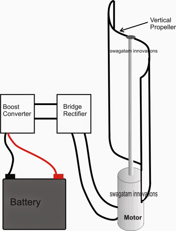
Principle of Operation
The principle of operation is based on a traditional motor generator concept where a permanent magnet type motor's spindle is integrated with a turbine or propeller mechanism for the required harnessing of wind power.
As may be seen in the above diagram, the employed propeller or the turbine structure looks different. Here a twisted "S" shaped propeller system is used which has a distinct advantage over the traditional airplane type of propeller.
In this design the turbine rotation does not rely on the wind directions rather responds equally well and efficiently regardless from which side the wind may be flowing, this allow the system to get rid of a complex rudder mechanism, which are normally used in conventional windmills in order to keep the propeller self adjusting its front position in line with the wind flow.
In the shown concept the motor connected with the turbine keeps rotating with maximum efficiency no matter from which side or corner the wind may be appearing, which allows the windmill to be extremely effective and active all through the year.
Integrating an Electronic voltage Regulator
The electricity generated by the rotation of the motor coil in response to the torque from the turbine can be used for charging a battery or may be for driving an LEd lamp or any desired electrical load as per the user preference.
However, since the wind speeds could be fluctuating and never constant, it may be imperative to include some kind of stabilizer circuit across the output of the motor.
Using a Buck Boost Converter
We can solve the issue by adding a boost or a buck converter circuit as per the specs of the connected load.
But if your motor voltage specs is slightly higher than the load and if there's ample wind, you may exclude the involved boost circuit and directly connect the windmill output with the load after the bridge rectifier.
In the diagram we can seen a boost converter being employed after rectifying the windmill electricity through a bridge rectifier network.
The following image explains the details of the involved circuits, which are also not so complex and may be built using most of the ordinary components.
Circuit Diagram Setup
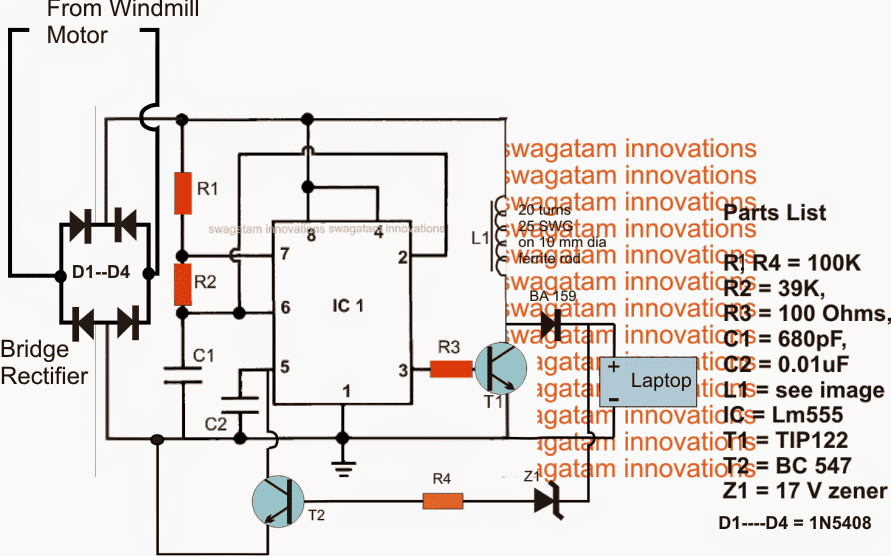
The above image shows a simple boost converter circuit with a feedback error amplifier regulator stage. The output from the windmill is suitably rectified by the associated bridge rectifier network and fed to the IC 555 based boost rectifier circuit.
Assuming the average windmill motor output to be around 12V, the boost circuit can be expected to boost this voltage to upto 60V+, however T2 stage in the circuit is designed to restrict this voltage to a specified stabilized output.
The zener diode at the base of T2 decides the regulation level and can be selected as per the required load restrictions specs.
The diagram shows a laptop battery being attached for charging from a windmill generator, other types of batteries may also be charged using the same circuit, simply by adjusting the value of the T2 zener diode.
Alternatively the number of turns of the boost inductor can also be altered and tweaked for acquiring other voltage ranges, depending upon the individual application specs.
Video:
The following video shows a small windmill set up in which a boost converter can be seen attached with a motor, and converting low power output from the motor to illuminate a 1 watt LED.
Here the motor is rotated manually with fingers, so the results are not so good. If the set up is attached with a turbine then the outcome can be much more enhanced.
Another Video Clip which shows a small motor with an attached gear box generating sufficient energy to illuminate a 1 watt LED brightly. This motor could be configured with propellers and used in high wind conditions for charging a Li-Ion battery or any preferred battery:
Using LTC1042 IC
The latest IC LTC1042, a 12V DC permanent magnet motor, as well as a low-cost power FET may be used to build a basic wind-powered battery charger. The voltage output is equivalent to the RPM of the DC motor, which is utilized as a generator. The LTC1042 controls the voltage output and complete the following necessary tasks:
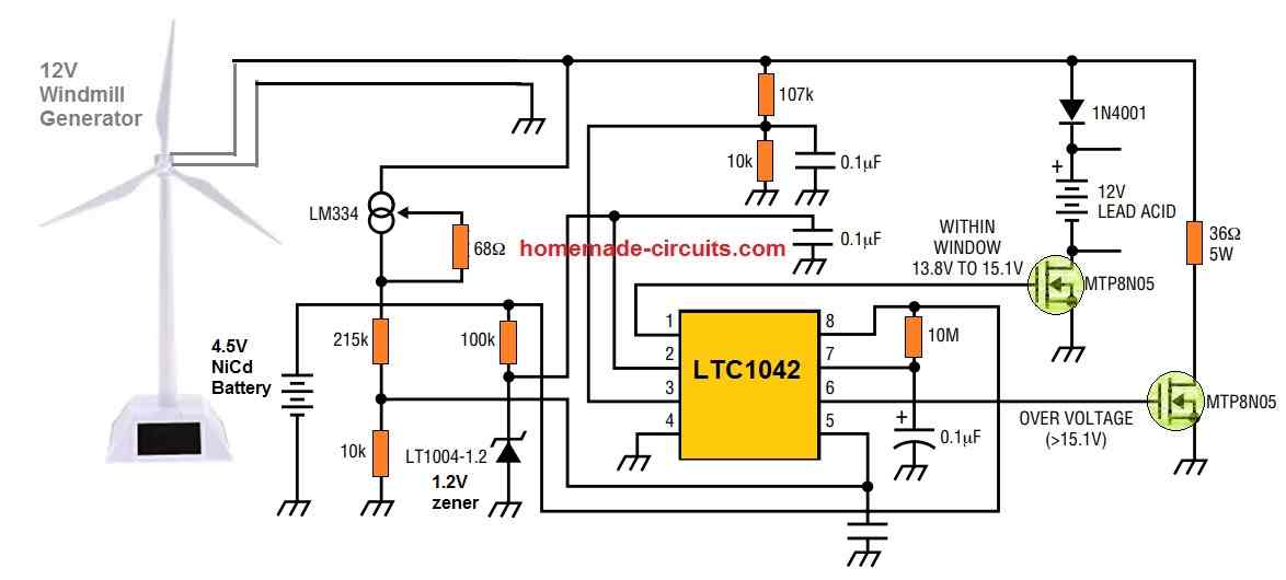
- The control circuit is operational and the NiCad battery is charged by means of the LM334 current source whenever the windmill generator voltage output is lower than 13.8V. The lead-acid battery in this situation isn't getting any current.
- The 12V lead acid battery begins charging at a rate of around 1A/hour as soon as the generator voltage output gets between 13.8V and 15.1V. (restricted by the power FET).
- If the generator voltage increases over 15.1V (due to high wind speed or a completely charged 12V battery), a fixed 36 ohm 5 W load gets switched by the extreme right side MOSFET, restricting the generator RPM and preventing any possible damage.
- Where wind energy is abundant, for example in aboard yachts or remote radio repeater locations, this charger can be utilized as a remote source of energy. In contrast to the solar panels, this device may be used in inclement weather and at also during night.



Questions & Answers
Good morning dear sir, I thank you for the support,
24v motor will be connected to the windmill, instead of wind.
then, I want to convert the windmill which is 3phase connection to the
rectifier diode to make the 24v flooded battery charge well.
Adebanji, to convert 3 phase AC to DC, you can use the following bridge rectifier configuration…
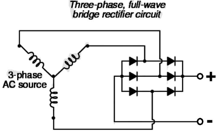
Good afternoon dear Swagatam thanks for the support rendered, ls I need this explanation on our previous discussions about wind generator that powered by DC motor. now, you mentioned buck converter to boost the capacity, I have 3000w 3 phase wind turbine generator and I also have DC motor 24v and 2 batteries with 24v out from it, now the dc motor will pull the 3 phase generator, along the lines there is rectified diode, I believe the power that comes out from the diode must have too much for 24v flooded batteries, that what brought about buck converter right.
Now, 1)pls what capacity or wattage that can be use to charge the flooded batteries?
2)pls can I get diagram to follow as guide for this work?
3)can it be use at home to solve electricity issue in my apartment? pls, pls🙏🙏🙏
Hello Adebanji,
There’s some confusion here. What will be connected with the windmill: the generator or the 24V motor?
Please elaborate on the windmill configuration using the mentioned parameters.
Thanks Swagatam,
I can understand the analysis now,
I will still call for help when it’s the time.
No problem Adebanji, feel free to get in touch whenever you want, I am always happy to help!
good morning.
This circuit starts working from what voltage with AC generator and in DC?
Is it a pwm or mppt circuit?
What is the maximum power at 12v?
If there is no wind, does this circuit drain the battery?
Thank you very much for your attention.
Hello,
The second circuit starts working from 5 V input AC
It is a PWM circuit
Power will depend on the maximum current of the motor and the rating of the boost transistors.
Battery will not drain when there is no wind.
Hello Sir,
We have an open turf (ground) of around 100 ft x 50 ft. Ample wind is available because only a few obstructions are nearby. 12 halogen lights are installed at a height of 30 ft from the ground. Can we use wind energy to light up these halogen lights?
Hello Makrand,
That is definitely possible, but for illuminating 12 halogen lamps you would require a massive windmill system.
We can use 100 watt LED lights instead of 1000-watt halogens. Can we have a simple wind mil system for it?
Even if you use 100 watt LEDs, 12 LEDs would mean 1200 watts which will still require a very heavy windmill system.
Sir, I want to construct home purpose 1000 w , vertical axis wind power generation system, using multiple cups in a vertical shaft of 5 feet hight, shaft supported at top for preventing vibrations during rotating.
battery & inverter already installed at my home.
Plz guide me about which type of motor is to be used as generator, battery specifications for this requirement & connections from generator for battery charging .
Thanking you in anticipation
Vijay soni, Ambajogai Dist.beed Pincode 431517
Plz guide me
Hi Vijay,
Can you please specify how much voltage output do you require for the inverter. Is it 12V, 24V, or 48V? Once I know this I will try to help you out.
Microtek inverter specification are as below
Model Number: UPS EB 1200VA, Technology Used, Micro Controller Based Intelligent Control Design
Voltage: 100V~300V x 200V – 230V, Back Up Time: 7 hrs
Protection: overload, deep discharge, short-circuit, reverse polarity
Frequency: 10.5 – 14.2 x 180V~300V
Battery can be installed as per your advice.
Plz communicate
Can the inverter work with a 48V battery? I would recommend a 48V inverter so that a 48V 30 amp PMDC motor can be used as the DC generator to charge the 48V battery. If a 24V battery is used the current required of the motor would be 60 amps, and for a 12V battery the current specification of the motor would need to be 120 amps. So, as the battery voltage decreases the current requirement increases which can make the system bulky and complicated, that is why a higher voltage inverter/battery is recommended.
The DC motor generator output can be controlled using a shunt regulator circuit, which I can provide.
Good Afternoon sir,
Can I use the first circuit to charge the lead acid battery..
And in second Circuit the LM334 is it a IC or transistor, I’m finding two types of components on online..
I want to use this circuits for my project by using e bike motor of 100w,24dc,2500rpm.
Hi Satya, yes you can use the 555 circuit to charge a lead acid battery but first make sure you build the boost converter correctly.
LM334 is an IC.
Hello,
What does the ic 555 do in this circuit?
provides frequency pulses to the transistor to enable the boosting
Hello Swag.
How to design a circuit for windmill generator that can run directly any household electrical equipment. I don’t want to use any batteries in the circuit. Suppose the generator total output would be 220 V, 25 A.
Hello Hajazi, for this you can use a 300V /25 amp wind mill motor and turbines and use it directly for the purpose. To control the output at constant 220V you can apply the shunt regulator feature explained in the above article.
WHAT IS THE POWER OF DI TO D4 ?
it will depend on the current delivered by the windmill…should twice of that!
What is the inductance of the inductor?
Thank you.
For my project I have been restricted to use a MOSFET and Gate Driver for switching. Can you please suggest which would work best here?
I can help, but first you will have to provide all the technical details of the project, for example the output voltage from the generator, the voltage required for the load, and the total wattage involved….this will help me to understand the exact design that may suit your requirement
The required output is 3-5 V, and 1A current.
With 3 to 5V you wouldn’t require any boost circuit….you can simply use a 12V 2 amp motor as the generator, and use a 7805 IC for regulating the output at 5V
Yes, I realize that but my instructor has asked me to use a buck-boost converter anyway so as to gain experience.
you can try the concept presented in the following article, and experiment with it
https://www.homemade-circuits.com/universal-ic-555-buck-boost-circuit/
Which mode is the 555 timer being used in?
astable multivibrator
Sir u’re doing great in ur blog keep it up,
sir I want to build 100kva inverter ,now my question is as follows.
• I want my tras4mer rating to be 1500watts and 1800amperage.
• I will be using 8 irfp2907 mosfets, 4 at the lower side and 4 at the upper side and I want to use 2 tip31 as the driver for both the upper and and lower mosfet.
• I will aiso be using ic4047 as the heart of the inverter which is sine wave.now I want to know if I can be able to generate maximum power of about 1500watts at the output with 12v 30amps battery. And also how many turns or guage I’m I suppose to use at the primary and secondary coil. But if it is not possible to achieve this maximum power then guide me on how to achieve this maximum power rate.
• Can all mosfets be attached on heat sink without an insulator then if it can’t be what are other insulator situable for mosfet apart from mica insulator cos I can’t get reach of thermal paste. Pls I need quick response
1500 watt with 1800amps? I think you meant to say 180amps. Still that sems incorrect, if you divide 1500/180 gives 8V…so battery must be 8V for that
If it is 180 amps how can a 30 AH battery deliver it? for 180 amps you would need a 1000AH battery or at least a 500AH battery
better to use separate heatsinks for the mosfets on the two channels of the inverter, on individual channels if parallel mosfets are employed then those can be connected without isolators…
Sir i have an idea, can i use a Motor Bike generator? then i want to install two windmill and one solar, please do you have a circuit that the three can work with the principle of charging one battery?
Deogratia, you can simply add separate bridge rectifiers with each of the sources and join their outputs in common with the battery.
for cut off you can perhaps add a single controller circuit between the battery and the bridge outputs.
Sir i can't find a dynamo to construct this circuit… can i use a dc motor from a car windscreen wipper?
Yes, you can try that…
Dear sir,
Your explanation is very simple,that is very good for learning.But,I have a problem.What are the features,configurations of the wind motor/generator set.As the same time hybrid also what are the features of the generator set.Why use DC generation at the hybrid set except the AC.
Thank you for your kind cooperation.
Thank you Chathura, the specifications of the motor can be as per your own preference, and the boost charger specs also could be dimensioned according to the motor specs.
This is not a hybrid generator circuit, for hybrid option yo could refer to this design:
https://www.homemade-circuits.com/2015/09/solar-wind-2-input-hybrid-battery.html
hello sir … can I ask you a quick question ? if I use a 12v dc motor and I use this your circuits how much voltage output can I get …im planing to use this to charge laptop
you will get 12V if the rotation speed is at the optimal level…
Hello,
I am final year engineering student. I am building a project that will combine solar power and wind power to charge a battery for 100Watt AC power inverter circuit. Can you please help me with it. Can you please send me available data to my mail address peru5194@gmail.com
Thank you for help.
Hello, you can perhaps go through the following concept and see if it suits your requirement
https://www.homemade-circuits.com/2015/09/solar-wind-2-input-hybrid-battery.html
Good day mr.majumdar. I like your post and also I need that for my brother's project. If I change zener diode to 5v. Can I use that cellphone charger? Im waiting for your response thank you.
DM, yes that's possible, but make sure the motor current is rated sufficiently high and the wind speed will need to be optimal.
Swagatam, you have an interesting strobe circuit which hasn't a comment area I wish to address.I don't know if you have viewed the "atomic flashlight" commercial. Well what I'm attempting to build is the " the strobe light that wards off attackers " circuit. I want to place several on separate(i have built already) pir's around the battery vault I have for my wind generator. I have a sercurity line attached to the vault but…
Hi Cuyler, just now I watched the atomic flashlight video and I found the "square" light impression on the ground quite interesting which could be difficult to achieve using ordinary LED flashlights.
However as far as warding of attackers is concerned it could be probably achieved through ultra high bright LEDs assembled inside prismatic reflectors….the variable strobing effect could be effectively implemented using a IC 555 astble circuit configured in the PWM mode.
Such lights will be quite capable of causing an instant headache for anybody looking at it even for a couple seconds…
i plan on a vawt which spins ccw with a ratchet catch at the base to ensure this. so for the motor i will be using a dc motor from a dc treadmill. do i still need the bridge rectifier? i grew up only using bridge rectifiers on a-c circuits so am i missing something here?
DC motors are actually better suited for generating electricity than AC motors, so I think the article which you read has suggested just the opposite 🙂 please go ahead with your earlier plans and use a DC treadmill motor
Thanks for the most timely reply. Whew i thought I had been doing something wrong for the past 45 years! I read an article about regenetive braking in which the author touted "dc motors do not produce electricity. And then goes on about a-c motors do in this scenario in which HIS a-c motors should be purchased.
If your motor rotational direction is fixed then the bridge will not be required, but if it is not fixed then a bridge would be required for ensuring that the connected battery always gets a supply with a fixed polarity regardless of the motor rotational direction.
good site….
hi, As you have said you used PMDC generator then it generates DC why would you rectify it again?
Actually a developer who has developed his own wind turbine(which has PMDC motor in it) and solar panel the specifications are:
solar panel:
pmax=110W.Vmax=12.25V.Imax=5.79A.Open ckt voltage=21.7V.short circuit current=5.90A.module effeciency=13.3%.No of cells=36.
wind turbine:PMDC,vMax=90V,rpm=2500,current=3.90A.
He gave me the weather forecast details about his location(mostly in punjab) And now he wants a charge controller to charge his 150Ah smps battery. I want to take this as my project and build a final product. But, as i will be performing in lab how to check correctness of my circuit without actually having the solar panel and wind turbine? That is if i have to show it to my proffesors i just cant take them to site i need to show in lab.But i am clueless as to how to start like this? Can i simulate solar or wind V-I characteristics partially(in lab) to show how my circuit could charge the batteries..How do i go with it? After having analysis on wind speed in his location it appears that wind speed is about 3.5 to 4.5m/s max and voltage variation is 7-10V so i need a boost converter here and a buck converter for solar.
What type of charging cycle are you looking for? according to me it would be the same for both the variants just make sure it's switched OFF on full charge.
for a designing a buck converter you'll need to study all the basics first, you can find the relevant articles in this website through the search box, or through other online sites.
thanks.
I want to start my design with a buck converter for 12V 150Ah smps battery. As here i mention smps battery i understand its wet battery so the charging cycle is different for sealed and wet battery hence,i need to have two different charging cycles provision leaving at the choice of consumer can i do this?
But how do i start designing a buck converter for a given rating?
Hi, the above shown windmill design could be rotated clockwise or anticlockwise depending on the wind direction, that's why a bridge is included so that the output is always a single supply DC regardless of the wind direction.
you can perform a lab test by using a variable voltage and current DC power supply as shown in the following diagram:
https://www.homemade-circuits.com/2012/01/how-to-make-versatile-variable-voltage.html
According to me you can use the following buck converter design for both wind and solar inputs:
https://www.homemade-circuits.com/2015/05/5v-pwm-solar-battery-charger-circuit.html
the output volts and current can be adjusted by suitably changing the R9 and R13 values.
hi Disha Karnataki
if you make your project can you please content me i need your help my email is “”awaisraza4848@gmail.com”
thanks in advance
hi swagatam ji how to make a self running magnetic motor can u help it upto 12vdc power
Hi Suman, that's not possible with our level of knowledge…
Can i use toy motor.
If yes, then any specification.
a toy motor may produce extremely small power output
Mr swagatom, can any motor be used or do you need a friction motor
Hello Rager, any motor can be used as long as its output matches the battery specs. Any DC motor can be used.
I need the specification of the generator. Is it available in chadni market?
you can try a small bicycle dynamo for the generator
Always like these type of radiant energy device. Keep posting like that.
thanks for the feedback, I am glad you liked it..