• Skip to main content
  • Skip to primary sidebar

Homemade Circuit Projects

Need circuit help? Post them in the comments! I've answered over 50,000!

Blog | Categories | About | Hire Me | Contact | Calculators-online
You are here: Home / Lamps and Lights / Precision 4-Transistor Automatic Street Light Circuit

Precision 4-Transistor Automatic Street Light Circuit

Last Updated on October 29, 2026 by Swagatam Leave a Comment

In this post we are going to look at a very special and robust design: a purely discrete 4 transistor automatic street light circuit. Many hobbyists ask me why we should use four transistors instead of a simple IC 555 or an op amp. The main reason is that some makers love old school, pure transistor circuits because they do not depend on IC availability and when tuned properly, then a multi stage transistor amplifier gives incredible analog smoothness.
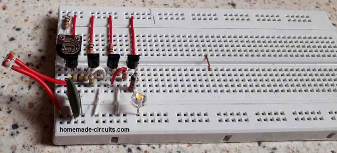
Table of Contents
  • The Benefit of Multi Stage Transistor Network?
  • Components List
    • AC Mains Safety Warning
    • Circuit Diagram
  • Working Explanation
  • How to Calibrate
    • Troubleshooting Steps
    • Prototype Images

Let us investigate into how this multi transistor cascade works and how you can build it without any relay chattering.

The Benefit of Multi Stage Transistor Network?

When you use just one or two transistors, then the shifting from day to night is quite sharp but minor voltage drops or shadows can sometime cause the relay to buzz or chatter.

By cascading four NPN transistors in a direct coupled differential configuration, circuit act like a high gain analog Schmitt trigger.

First two transistor form a sensitive light sensing differential pair that compare the LDR voltage against a stable reference divider, while final two transistors act as a high current totem pole driver for the relay coil. This completely eliminate relay fluttering during slow evening twilight hours.

Components List

To build this 4-transistor automatic street light circuit, gather these parts:

  • Transistors = Four BC547 NPN transistors (T1, T2, T3, T4)
  • LDR1 = Standard Light Dependent Resistor
  • Preset Potentiometer = 100K preset (for precise twilight threshold adjustment)
  • Resistors (1/4 watt, 5% CFR) = 1K, 10K, 47K, and 100K resistors
  • Filter Capacitor = 220uF / 25V electrolytic capacitor
  • Bridge Rectifier Diodes = Four 1N4007 diodes (for AC mains step-down power supply)
  • Relay Flyback Diode = 1N4007 diode (connected across the relay coil to stop back-EMF spikes)
  • Power Transformer = 0-12V, 500mA transformer (or a 12V SMPS adapter)
  • Relay = 12V, 400-ohm coil electromechanical relay
  • Output Load = 220V or 120V AC LED street bulb

AC Mains Safety Warning

Remember that this project connects high voltage 220V/120V AC power lines to relay output contact. AC electricity is extremely dangerous and can cause severe shock or fatal injuries.

Always disconnect power before making any soldering or wiring change, use properly insulated screwdrivers and enclose your finished circuit inside a strong, closed plastic electrical box.

Circuit Diagram
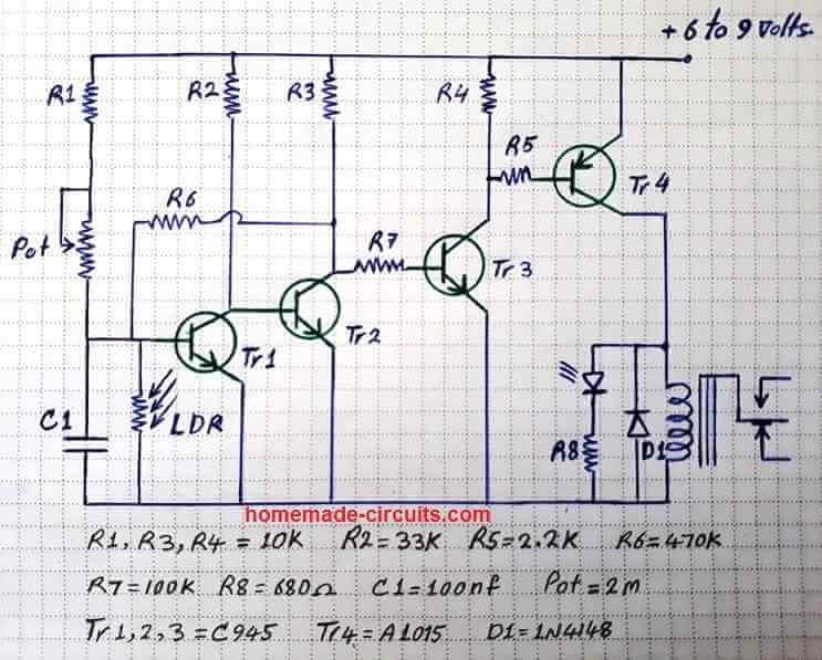
Working Explanation

Let us understand the exact electronics behind this 4 transistor design:

Sensing Stage (T1 & T2): Transistor T1 is connected directly in series with the LDR, forming a voltage divider with your 100K preset. During day, bright light keep the LDR resistance extremely low, pulling the base of T1 high.

When T1 conduct, then it regulates base voltage of the second transistor T2, keeping T2 in a stable cut off state.

Inversion and Amplification Stage (T3): As evening arrives, LDR resistance rise steeply. This causes T1 to begin cutting off which flips state of transistor T3. Because T3 acts as an analog inverter, its collector voltage rise sharply after the twilight threshold is crossed.

Relay Driver Stage (T4): The final transistor T4 receive the amplified signal from T3 and provides high base drive current to pull down 12V relay coil instantly. This multi stage gain ensures that relay snap shut cleanly rather than slowly sliding into position and causing a buzzing noise.

How to Calibrate

Wire all components carefully on your general PCB, making sure transistor collector, base and emitter pins are placed correctly (Flat side facing you: Collector is left, Base is middle, Emitter is right).

  • Connect your 12V power source and turn 100K preset wiper fully to one side.
  • Mimic evening darkness by covering LDR completely with black tape or your hand.
  • Slowly rotate the preset until you hear the relay click firmly, turning on your AC street lamp.
  • Uncover the LDR to let room light hit it, relay should release instantly.
  • Lock your preset using a tiny drop of nail paint.

Troubleshooting Steps

Relay Buzzing at Dusk: This means your gain transistor is oscillating due to slow voltage shifting. Check if filter capacitor (220uF) is properly soldered across the DC supply rails then.

Bulb Stays ON All Day: Your preset threshold is set too tight. Adjust the 100K preset in the reverse direction while exposing LDR to bright sunlight until the relay shut off.

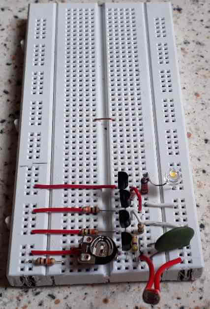
Prototype Images
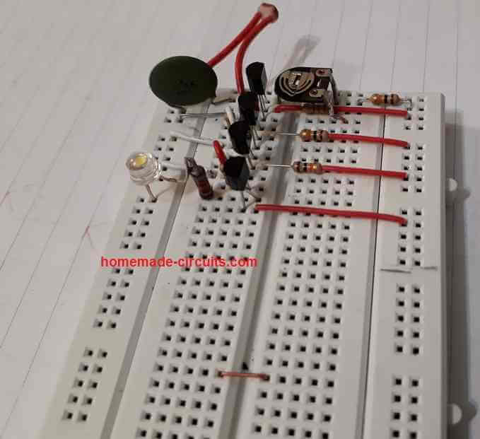
You'll also like:

  • How to Connect a TSOP1738 IR Sensor
  • clap switchClap Switch Circuits with Relay ON/OFF: [Tested]
  • Transformerless Automatic Night Lamp Circuit
  • halloween eyesSound Triggered Halloween Eyes Project – “Don’t Wake the Devil”

Filed Under: Lamps and Lights, Sensors and Detectors Tagged With: Automatic, Light, Precision, Street, Transistor

About Swagatam

I am an electronics engineer and doing practical hands-on work from more than 15 years now. Building real circuits, testing them and also making PCB layouts by myself. I really love doing all these things like inventing something new, designing electronics and also helping other people like hobby guys who want to make their own cool circuits at home.

And that is the main reason why I started this website homemade-circuits.com, to share different types of circuit ideas..

If you are having any kind of doubt or question related to circuits then just write down your question in the comment box below, I am like always checking, so I guarantee I will reply you for sure!

Previous Post: « How to Build a Simple Single Transistor Automatic Street Light Circuit
Next Post: Simple LED Solar Street Light Circuit »

Reader Interactions

Need Help? Please Leave a Comment! We value your input—Kindly keep it relevant to the above topic! Cancel reply

Your email address will not be published. Required fields are marked *

Primary Sidebar

Categories

  • Arduino Projects (95)
  • Audio and Amplifier Projects (134)
  • Automation Projects (18)
  • Automobile Electronics (104)
  • Battery Charger Circuits (90)
  • Datasheets and Components (109)
  • Electronics Theory (153)
  • Energy from Magnets and Earth (43)
  • Games and Sports Projects (11)
  • Grid and 3-Phase (20)
  • Health related Projects (27)
  • Home Electrical Circuits (13)
  • Indicator Circuits (16)
  • Inverter Circuits (105)
  • Lamps and Lights (178)
  • Meters and Testers (72)
  • Mini Projects (28)
  • Motor Controller (68)
  • Oscillator Circuits (30)
  • Pets and Pests (15)
  • Power Supply Circuits (92)
  • Remote Control Circuits (50)
  • Security and Alarm (65)
  • Sensors and Detectors (113)
  • SMPS and Converters (47)
  • Solar Controller Circuits (63)
  • Temperature Controllers (44)
  • Timer and Delay Relay (51)
  • Voltage Control and Protection (44)
  • Water Controller (37)
  • Wireless Circuits (31)

People also Search

555 Circuits | 741 Circuits | LM324 Circuits | LM338 Circuits | 4017 Circuits | Ultrasonic Projects | SMPS Projects | Christmas Projects | MOSFETs | Radio Circuits | Laser Circuits | PIR Projects |

My YouTube Channel

Circuit Simulator: Draw and Simulate Schematics

circuit simulator image

Subscribe to get New Circuits in your Email

Other Links

  • Privacy Policy
  • Cookie Policy
  • Disclaimer
  • Copyright
  • Videos
  • Sitemap

Recent Comments

  • Swagatam on PWM Inverter Using IC TL494 Circuit
  • Luke Knepp on PWM Inverter Using IC TL494 Circuit
  • Swagatam on 5 Best IC 555 Oscillator Circuits Explored
  • Swagatam on How Load Conducts in Half-Bridge Driver Circuits like IR2184 or IR2110
  • Do Hung on How Load Conducts in Half-Bridge Driver Circuits like IR2184 or IR2110

Social Profiles

  • Twitter
  • YouTube
  • Instagram
  • Pinterest
  • My Facebook-Page
  • Stack Exchange
  • Linkedin

Calculators

  • ZVS Induction Heater + Tank Calculator Tool
  • Zener Diode Calculator
  • Wire Current and Thickness Calculator (Ampacity Calculator)
  • Resistive Voltage Divider Calculator
  • Transistor Base Resistor Calculator
  • Transistor Astable Multivibrator Calculator
  • TL431 Calculator
  • Solar Panel, Inverter, Battery Calculator
  • Ferrite Core Air Gap Calculator Tool
  • Parallel MOSFET Calculator Tool: How to Connect MOSFETs in Parallel Safely
  • LC Resonance Calculator for EV Battery Charger Circuits
  • LED String Series Resistor Calculator
  • PFC (Power Factor Correction) Calculator Tool: 3kW
  • Passive Power Factor Correction (PFC) Calculator
  • LM567 IC Calculator Tool
  • SMPS Flyback Boost Converter Calculator
  • Shunt Resistor Calculator for Ammeters
  • SCR and Triac Gate Resistor Calculator
  • Battery Back up Time Calculator
  • Boost Converter Calculator (Non-Isolated)
  • Bootstrap Capacitor Calculator
  • Buck Converter Calculator
  • Buck-Boost Converter Calculator
  • Capacitance Reactance Calculator
  • DCM Flyback Transformer & Wire Gauge Wire Size Calculator Tool
  • Filter Capacitor Calculator
  • IC 4047 Calculator (Frequency and PWM)
  • IC 4060 Calculator
  • IC 555 Astable Calculator
  • IC 555 Monostable Calculator
  • IC SG3525, SG3524 Calculator
  • Inductance Calculator
  • Induction Heater Inductor and Resonant Frequency Calculator
  • Induction Heater Work Coil Calculator
  • Inverter LC Filter Calculator
  • LC Resonance Calculator
  • LED Current Calculator
  • LM317, LM338, LM396 Calculator
  • NAND/NOT Gate RC Values Calculator
  • NOT, NAND Gate Frequency Calculator
  • Notch Filter Calculator Tool
  • Ohm’s Law Calculator
  • Phase Angle Phase Shift Calculator
  • Power Factor (PF) Calculator
  • RC Filter Calculator
  • Reactance Calculator
  • Sine Table Calculator for SPWM Arduino Code
  • Small Signal Transistor(BJT) and Diode Quick Datasheet
  • SMPS Calculator for Toroidal Ferrite Transformers
  • SMPS Flyback Transformer Calculator – Design by Target Duty Cycle
  • TL431 Calculator
  • Op-Amp Hysteresis Resistor Calculator

© 2026 · Swagatam Innovations