• Skip to main content
  • Skip to primary sidebar

Homemade Circuit Projects

Need circuit help? Post them in the comments! I've answered over 50,000!

Blog | Categories | About | Hire Me | Contact | Calculators-online
You are here: Home / Voltage Control and Protection / SG 3525 Automatic PWM Voltage Regulation Circuit

SG 3525 Automatic PWM Voltage Regulation Circuit

Last Updated on May 10, 2025 by Swagatam 16 Comments

In this post I have explained a simple configuration which can be added with all SG 3525/3524 inverter circuits for implementing automatic PWM output voltage regulation by the IC. The solution was requested by Mr. Felix Anthony.

Table of Contents
  • The Circuit Problem:
    • Solving the Circuit Problem

The Circuit Problem:

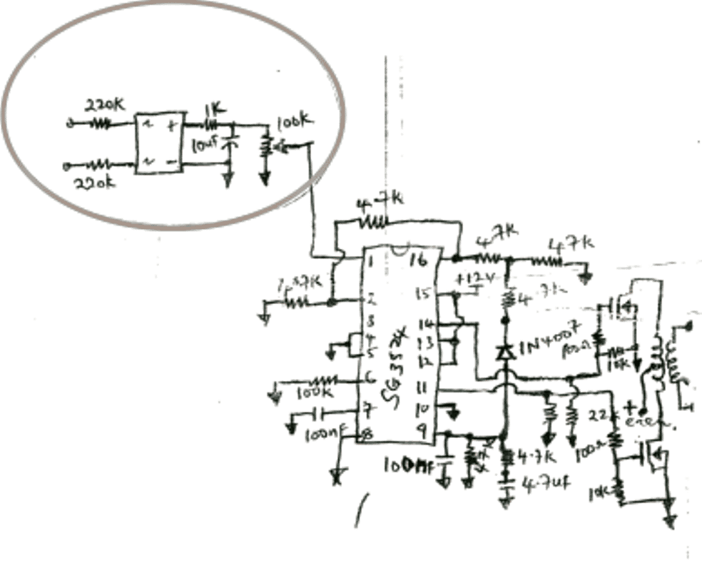
Sir, I would need your help on a project about a schematic that I do not understand a particular section. Our Lecturer gave us the schematic on a printed sheet to build the circuit on our own. He listed the parts but building the circuit is not easy for me as there is one section I do not really understand what that IC represents. Can you help me please The section I circled with a pen is the part of the circuit I do not really understand anything about it. The drawing of the circuit was turned upside down by the computer operators I gave it to. Thanks so much for your upcoming review.

Please use this online calculator to calculate the SG3525 parameters.
Solving the Circuit Problem

The section that's circled is a simple bridge rectifier with a potential divider stage in the form of a 100k pot. It rectifies and sends a sample feedback voltage from the inverter mains output to pin1 of the IC which identifies this feedback and accordingly controls the PWM of the IC and regulates it so that the output from the inverter never exceeds a predetermined limit as set by the 100k preset.

pin1 is the sensing input of the IC which responds and makes the PWMs narrower whenever the fed voltage from the 100k pot exceeds a certain predetermined limit.

Pin1 of IC SG3525/3524 actually forms one of the pinouts of the internal error amplifier opamp. The term error amplifier itself suggests that the opamp is assigned to sense and check a feedback sample voltage (error signal) from the inverter output and correct the output PWM width accordingly. This voltage is sensed with reference to the other pin of the IC (pin16) which is internally fixed at a reference voltage of 5.1V.

In case a rising feedback is detected, the potential at pin1 of the IC which is the sensing input of the error amplifier proportionately goes higher than the other complementing pin16 of the opamp creating a high at the output of the internal error opamp.

This high is utilized internally to modify or slim down the PWM frequency which in turn forces the mosfets to conduct with proportionately lower current, thus correcting the output voltage of the inverter automatically with respect to the feedback signal.

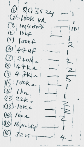
Parts list for the above shown SG 3525 inverter circuit with auto PWM voltage control feature
You'll also like:

  • LM324 voltage regulator circuitAdjustable Voltage Regulator Circuit using LM324 IC with Over Current Protection
  • surgeSurge Arrestor Circuit with Measuring Facility
  • pwmPWM Controlled Voltage Stabilizer Circuit
  • upgrade inverter power by adding mosfets in parallelParallel MOSFET Calculator Tool: How to Connect MOSFETs in Parallel Safely

Filed Under: Voltage Control and Protection Tagged With: 3525, Automatic, PWM, Regulation, SG, Voltage

About Swagatam

I am an electronics engineer and doing practical hands-on work from more than 15 years now. Building real circuits, testing them and also making PCB layouts by myself. I really love doing all these things like inventing something new, designing electronics and also helping other people like hobby guys who want to make their own cool circuits at home.

And that is the main reason why I started this website homemade-circuits.com, to share different types of circuit ideas..

If you are having any kind of doubt or question related to circuits then just write down your question in the comment box below, I am like always checking, so I guarantee I will reply you for sure!

Previous Post: « Make this Car Interior Light Fader Circuit
Next Post: Make this LED Cricket Stump Circuit at home »

Reader Interactions

Questions & Answers

Total Posts: 16
Newest Oldest
Johan
August 17, 2026 • 2 months ago #212118

Then how do you install it on the IC, sir? Can you give a picture example? https://www.homemade-circuits.com/wp-content/uploads/2026/06/add-voltage-regulation-output-via-optocoupler-and-TL431-feedback-e1782724372274.jpg

Reply
SwagatamAdmin
August 17, 2026 • 2 months ago #212122

You just have to follow the instructions as given in the diagram…just connect those points as given in the diagram…the 220V comes from your inverter output…

Reply
Johan
August 16, 2026 • 2 months ago #212097

Hi sir, is this correct? https://drive.google.com/file/d/15r7lNVSz-4ODN_mK6Sv6pRNwnNtSaVJO/view?usp=drivesdk

Reply
SwagatamAdmin
August 17, 2026 • 2 months ago #212115

Hi Johan, it looks correct to me, but please refer to the following design to be perfectly sure:
https://www.homemade-circuits.com/wp-content/uploads/2026/06/add-voltage-regulation-output-via-optocoupler-and-TL431-feedback-e1782724372274.jpg

Reply
Patrick
April 5, 2022 • 5 years ago #117970

Sir
please explain beter your answer to chidubem.So if i need a 1000w inverter with a irf150N, the number of mosfet in parallel will be 1000 divided by 42A.,which is around 23 mosfets , its much.

Reply
SwagatamAdmin
April 5, 2022 • 5 years ago #117985

That is correct. If you want to reduce the number of mosfets then use something like IRF3205

Reply
Robert
April 16, 2018 • 8 years ago #59821

Thanks once again for your help . The charger circuit you referred me to is a 48v charger with 56v input. Please how can I modify it to give me 24v at 30amp

Reply
SwagatamAdmin
April 16, 2018 • 8 years ago #59824

The same circuit can be used for charging a 24V battery also, make sure to use 28V as the input

Reply
mattlander clairzil
January 14, 2017 • 10 years ago #48072

Sir please you can retry to make the diagram of this circuit ? I see anything in this circuit…

Reply
SwagatamAdmin
January 15, 2017 • 10 years ago #48098

Matt, I have enlarged the diagram please check it out…..

Reply
Chidubem Paul
October 3, 2016 • 10 years ago #45228

Sir
please can explain to me how to choose a MOSFET for an inverter
for example choosing IRF540 for 1000W inverter how will I know the number of this MOSFET I will connect in parallel to govet me 1000w at the transformer output

Reply
SwagatamAdmin
October 4, 2016 • 10 years ago #45242

Chiduben, first find the maximum current handling capacity of the mosfet…then divide 1000 by this value. This will provide the number of mosfets that needs to be connected in parallel…

keep a 20% +/- margin for safety

Reply
Atinuke Funke
January 20, 2016 • 11 years ago #37869

Well done Swagatam,how can i calculate the efficiency of a built inverter and its power rating especially transformer based ones. i have several formulas but how to get the Pin and Pout is the issue.

Reply
SwagatamAdmin
January 21, 2016 • 11 years ago #37893

thanks atinuke, the easiest way is by practically connecting a known load at the inverter output, then by measuring the current through the load and through the battery separately.

after that the battery side current could be multiplied by the battery voltage to get the input wattage.

and similarly the output side current could be multiplied with the output voltage for verifying the output wattage.

finally dividing the output result with input result and multiplying by 100 would fetch you the efficiency of the inverter with the given load.

Reply
KAKOOZA JOSEPH
October 13, 2015 • 11 years ago #34794

Hi sir, help & design for me an inverter driver circuit using a multivibrator system of two transistors
Then design for me the suitable power stage to be used, thanks.

Reply
SwagatamAdmin
October 14, 2015 • 11 years ago #34810

Hi Kakooza, you may refer to the following posts:

https://www.homemade-circuits.com/2012/07/simplest-and-best-100-watt-inverter.html

https://www.homemade-circuits.com/2012/02/how-to-make-simple-200-va-homemade.html

Reply

Need Help? Please Leave a Comment! We value your input—Kindly keep it relevant to the above topic! Cancel reply

Your email address will not be published. Required fields are marked *

Primary Sidebar

My YouTube Channel

Circuit Simulator: Draw and Simulate Schematics

circuit simulator image

Categories

  • Arduino Projects (95)
  • Audio and Amplifier Projects (134)
  • Automation Projects (18)
  • Automobile Electronics (104)
  • Battery Charger Circuits (90)
  • Datasheets and Components (109)
  • Electronics Theory (151)
  • Energy from Magnets and Earth (43)
  • Games and Sports Projects (11)
  • Grid and 3-Phase (20)
  • Health related Projects (27)
  • Home Electrical Circuits (13)
  • Indicator Circuits (16)
  • Inverter Circuits (98)
  • Lamps and Lights (161)
  • Meters and Testers (72)
  • Mini Projects (28)
  • Motor Controller (68)
  • Oscillator Circuits (30)
  • Pets and Pests (15)
  • Power Supply Circuits (91)
  • Remote Control Circuits (50)
  • Security and Alarm (65)
  • Sensors and Detectors (107)
  • SMPS and Converters (46)
  • Solar Controller Circuits (62)
  • Temperature Controllers (44)
  • Timer and Delay Relay (51)
  • Voltage Control and Protection (44)
  • Water Controller (37)
  • Wireless Circuits (31)

Subscribe to get New Circuits in your Email

Other Links

  • Privacy Policy
  • Cookie Policy
  • Disclaimer
  • Copyright
  • Videos
  • Sitemap

People also Search

555 Circuits | 741 Circuits | LM324 Circuits | LM338 Circuits | 4017 Circuits | Ultrasonic Projects | SMPS Projects | Christmas Projects | MOSFETs | Radio Circuits | Laser Circuits | PIR Projects |

Recent Comments

  • Swagatam on Inverter Circuit with Feedback Control
  • Swagatam on How to Make Step Down Transformers
  • Jerry Adeosun on Inverter Circuit with Feedback Control
  • Pedro Lima on How to Make Step Down Transformers
  • Martins Vita on Understanding IC 4043B, IC 4044B CMOS Quad 3-State R/S Latch – Working and Pinouts

Social Profiles

  • Twitter
  • YouTube
  • Instagram
  • Pinterest
  • My Facebook-Page
  • Stack Exchange
  • Linkedin

Calculators

  • ZVS Induction Heater + Tank Calculator Tool
  • Zener Diode Calculator
  • Wire Current and Thickness Calculator (Ampacity Calculator)
  • Voltage Divider Calculator
  • Transistor Base Resistor Calculator
  • Transistor Astable Multivibrator Calculator
  • TL431 Calculator
  • Solar Panel, Inverter, Battery Calculator
  • Ferrite Core Air Gap Calculator Tool
  • Parallel MOSFET Calculator Tool: How to Connect MOSFETs in Parallel Safely
  • LC Resonance Calculator for EV Battery Charger Circuits
  • LED String Series Resistor Calculator
  • PFC (Power Factor Correction) Calculator Tool: 3kW
  • Passive Power Factor Correction (PFC) Calculator
  • LM567 IC Calculator Tool
  • SMPS Flyback Boost Converter Calculator
  • Shunt Resistor Calculator for Ammeters
  • SCR and Triac Gate Resistor Calculator
  • Battery Back up Time Calculator
  • Boost Converter Calculator (Non-Isolated)
  • Bootstrap Capacitor Calculator
  • Buck Converter Calculator
  • Buck-Boost Converter Calculator
  • Capacitance Reactance Calculator
  • DCM Flyback Transformer & Wire Gauge Wire Size Calculator Tool
  • Filter Capacitor Calculator
  • IC 4047 Calculator (Frequency and PWM)
  • IC 4060 Calculator
  • IC 555 Astable Calculator
  • IC 555 Monostable Calculator
  • IC SG3525, SG3524 Calculator
  • Inductance Calculator
  • Induction Heater Inductor and Resonant Frequency Calculator
  • Induction Heater Work Coil Calculator
  • Inverter LC Filter Calculator
  • LC Resonance Calculator
  • LED Current Calculator
  • LM317, LM338, LM396 Calculator
  • NAND/NOT Gate RC Values Calculator
  • NOT, NAND Gate Frequency Calculator
  • Notch Filter Calculator Tool
  • Ohm’s Law Calculator
  • Phase Angle Phase Shift Calculator
  • Power Factor (PF) Calculator
  • RC Filter Calculator
  • Reactance Calculator
  • Sine Table Calculator for SPWM Arduino Code
  • Small Signal Transistor(BJT) and Diode Quick Datasheet
  • SMPS Calculator for Toroidal Ferrite Transformers
  • SMPS Flyback Transformer Calculator – Design by Target Duty Cycle
  • TL431 Calculator
  • Op-Amp Hysteresis Resistor Calculator

© 2026 · Swagatam Innovations