In this post I have explained about a simple surge voltage protector circuit using a fuse and a triac crowbar circuit and also learn the method to record and measure the last maximum surge that could have destroyed the specified load in case the protection was not introduced. The idea was requested by Mr. Akram.
Circuit Objectives and Requirements
- I am akram, a university student from sri lanka.. first i would like to thank you for the excellent work of publishing articles and helping out students.
- I need to develop a surge arrestor monitoring device which measure surge currents and when it about to reach its maximum capacity, the device should give signal to remote pc. Basically a surge counter.
- Help me with this project sir
Surge Arrestor using a Fuse and a Triac Crowbar Circuit
An ordinary level of surge can be arrested and stopped using the conventional methods such as through MOVs, or NTCs, but a high voltage surge prevention could require costly devices or complex circuitry, therefore instead of employing such a surge controller it's better to use a method that would completely kill the surge and the associated dangers by blowing of a fuse.
Circuit Diagram
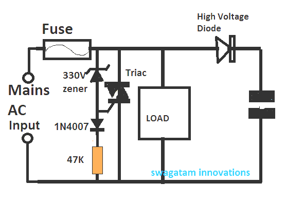
Referring to the above simple surge protection circuit, the triac along with the zener diode and the 47K resistor forms a simple crowbar circuit stage.
The value of the zener diode decides at what input surge level the triacs needs to fire.
Here it is shown as 330V which means, in this design the triac is supposed to fire and conduct when the input mains level exceeds the 330V limit, other values can be selected for other surge levels as preferred by the user.
In a situation where the selected zener limit is exceeded by the input mains, the triac is instantly triggered causing an instant short circuit across the mains line by the triac, which causes the fuse to blow of.
The above procedure makes sure that whenever a high voltage surge appears within the mains line, the fuse is blown of in order to prevent the surge from reaching the load and damaging it.
This takes care of the surge aresstor or controller design, now I have explained how this surge level may be recorded for knowing the exact measure of this surge.
Measuring and Monitoring Surge Voltage
In the diagram above we are able to visualize a diode and a capacitor connected at the extreme right side for the design.
The diode is positioned to rectify the surge AC, and this rectified AC peak surge level entering the capacitor is stored inside it permanently, until it is discharged manually by some means.
This stored surge value can be measured by reading it on any standard digital multimeter.
Once the surge is recorded, the fuse can be replaced back for the the next subsequent surge in rush and for storing the data inside the capacitor.
The diode and the capacitor must be rated as per the predicted maximum surge voltage, in order to make sure that it does not burn or get damaged in the process.

Questions & Answers
Hi sir….i want to design a circuit that detects the sudden rise in voltage peak of decreasing voltage signal and lights up an LED as indication. Please share the circuit diagram for this circuit.
Hi Joe,
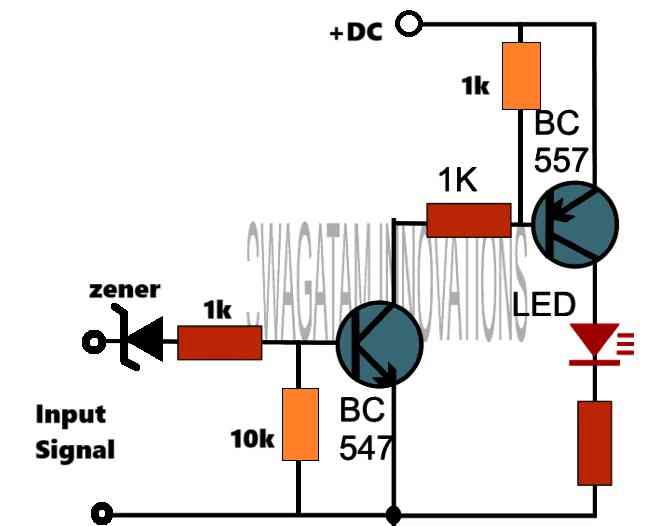
You can try the following concept:
The zener value will depend on the peak level.
Sir im not getting the right output, the LED is not glowing when the peak is reached, connection are all right, is there any other approach to the statement
Joe, the circuit will work only if the peak exceeds the zener diode value.
Can you please tell me what is the peak level range of your input signal.
Since the triac is causing a short across the mains, theoretically infinite current only limited by the internal resistance of the triac will flow till the fuse is blown. What’s the I2T capacity of the triac and what the total I2T fuse will let through before it fuses will determine if the triac will also survive. HOPEFULLY, THIS WILL NOT TAKE YOUR HOME OR LAB WIRING WITH IT.
Hi. How do you choose the value of the fuse?
It will depend on the load current.
Thank you for reply. I want to use this as a protector inside a power strip. So the number of devices attached to this strip may vary at a given time. Would it then be unwise to use it here?
Yes, the fuse cannot be selected if the load is of varying nature. In fact this circuit is only recommended for testing and monitoring purpose, it is not recommended to be used in power strips. For power strips you can try one of the following designs:
https://www.homemade-circuits.com/how-to-make-simple-ac-mains-surge/
Please sir, I want to ask is there no other thing that can be used in place of the 330v zener because in my area such high voltage zener are not sold. The highest here is 150v zener. Can I connect two 150volts zener in series to get 300v zener that I can use or can connect two diodes together to form a zener like network. If not what best do I do because I need to build the circuit.
Hi Moses, yes you can put two 150V zeners in series to create an equivalent 300 V zener diode.
Ok Sir I will do that. God bless you
Hi Swagatam I don’t see how the zener will not short out the mains when the voltage reverses polarity every half cycle. It only takes a fraction of a volt to fully conduct when forward biased. Then the volt drop across R should also be enough to turn on the triac. regards Patrick
Hi Patrick, you are correct, the triac will conduct for the opposite AC cycles also….However I have corrected the circuit now by putting a reverse diode in series with the 47 K resistor, you can check it out
Well done Swag, please what value of triac ampere will be useful for surge
It will depend on the load wattage, it should be greater than the maximum load current spec.
swag , by noise i meant any unwanted voltage transient imposed on the line when a heavy inductive load is present on the line!!!
a o.1uF ceramic cap ,400Vdc should be good!!! thanks!!!
OK thanks, yes any capacitor in the range of 0.1 to 0.47uF should do the job?
hi , how about triac misfiring due to noise? every time, fuse has to be replaced….
hi, how can noise misfire a triac?, triac will require a substantial amount of power, around 12V and 20mA to trigger ON through the zener. yet still a small capacitor can be added across its gate/cathode to make it absolutely foolproof.
Hello sir, Good day to you
Can you help me How to Select the Right TVS Diode For our circuit Application ? protection in the circuit
Hi Satheesh, tvs diodes are quite like MOVs, they are selected as per their max voltage clamping rating…for a 220V application you can select a 1amp/330V rated TVS diode.