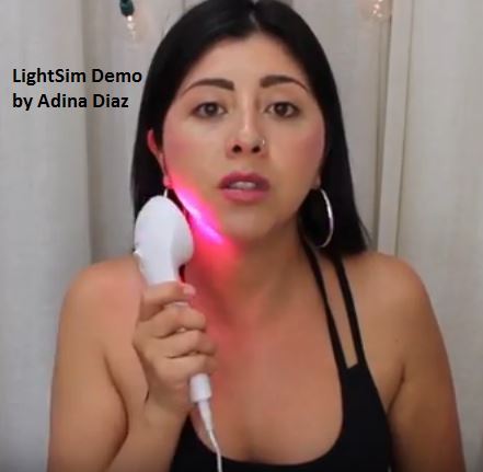
An LED based LightStim is a device used for rejuvenating facial skin by stimulating cell growth. Normally, RED LED is used in these devices since red light have been found to be working the best for improving skin health, by eliminating facial wrinkles. Blue LED light have proved more effective against harmful bacteria responsible for face acnes and other forms of skin damage.
In this post I have explained how to make one such LED lightsim circuit using ordinary and cheap ingredients like a few red LEDs, and a mobile phone charger.
Overview
According to the researches, red light wavelength which is near to the infrared wavelength works positively to repair skin damage and eliminate wrinkles within a few months of regular therapy.
In the market you will find plenty of these units available, which are publicized to produce magical effects, by rejuvenating your facial skin conditions, especially in people above 40.
At first it may sound like a business snake-oil publicity, however the truth is that, this technique is actually FDA approved (according to the sources).
Therefore, it is a proven fact that RED LED lights indeed work for enhancing skin health. Furthermore, since there are no side effects against LED light application, it's worth giving a try..
How it Works
Red LED light being near to the infrared wavelength works by penetrating deep inside the skin surface and stimulate skin cells to produce collagen. This in turn helps the skin to become supple, softer and wrinkle free.
Infrared LEDs can be also used, but being more expensive, red leds are preferred, which provide almost the same results as the IR LEDs.
Some ready made devices have a mixture of red and blue LEDs, for generating a two way effect of eliminating wrinkles and also killing harmful bacteria and acnes.
How RED Light is Beneficial for Skin Repair
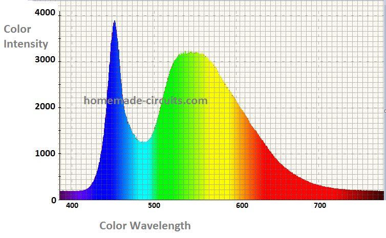
The wavelength of RED light spectrum lies between 600 and 800 nm, and is found to be helpful for straightening facial wrinkles. Lights of this wavelength and higher have the ability to penetrate around 5mm under the skin to influence the cells.
As per the studies red light therapy works by inducing a biochemical process within the skin cells, boosting mitochondria activity. Mitochondria are the active organelles that energize our body cell by producing adenosine triphosphate (ATP), the essential energy molecule consumed by the cells.
Due to the influence of Red light, mitochodria in our skin cells get stimulated and they begin producing higher amounts of ATP, which helps our skin to appear more lively and tighter. The process also helps faster skin repair and removal of fine facial wrinkles.
Does Red Light Therapy Really Work?
Experiments have revealed substantial evidences regarding effectiveness of red light in improving facial skin radiance. However, this may not be possible without other supporting factors like a good planned diet, exercise and a stress free life.
Based on a clinical study conducted on 40 candidates, red led light therapy tried on periorbital wrinkle area helped to reduce the effect by at least 20%.
The analysis of the wrinkle reduction was done using the Fitzpatrick Wrinkle Scale (FWS) across a scale of 1 through 9. Initially, prior to the treatment the average wrinkle on the face of the participants was recorded at around 5.9 in the scale.
After 8 weeks of red light therapy, the wrinkles appeared to minimize to a scale of around 4.5 for the under-eyes region, and approximately 4.0 for the entire face, overall.
How to Make a Red LED LightStim Circuit
Since the specifications of the red LED is not critical for getting the intended effects, making a red lightstim actually becomes very easy.
Any standard red LED having a minimum brightness figure of 65mW/cm2, and wavelength between 600 and 800 nm can be ideally used for this application.
For the power supply a standard mobile changer handset or computer USB can be used.
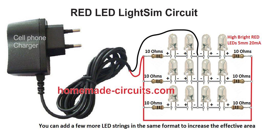
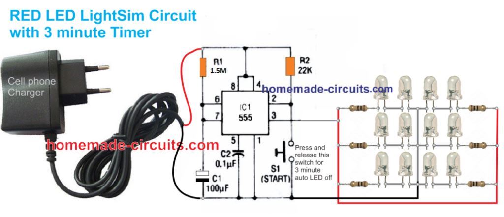
LightSim LED Circuit Diagram
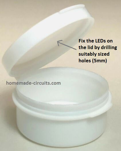
LightSim Enclosure
The LEDs shown in the above image can be fixed (installed) on the lid of any suitable plastic box (like a cosmetic jar) as shown below, by drilling appropriately dimensioned holes on the lid. The hole diameter must be such that the LEDs fit tightly when pushed through. A notch could be cut at the edge of the LED to allow the supply chord out from the enclosure.
You may use a mixture of red and blue LEDs alternately for the LEDs strings to get a dual skin repair feature. The blue LEDs will help killing harmful acne bacteria, while the red LEDs will iron out the wrinkles.
How to Use it
After assembling and installing the LEDs in the enclosure, it's to test it and learn the correct method of using the proposed LED lightSim circuit.
The first step would be obviously to plugin the mobile charger into the mains socket.
This will instantly illuminate the LEDs. Now, for getting the intended effects, you simply have to take the illuminated LEDs very near to your face and apply the light therapy on different selected areas of the face. Make sure to keep the application for at least 3 minutes on selected areas, to obtain optimal performance from the procedure.
It might take up to 8 weeks for any noticeable difference or improvements.
Adding a 3 minute Timer
The above design does not have any automatic 3 minute timer. No problems we can easily include one using a IC 555 based monostable, as shown below:
That concludes our tutorial for a homemade yet effective LED lightsim circuit for an non-evasive skin repair therapy.
Warning: Although the theory explained above is technically correct and is created after a thorough research on the field, the author takes no responsibilities for the consequences whatsoever, from this design. Users are advised to exercise discretion.
Additionally, the LEDs used in the circuit are too bright and may be harmful for the eyes. Therefore, users must avoid looking directly into the LEDs from top, and not use the therapy directly on eyes, or exercise appropriate protections while implementing the actions.


Questions & Answers
Can you please tell me what is the power of the Red LED you mentioned?
I tried to use Tinkercad using the values you mentioned, seems the resistor is 10 Ohm quite low so I have to change it to 330 Ohm, I think because I used a 9-volt battery.
Thanks,
Far K
The forward voltage of the LEDs is 3.3 V and the current is 20 mA, so the power = 3.3 x 0.02 = 0.066 watts
The formula for calculating the limiting resistor is:
R = (Supply DC – Total FWD drop of the LED series) / LED Current
Hello Mr. swagatam I am working on a hand held portable PC. The power adapter supplies 19V 10A to the system. I am working on a power supply that can supply 19V 7A to a Pico PSU and charges a 14V battery at the same time. If the battery is being charged the pico psu takes power from the adapter if not the pico psu takes the power from the battery.
I cant find a way to able to charge my battery and use the portable pc at the same time without the pc shutting down.
Hello Emmanuel, I think you may find the solution through one of the concepts posted under this article
https://www.homemade-circuits.com/simple-dc-ups-circuit-for-modemrouter/
Hi, thanks, glad you liked my work. In your case the only way to control current is by adding a calculated inductor in series with the AC line. I cannot remember any other option for controlling current to an inuctive load such as a refrigerator.
Would you pleass check out this video, minute 1:40? how is this machine increasing pedal force thus increasing power? how can you play with a generator like that? you think its a self excited generator with variable excitation field? if you know about generators. thanks
I saw the video! The basic working principle of any alternator is, if the RPM increases the output voltage increases. So according to me increasing pedaling increases the RMS voltage of the generator. And increase in the RMS voltage also increases the average current, and thus the wattage. However, to transform this increase in voltage to an increased current, we will need an appropriate transformer.
Thanks again for the reply. What I do not understand is the following: You pedal with same constant speed but using the button, you can change the force and create more power for same speed. Normally a generator spinning torque depends on its consumers. If you tie a 10W consumer it will spin easily, if you add another 100w consumer it will be harder to spin. How is the button doing this? ???????? If you remove all consumers, it will be very easy to spin and will produce a voltage but the current will be zero. as soon as current starts to flow through its consumers, the pedal force increases. I was thinking maybe the button controls the current somehow, but how can you variably limit amperage in a circuit?
thanks !
Hello,
So, im starting to understand but what i do not know is what exactly does that button do? how is it controlling the load? this is where im stuck at. When its tied to the grid, to the wall socket, the load is max? and then how does the button split/lower the load?
Sorry to bother you, im an automotive engineer and im lacking the electric part.
This can be complex. The 220V alternator AC is first converted to a 310V DC, which is then applied to a transformerless inverter. This inverter converts the voltage back through 220V AC through sine PWM, for the grid. This inverter may include a current control stage which could be controlled by the switch on the machine.
Please note that I would be deleting all these comments because it is posted under an unrelated article.
For further discussion you can post your comments under thus link:
https://www.homemade-circuits.com/generate-electricity-from-your-gym/
The button keeps adding more and more load with the generator. The more it connects the harder it gets to pedal. Button is only connecting more load with the generator output it is not controlling the current. When more watts are shown on the meter means more power is being required to pedal.