In this article I have explained how to build an electronic acupuncture circuit, also called bio-stimulation circuit., and use it for a possible treatment of many common body ailments, without any side-effects.
The unit, if built and implemented correctly can possibly provide impressive results in healing issues related to headaches, body pain, muscle pain, fatigue, hypertension, anxiety, depression etc.
The good thing about an electronic acupuncture system is that, unlike real acupuncture it does not depend on invasive method of piercing the skin with needles, rather works by applying sharp electrical pulses on the surface of the skin, for achieving identical beneficial results.
WARNING: Please be sure to read this warning message before you build and use this project: Wrong use of the Bio-Stimulator or the electroacupuncture could be dangerous. Never utilize the unit on the eyes or on open sores and wounds, or in case you have a pacemaker installed in your body, or people who are presently undergoing treatment for cardiovascular disease or arrhythmia, or females who are pregnant. Even for people who are in good health condition, they must seek advice from a qualified doctor before implementing this device practically. The author of this article cannot be held responsible for any mishap or damage arising from inappropriate use of this device, please try it at your own risk and discretion.
History of Acupuncture
According to the Tabers Encyclopedic Medical Dictionary, the acupuncture procedure may be defined as "the puncture with needles for diagnostic and therapeutic counter irritation purposes." Let's briefly try to understand how the subject of acupuncture came to existence.
Hundreds of years prior to the Western world started to fully grasp the circulation of blood and the nervous system, the early Chinese formulated the concept that a system of energy circulation exists within the body of a human. The Chinese reported that crucial energy for life runs via a chain of routes, or meridians, TWELVE of which can be found in either side of the body.
These meridians were believed to travel through the deep tissues of the body, appearing from time to time. Each one of the locations where the meridians contact the surface were thought to be beneficial therapy areas for illnesses to one or more organs.
It had been believed that piercing needles on these surface points could possibly cure complications with a person's heart, gallbladder, liver, lungs, colon or other organs.
Western curiosity in the theory (sooner or later named "acupuncture") could not become popular before the 1970s, when physicians from the People's Republic of China showed that the technique enables you to control surgical discomfort.
Following 20 minutes of stimulation, a person receiving successful acupuncture therapy could be perfectly conscious, alert, and mindful of all executed surgical processes, however, without feeling any sort of pain.
The genuine things through which individuals get the ability to endure surgery throughout acupuncture stimulation are still mysterious.
A few researchers guess that during acupuncture bigger sensory fibers are turned on, which help suppressing the exchange of impulses through the tiny fibers, responsible for transporting the sensory input of pain.
Other experts assume that naturally triggered, morphine like ingredients (for example endorphins) could possibly be produced inside the brain due to the stimulation effect. As soon as these forms of ingredients bind to sedate the receptor cells, a pain prohibition strategy is turned on.
Patients struggling with soreness in the back, head, stomach, or other places might feel temporary alleviation through this type of pain suppressing approach. Even though extensively recognized over the Asia as a reliable practice, acupuncture is considered rather differently in the Western world.
The leading important factor could be the American Medical Association (AMA), that doesn't acknowledge acupuncture as a genuine medical technique to heal the unwell.
Not having the AMA's approval, acupuncture ended up being for many years viewed as by many as a kind of "black magic." That isn't shocking taking into account the number of people find the notion of inserting needles to their skin repugnant.
Furthermore, there exists a significant level of risk when the method is conducted through an unlicensed doctor. A single wrongly inserted needle could possibly do significant harm in case an important organ or artery is punctured.
The concern of a possible harm from metal needle encouraged the advancement of electronic acupuncture. This more recent approach employs electronic pulses instead of needles to regulate pain, develop and reinforce muscles, improve blood flow, and launch the human body's unique natural pain and inflammation relievers.
Even though still not totally accepted by the AMA, electronic acupuncture has just lately acquired endorsement among chiropractic professionals and a modest proportion of medical professionals as an alternative strategy to their therapeutic techniques; they think electronically stimulated acupuncture to be safer and a method that operates effectively for specific body ailments.
You may also want to read about Transcutaneous Nerve Stimulator Circuit
Circuit Description
The circuit diagram for the Bio-Stimulator or the electronic acupuncture can be witnessed in the below shown image. The circuit is powered through a 9 V battery, B1. Switch S1 is utilized to switch the device on / off, and the resistor R1 is positioned like a current limiter for the circuit.
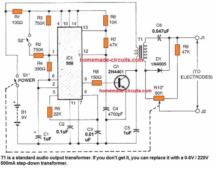
Resistors R2-R4 and capacitor C1 are configured like a timing circuit together with IC1, which is a 556 dual timer IC. As long as S2 remains in the open condition, the C1's charge/discharge period is fixed at somewhere around 2 Hz. When S2 is switched ON, it boosts the charge/discharge period of C1 to roughly around 4 Hz.
The output pin#5 of the IC1 is connected through R5 and C3 with pin#8 of IC1. The area of IC1 consisting of the parts R7, R8, and C4 build the second timing circuit.
The function of the first timer is to produce the delay time in Hz, while the 2nd timer generates the required precision pulses for the inductor. The pulses for the inductor is delivered to the base of Q1 transistor by means of a current limiting resistor R8.
During the period transistor Q1 switches ON, the primary winding of the audio-transformer T1 gets grounded briefly, which cause T1 to energize.
Each time T1 is energized and de-energized cause the capacitor C5 to charge and discharge. This repetitive charging cycles decreases the rise and fall time of the pulse, which subsequently enhances the time-span of the output pulse through T1, and simultaneously carve the output waveform edges to appear more like a half sinewave. Parts C5, D1, and R9 are further used for shaping the output waveform of the circuit.
Potentiometer R10 is employed to regulate the pulse amplitude up to as high as 200 V along with an interval of 2 ms, which may have an total current drain of below 10 mA.
Parts List for the Electroacupuncture
| Category | Component | Value/Specification |
|---|---|---|
| Semiconductors | IC1 | 556 dual timer, integrated circuit |
| Q1 | 2N4401 NPN transistor | |
| D1 | 1N4005 silicon rectifier diode | |
| Resistors | R1 | 100 ohm, ¼ watt, 5% |
| R2, R3 | 750,000 ohm, ¼ watt, 5% | |
| R4 | 390 ohm, ¼ watt, 5% | |
| R5 | 22,000 ohm, ¼ watt, 5% | |
| R6 | 10,000 ohm, ¼ watt, 5% | |
| R7, R9 | 47,000 ohm, ¼ watt, 5% | |
| R8 | 150 ohm, ¼ watt, 5% | |
| R10 | 50,000 ohm potentiometer with SPST switch (S1) | |
| Capacitors | C1 | 1 µF, 16 WVDC, electrolytic |
| C2 | 0.1 µF, ceramic-disc | |
| C3 | 0.01 µF, ceramic-disc | |
| C4 | 4700 pF, ceramic-disc | |
| C5 | 1 µF, ceramic-disc | |
| C6 | 0.047 µF, ceramic-disc | |
| Additional Parts | T1 | Audio transformer, 8-ohm primary, 1,200-ohm secondary (Mouser KM003) |
| J1, J2 | Acorn cap nut | |
| S1 | SPST switch (part of R10) | |
| B1 | 9-volt alkaline battery |
Calibration and Use
After connecting a battery, switch on power through R10/ S1; after that start adjusting the pot R10 until the middle of its rotation. Place the probes on the inner side of your arm and toggle S2 to each of its specified positions.
You should be able to experience a increase or reduction of the shock pulse. Little by little rotate R10 clockwise or counterclockwise to sense a growing or falling (respectively) of the shock-pulse energy on your skin.
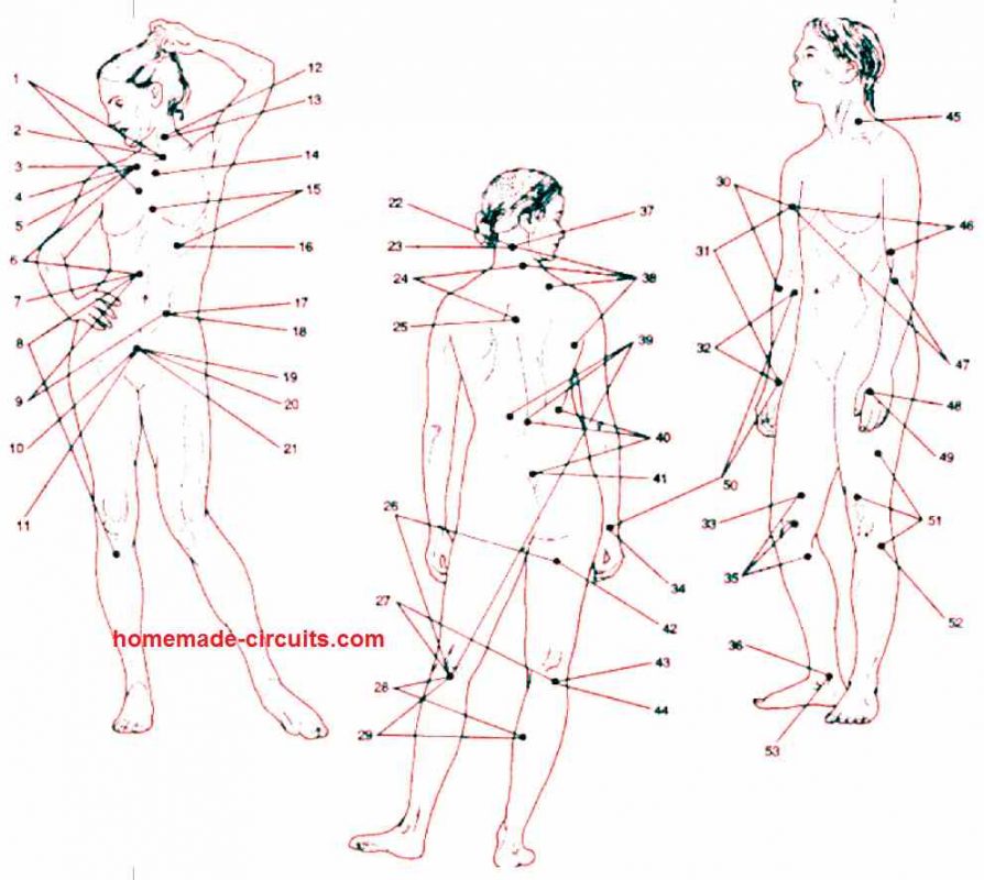
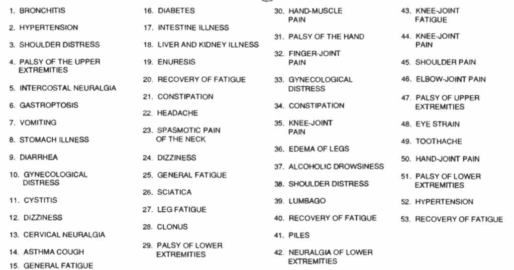
In the following figure you can see a list of health conditions which conventional acupuncture has been believed to treat. In case you are afflicted by one of those troubles, then select the proper acupuncture area and touch the J2 electrode immediately over that spot. The other electrode, J1, could be touched on some other area of the skin. For most effective outcomes, consider implementing the electronic acupuncture circuit approximately 3 times a day for about 5 to 15 minutes. You can stop using the electroacupuncture as soon as you feel a reduction in the pain to your satisfaction.
Electronic Acupuncture Like Stimulator Circuit
The following information has been gathered from medical literature or obtained from healthcare professionals, and then presented in a comprehensible form for everyone. The objective is not to provide you with a treatment protocol to relieve any specific pathology; we do not have the necessary expertise for that. Our aim is simply to introduce you to a facet of medical electronics through a simple realization.
This device is not a gadget and is exclusively intended for personal experimentation. A doctor or physiotherapist will be in a better position to provide you with usage advice to alleviate specific pains or discomfort.
What is Pain
As it is known, A-delta and C fibers enter the spinal cord through the posterior horn. From there, the message travels up to the thalamus and cortex.
It is then interpreted as pain, along with all its consequences (reflexes, memory of the pain, stress, etc.).
What was once a simple nerve signal becomes a sensation of pain, triggering a reaction aimed at diminishing the strength of the original message.
To achieve this, the hypothalamus releases morphinomimetic substances that inhibit this message at its entry point in the posterior horn of the spinal cord.
Although this deviates slightly from our main topic of interest, this bodily reaction also releases other substances that can lead to disorders in the viscera.
These disorders are often referred to as psychosomatic.
Objective of the Stimulator
The function of the stimulator we are proposing is to stimulate the A-delta and C fibers near the pain threshold, in order to induce the production and accumulation of these morphinomimetic substances.
To excite these fibers, low-frequency impulses are needed, with longer duration compared to sensory fibers. Various duration are typically used, ranging from 0.2 ms to 10 ms!
All duration are capable of stimulating the target fibers, with the required current decreasing as the duration increases.
However, a longer duration also results in a more unpleasant sensation.
After experimentation, we have chosen 6 impulses at a frequency of around 800 pulses per second. These values are not critical and can be adjusted.
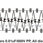
High-Voltage Generator
It is built around a diode pump, which we have described in detail in the previously mentioned article. Therefore, we will not go into it again or the reasons for this choice.
However, you may notice that this time we have three gates in parallel instead of two. This is necessary to deliver the required energy for relatively long pulses.
The astable circuit that provides the driving signal to the diode pump consists of two inverting gates. Its period is determined by R8 and C9.
Timebase
Built around a 555 timer, it delivers calibrated pulses whose duration and frequency are determined by R6, R7, and C10. The output of this 555 timer is also used to drive LED D8 through two inverting gates.
This makes it easy to visualize the proper operation of the timebase.
Output Stage
Capacitor C14 plays a crucial role in obtaining a signal with an average value of zero.
This ensures that the energy balance at the skin level is zero, preventing any electrolysis phenomenon that could result in redness or even burns under the electrodes in extreme cases.
Since this component should not have any leakage current, the use of an electrolytic capacitor is excluded.
Construction
Direct etching appears to be difficult to recommend due to the relatively high circuit density. To eliminate any risk of error, photographic is desirable.
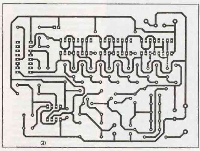
This involves making a photocopy of the circuit on a transparent film and then exposing a photosensitive plate to UV light.
Some advertisers in the magazine are also capable of etching the circuit based on a photocopy of the layout.
On the layout diagram below, you can see that we have provided multiple locations for C14 to facilitate your sourcing.
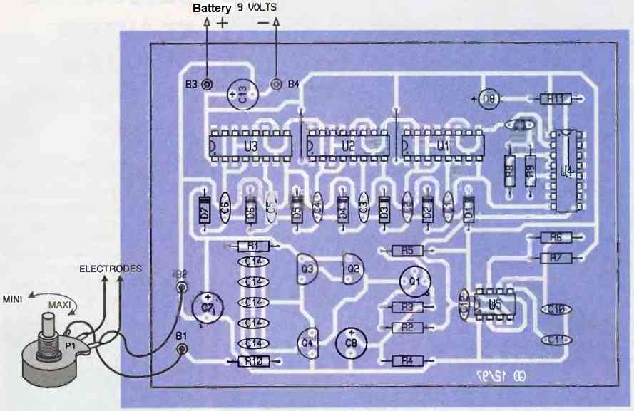
The total value should be around 4 to 5 uF, and you can achieve this with various combinations: one 4.7 uF capacitor, two 2.2 uF capacitors, or five 1 uF capacitors.
In all cases, you should use 63V mylar capacitors. Pay close attention to the orientation of the components, diodes, and electrolytic capacitors.
Using IC sockets will greatly simplify troubleshooting tasks. Beware of potential micro-breaks in the tracks and unexpected solder bridges between component pins!
The transistors used are common types, so do not attempt to replace them with approximate substitutes as it may lead to problems.
For the power supply, you can use a standard switch or, preferably, a switch combined with the current adjustment potentiometer.
This way, when you power on the circuit, the current will be set to its minimum value, eliminating the risk of a mishap.
Testing
The circuit does not include any adjustable components.
Therefore, no fine-tuning is required, and the operation should be immediate if there are no wiring errors.
Upon powering on, you should see the LED blinking rapidly at a frequency of around 6 Hz.
If this is not the case, there is no need to proceed further; you must carefully recheck everything.
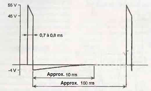
A test can be conducted using a 1000-ohm load resistor to simulate the resistance of the human body between the electrodes.
An oscilloscope is essential for visualizing the voltage across this resistor.
The measured voltage should be in accordance with the figure as shown below, when the potentiometer is in the maximum position.
How to Use
The electrode pads to be used are flexible, with a surface area of about 150 mm2, as shown in the figure below. The simplest way to stimulate is to place the two electrodes on either side of the painful area.
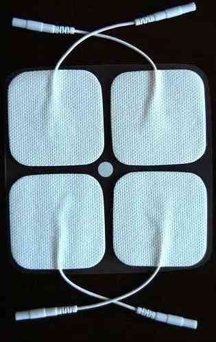
However, this is not necessarily the most effective method. For example, the sciatic nerve extends all the way down to the foot.
To relieve sciatica, it may be more judicious to stimulate a part of the nerve where the pain does not seem to be localized.
There is no universal recipe for the method, and that's where the experience of the physiotherapist or doctor comes in. In particular, remote stimulation can be done through known "trigger points" recognized by practitioners.
These points often correspond to acupuncture points. The results of stimulation may not be as strong as those of acupuncture, but the term "stimulator like acupuncture" is generally used.
Before placing the electrodes, it may be good to degrease the skin with a little alcohol to ensure better contact.
Once they are in place and properly pressed against the skin, carefully check that the potentiometer is in the minimum position.
Then, power on and gradually increase the current setting. You will feel very close pulses. Increase the current to feel a strong sensation.
Beta-endorphins will start to kick in and raise the pain threshold! When the sensation decreases, increase the current again—new beta-endorphins, a new increase in the pain threshold, and so on.
To achieve interesting results, it is necessary to stimulate for at least 10 to 15 minutes.
It is possible to reach a relative insensitivity of the affected area, with a raised pain threshold for several hours.
The paradox of this method is that the more unpleasant the stimulation, the more production of morphine-like substances occurs, resulting in a faster and more lasting effect.
However, this does not mean that you should intentionally cause a lot of pain just to feel better when it stops!
Don't dream, if the pain you want to relieve is really too strong, these electrostimulation methods are a valuable tool among others but are not necessarily the miracle treatment sometimes described.
At the end of the stimulation, do not abruptly cut off the power, but gradually decrease the current. This will prevent an unpleasant shock.
Indications and Contraindications:
As previously mentioned, and since we are not medical professionals, we cannot provide precise information.
This type of device is used daily by doctors and physiotherapists and can yield spectacular results when used correctly, but it may also have no effect. In general, good results are obtained in relieving chronic pain, lower back pain, sports medicine, and so on.
If you believe that this technique could provide relief, it is advisable to consult your doctor beforehand for valuable advice.
Regarding contraindications, it goes without saying that neither individuals with heart conditions or poor health nor pregnant women should undergo this type of stimulation.
It should also be noted that even in a healthy individual, stimulating the cardiac area is dangerous.

Questions & Answers
Is this the same thing as a TENS unit?
(transcutaneous electrical nerve stimulation)
Yes, the concept is the same…
Can use this by acupuncture needles?not by the gel pad
This product will not work to cure anything. Acupuncture has been proven over and over again to be utter nonsense. And nobody has ever been able to prove these claims. If you are going to be touting this nonsense at least you should be able to show some proof that the things you are claiming are at all credible. Just because acupuncture has been used for a long time doesn’t prove that it works. It is at best ever so slightly better than placebo.
Does placebo work?If so,they are useful.Is acupuncture slightly better than a placebo?If yes,then it is useful.You are obviously biased for reasons you did not openly state here.That said,acupuncture has never been ‘proven’ to be ‘utter none sense” as you falsely stated.What is usually stated is that there is insufficient evidence or research carried out to prove one thing or another.If it actually was simply based on the placebo effect,and knowing that effect is not possible with cats,dogs and cattle,how do you explain away the clinically successful use of acupuncture on said animals?But the best way to know if it works or not is to try it yourself when next you get a fever or anything else.I honestly wish more ‘humans’ would display a little more sincerity and honesty when making statements which will affect the lives of many others instead of simply demonstrating their ignorance and bigotry for all to see.
This circuit was a subject I was unfamiliar with, I have never tried, I can not comment.
Afraid of needles? Try electricity instead.