In this post I have explained about a simple mechanism, and a circuit which will enable a patient's IV drip bottle system to sound an alarm whenever it gets almost empty, and needs a replacement.
The warning circuit will help doctors and the concerned employees to concentrate on other important matters while the drip systems are active, since after installing this unit they won't have to frequently check and be bothered about the level of the liquid inside drip bottles attached with the patients.
Set up Configuration
The proposed IV drip bottle empty alert warning indicator is configured using a mechanical spring stage attached with an electronic stage as shown below:
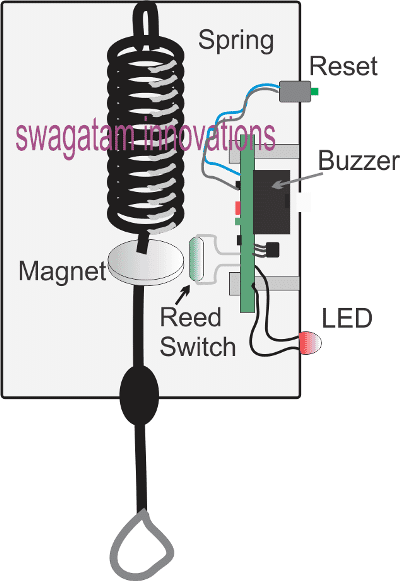
In the figure above we can see the following things:
An appropriately selected spring mechanism attached on the upper surface of a plastic enclosure.
The lower end of the spring is appropriately terminated outside the enclosure with a hook for hanging the drip bottle.
Within the enclosure, the spring end can be seen attached with a permanent magnet, such that under no load the magnet stays in the indicated position, and in the presence of a load which can be a drip bottle filled with the drip liquid, the magnet is displaced to a lower position and away from its original position.
We can also visualize a reed switch positioned near the magnet at its initial no load position.
The reed switch terminals can be seen wired with a circuit assembled over a PCB, and the PCB bolted inside the enclosure as shown in the design.
There are two additional items in the form of a reset push button, a buzzer, and an LED which become the external protruding parts of the PCB.
In the following section I have explained how the above set up works in conjunction with the warning buzzer circuit, inside the enclosure.
How it Works
The working principle of the drip warning indicator is actually very simple:
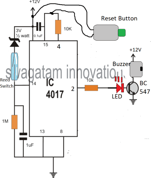
Referring to the image above, initially without a filled drip bottle hung, and the circuit powered ON, the circuit stays inactive, but gets into a standby position.
In this position, the magnet stays near the reed switch in the closed position which causes a positive supply at pin#14 of the IC 4017. However this does not force the IC 4017 to shift its output logic sequence, because simultaneously the supply also resets the pin#15 of the IC through the attached 0.1uF capacitor.
Now, when the drip bottle is attached to the hook, the spring is pulled downward, causing a displacement of the magnet away from the reed switch.
The reed switch instantly opens, removing the positive supply from pin#14 of the IC 4017.
The output of IC 4017 still retains its initial condition, that is the logic stays at the unused pin#3 pinout, due to the negative supply from the 1M resistor.
Let's assume the drip fluid gets used up by the patient, and gradually nears the empty condition.
As soon as this reaches the empty level, the magnet now once again positions itself in its original point where it meets the reed switch.
The reed contacts now closes yet again, causing a positive pulse on pin#14 of IC 4017.
This time the IC reacts to this signal and shifts the high logic from its unused pin#3 to pin#2.
The transistor at pin#2 now activates, and switches ON the buzzer alarm, alerting the concerned member in the vicinity regarding the empty drip bottle. The LED being in series with the transistor base also lights up providing additional warning indication.
The buzzer continues to buzz and is held in the activated position until the concerned member comes and presses the reset button to revert the circuit in its earlier standby position.
In this position the unit allows the replacement of the empty drip bottle with a fresh filled drip bottle, so that the cycle is able to continue yet again as explained in the above paragraphs.
Simple Mechanical Approach
The idea is very simple. The upper enclosure consists of a buzzer, battery assembly with a series reed relay and an ON/OFF switch. The reed relay is positioned at one of the bottom corners of the enclosure.
A spring mechanism is attached at the lower end of the enclosure with a magnet, such that when no drip is hung, the magnet aligns itself at a close proximity to the internal reed relay.
Initially the ON/OFF switch is held in the switched OFF condition, and is switched ON once the drip is hung and the spring is pulled downward moving the magnet away from the reed switch.
Now, as the drip liquid empties its weight decreases and it begins moving upwards due to spring tension, until finally the liquid almost gets over moving the magnet close to the reed. The reed switch now closes switching ON the buzzer.


Questions & Answers
Hello Sir.
I acquired a load cell sensor but I can’t obtain the output. The only way I find is to use an Arduino board.
Hi Jedidiah
I think you can try the instructions provided in the following video, for the all the required details:
https://www.youtube.com/watch?v=sxzoAGf1kOo
Let me know if you any further questions.
You can also investigate using a Force Sensing resistor, which looks cheaper than a load cell:
https://www.homemade-circuits.com/force-sensing-resistor-explained/
Do you have a circuit for this please Sir?
Jedidiah, I have not used a load cell so far, so I am not sure how its output responds to a load.
So I would suggest you to first buy a load cell and check its output response to a varying load, if you provide me with this information then I will be able to design an appropriate circuit as per your requirements.
Hello Sir.
Can this drip monitoring unit be equipped with LCD displays and alarm functionality systems to offer real-time monitoring of drip rates and fluid level to alert clinicians in case of deviations from the prescribed drip rate ensuring timely intervention?
Hi Jedidiah,
That may be possible if a load cell is used for the drip liquid weight detection and interfaced with an LCD.
I think the alarm system will disturb the patient how about finding a way that the alrm will only notify the nurses instead of the patient to hear the noise
The alarm would be in the form of a small beeping buzzer, not a loud alarm. A remote controlled system can make the unit very expensive and complex.
The patient must actually also know that the drip is about to finish.
hi, is please i need help if you can modify the same circuit so that it can alert the nurse when drip is about to finish (Not empty) also automatic stop pumping water/blood to avoid blood to flow back to the drip
Hi, for that you just have to adjust the magnet position appropriately to get the alarm at the desired point
Thank you, but also i need your advice what can i do when the desired point have reached then the drip will automatically stop pumping the water
Sorry could not understand your question, from where will the water come?
yeah from where the water will come, means when the desired point is reached it wi;; sound an alarm then stop water/blood
An electrical valve system will need to be introduced near the opening of the IV package, this valve can be then switched ON/OFF with the help of the above circuit
i am trying to implement the Patient Drip Empty Warning Indicator Circuit but i am having trouble drawing the circuit in the proteus because IC 4017 do not show pin 8 and pin 16. What should i do
I do not use simulators so I can’t suggest about much them…..I would recommend you to build it practically to see it actually working
Hi sir, am using 10k resistor in series with the led, and 9v battery but its just giving beeps but not lighting
Hi kevin, you can try reducing the resistor to 4k7, if still the LED does not light, then your LED may be faulty.
what you did not used the pin 16 for input?
can’t you help me soon? please…clear me 2 things !
is that 4017 circuit is successfully tested?
and confirm me where to give the voltage supplies, please
i’ll be thankful to you.
Give positive to the places where +12V is written, give negative to the points indicated with earthing symbol. Pin16 is on the left side of pin15
Sir.
I tried but it was unsuccessful…
Please send me circuit diagram.
Daniel, “unsuccessful” is impossible. It will work if you do it as shown. Diagram is already given.
Can i use polarized capacitor of 1 uf?
yes that’s fine, please use it also for the pin#15 capacitor, 0.1uF is too small
Can i use 9 volt battery?
And there is not any mention for pin 16 dear.that why em confused.
yes 9V batt can be used, please see my previous comment for pin16 location…
Can
i use 6v zener diodd insread of 3v?
Use a 1N4007 diode. The line side of the diode will go to the reed, other side to positive
Yup okie Sir…
Thank you so much for your help ..
I found out the pin 16 location..actually i was not mention so i got confused..i will try again..hope for good..
Sure! wish you all the best!
Hello Sir, Can You Please Provide Me the More Accurate Circuit Diagram, Its Just Because I am Beginner, And kindly Clear me 1 thing that, Both Negative And positive supply Will be given at @ 2 point? for example negative supply at transistor and at Pin# 13 and 8. right?
Hello Daniel, Yes you are right, I’ll try to update a clearer diagram soon, by the way if you are a beginner then you must go for the second design at the bottom instead.
Thanks for sharing your ideas. I tried building the patient drip warning indicator basing on the circuit you provided above but it has failed to work. Any help?
Thanks in advance
Hi thanks, the concept is so simple and straightforward that it can never fail..please take the assistance of somebody who has good knowledge of electronics and try it again
Oh I forgot to tell you that the circuit finally worked. Thanks for sharing the idea.
I am glad it worked it, thanks for sharing the info.
I am very interested is a IGBT Based, Transformer less AC to AC Stabilizer design.
If you can, please reply.
Ali Baig
CEO
Future Technologies.
+923332109966
SKYPE: ali.baig25
one related design can be found at the end of this post, which you can study
https://www.homemade-circuits.com/smps-mains-voltage-stabilizer-circuit/