So in this article we are trying to make a true MPPT solar charger project using Arduino which will charge a 12V battery from a solar panel and will use MPPT logic to always extract maximum power from the solar panel. That means that even when sunlight changes, we try to adjust PWM duty cycle smartly so that the panel gives out optimum wattage all the time, not wastefully.
What we will need:
We are going to use these things:
- Arduino Nano (or UNO)
- Solar Panel (18V, 50W or similar)
- Buck Converter circuit with N-channel MOSFET and diode
- Current sensor (ACS712 or INA219)
- 16x2 LCD Display
- 10k pot for LCD contrast
- Manual/Auto switch (SPDT)
- Gate driver IC like IR2110 or direct drive for low frequency
- Flyback diode for buck circuit (like 1N5822)
- Capacitors and inductor for LC filter
- 10k resistor for voltage divider (solar V measurement)
- Misc: wires, perfboard, etc.
How it works:
We know that solar panel has one sweet spot where it gives max wattage. That spot changes if sunlight goes up or down. So we need to track that spot using code. That method is called Perturb and Observe (P&O). It means that we change duty cycle slightly and observe if power increased or decreased. If it increased then we go more in that direction. If it reduced then we go back. Very simple.
Manual and Auto switch:
We also want a manual override. That means user can stop MPPT and use fixed duty cycle if needed. So we use a switch connected to digital pin, if it is LOW = auto mode (MPPT running), if HIGH = manual mode (fixed PWM).
LCD display:
We show all info on LCD: solar volts, current, power, PWM duty, mode, etc. So we know what is going on live.
How we sense things:
Solar voltage is read via voltage divider (scaled down to 0-5V)
Current is read either by ACS712 or INA219 (user selects in code)
PWM control:
We use analogWrite (fast PWM pin) to generate switching signal to buck MOSFET. We can also use Timer1 library if more accuracy is needed later.
Basic Tracking Type MPPT Circuit Diagram

Circuit Connections
Solar panel positive goes to input of buck inductor.
Solar panel negative goes to Arduino GND.
Inductor connects to diode (cathode to output).
Output side goes to battery +ve.
Battery -ve goes to common GND.
MOSFET drain to solar panel positive (input), source to inductor input, inductor output to battery +ve.
For calculating the inductor value, you can take the help of this buck converter calculator.
Arduino PWM output (D3) goes to MOSFET gate through 100 ohm.
Pull-down 10k from gate to source.
Flyback diode across inductor input to GND.
Voltage divider: 100k and 10k from panel +ve to A0.
Current sensor:
- For ACS712: Vout to A1, Vcc to 5V, GND to GND.
- For INA219: connect via I2C (SDA, SCL to A4, A5).
- Manual/Auto switch: center to D2, ends to GND and 5V.
- LCD: RS, E, D4D7 to D9D4 (standard wiring).
- LCD contrast pot center to V0, ends to GND and 5V.
LCD Pins and Their Connection Explanation:
| LCD Pin No. | LCD Pin Name | Connects To | Description (crude and simple) |
|---|---|---|---|
| 1 | GND | Arduino GND | This is LCD negative supply. Connect to GND of Arduino. |
| 2 | VCC | Arduino 5V | This is LCD positive. Connect to 5V from Arduino. |
| 3 | V0 | Center of 10k pot | This controls screen contrast. Pot ends go to 5V and GND, center goes here. Adjust for sharp text. |
| 4 | RS | Arduino D7 | Register Select. Tells LCD if we are sending command or data. Connect to D7 of Arduino. |
| 5 | RW | GND | Read/Write pin. Tie to GND for always write mode (we never read from LCD). |
| 6 | EN (E) | Arduino D6 | Enable pin. Triggers the LCD to latch in the data. Connect to D6 of Arduino. |
| 7 to 10 | D0 to D3 | Not Used | These are only used in 8-bit mode. In 4-bit mode, we leave them unconnected. |
| 11 | D4 | Arduino D5 | Data line 4. Connect to D5 of Arduino. |
| 12 | D5 | Arduino D4 | Data line 5. Connect to D4 of Arduino. |
| 13 | D6 | Arduino D3 | Data line 6. Connect to D3 of Arduino. |
| 14 | D7 | Arduino D2 | Data line 7. Connect to D2 of Arduino. |
| 15 | A (LED +) | 220 ohm to 5V | LED backlight +. You can put 220 ohm resistor from here to 5V, or direct 5V if too dim. |
| 16 | K (LED -) | GND | LED backlight -ve. Connect to GND. |
Buck Converter Connection Details
In the MOSFET buck converter stage, we do the connections in the following manner:
We take the solar panel positive, give it to the drain of the MOSFET. Then the source of MOSFET goes to the inductor input. After the inductor we connect to battery +ve. The MOSFET source side also connects with one side of flyback diode and its other side goes to battery -ve. That way when MOSFET turns OFF then diode gives path for inductor to dump energy into battery.
Full Program Code
//==================== MPPT Solar Charger Code by homemade-circuits.com ====================//
//== Dual Current Sensor Options: ACS712 or INA219
//== Manual/Auto Switch Control
//== LCD Display for Parameters

#include <LiquidCrystal.h>
#include <Wire.h>
#include <Adafruit_INA219.h>

//================ LCD Setup ===================//
LiquidCrystal lcd(9, 8, 7, 6, 5, 4);

//================ Constants ===================//
const int pwmPin = 3;           // PWM output to buck converter
const int potPin = A0;          // For manual duty cycle control
const int autoManualSwitch = 2; // Switch for manual/auto
const int voltagePin = A1;      // Panel voltage divider input (0 to 5V)
const int acsPin = A2;          // ACS712 analog output

#define SENSOR_ACS712 0
#define SENSOR_INA219 1
int currentSensorOption = SENSOR_INA219;  // Change to SENSOR_ACS712 if required

//================ INA219 Setup ===================//
Adafruit_INA219 ina219;

//================ Variables ===================//
float panelVoltage = 0;
float panelCurrent = 0;
float panelPower = 0;
float prevPower = 0;
float dutyCycle = 0.5; // Initial duty cycle
float delta = 0.01;     // Step size for perturb & observe

unsigned long lastMPPT = 0;
const unsigned long mpptInterval = 500; // in ms

void setup() {
  pinMode(pwmPin, OUTPUT);
  pinMode(autoManualSwitch, INPUT_PULLUP);
  lcd.begin(16, 2);
  analogWrite(pwmPin, (int)(dutyCycle * 255));

  if (currentSensorOption == SENSOR_INA219) {
    ina219.begin();
  }

  lcd.print("MPPT Solar Ready");
  delay(2000);
  lcd.clear();
}

void loop() {
  bool isManual = digitalRead(autoManualSwitch) == LOW;
  if (isManual) {
    manualControl();
  } else {
    autoMPPT();
  }
  showLCD();
  delay(200);
}

void manualControl() {
  int potValue = analogRead(potPin);
  dutyCycle = map(potValue, 0, 1023, 10, 95) / 100.0;
  analogWrite(pwmPin, dutyCycle * 255);
  readPanelParameters();
}

void autoMPPT() {
  if (millis() - lastMPPT >= mpptInterval) {
    lastMPPT = millis();
    readPanelParameters();

    if (panelPower > prevPower) {
      dutyCycle += delta;
    } else {
      dutyCycle -= delta;
      delta = -delta; // Reverse direction
    }

    if (dutyCycle > 0.95) dutyCycle = 0.95;
    if (dutyCycle < 0.1) dutyCycle = 0.1;

    analogWrite(pwmPin, dutyCycle * 255);
    prevPower = panelPower;
  }
}

void readPanelParameters() {
  panelVoltage = analogRead(voltagePin) * (25.0 / 1023.0); // Assuming 100k:10k divider for 25V max

  if (currentSensorOption == SENSOR_ACS712) {
    int sensorValue = analogRead(acsPin);
    float voltage = sensorValue * (5.0 / 1023.0);
    panelCurrent = (voltage - 2.5) / 0.1; // For ACS712 20A
  } else if (currentSensorOption == SENSOR_INA219) {
    panelCurrent = ina219.getCurrent_mA() / 1000.0; // mA to A
  }

  panelPower = panelVoltage * panelCurrent;
}

void showLCD() {
  lcd.setCursor(0, 0);
  lcd.print("V:"); lcd.print(panelVoltage, 1);
  lcd.print(" I:"); lcd.print(panelCurrent, 1);

  lcd.setCursor(0, 1);
  lcd.print("P:"); lcd.print(panelPower, 1);
  lcd.print(" D:"); lcd.print((int)(dutyCycle * 100));
}
Real MPPT Circuit Diagram with Current Sensor

Step-by-Step Real MPPT Charger Wiring and Connection Explanation:
Basic Arduino Power Setup
- We first give power to Arduino UNO or Nano board. You can use a 12V battery through the Vin pin or just use USB during testing.
- Ground (GND) from Arduino will be the main 0V reference for all modules and parts.
2) LCD 16x2 Wiring (with LiquidCrystal Library)
| LCD Pin | Connect to Arduino |
|---|---|
| VSS | GND |
| VDD | +5V |
| VO | Middle pin of 10k pot for contrast |
| RS | D9 |
| EN | D8 |
| D4 | D7 |
| D5 | D6 |
| D6 | D5 |
| D7 | D4 |
| RW | GND |
| A (LED+) | 220 ohm to +5V |
| K (LED-) | GND |
We use pins D4 to D9 for LCD. A 10k preset is needed between +5V, GND, and LCD pin 3 to adjust contrast.
3) Solar Panel Input to Buck Converter
- Your solar panel (say 18V/5A) will be connected to a buck converter MOSFET stage.
- A powerful N-channel MOSFET like IRF3205 or IRLZ44N is used for switching.
- The PWM pin D3 from Arduino connects to MOSFET gate via 100Ω resistor.
- A fast freewheeling diode (like UF5408 or Schottky) is put across the inductor output.
- You will need an inductor, say 47uH to 100uH and output capacitor (1000uF/35V) to complete the buck stage.
4) Current Sensor Options (ACS712 or INA219)
Option 1: Using ACS712 (e.g., 5A version)
- VCC to +5V
- GND to Arduino GND
- OUT to A0 pin of Arduino
- Insert ACS712 in series with battery negative line, so the load current passes through it.
Option 2: Using INA219
- VIN+ and VIN– are in series with battery positive line
- SDA to A4
- SCL to A5
- VCC to +5V
- GND to GND
In the code, you can switch between ACS712 or INA219 by changing the flag useINA219 = true; or false;.
5) Manual / Auto Switch
- Take a small SPDT or toggle switch.
- Connect one side to GND.
- Center terminal to D10 (this is our mode pin).
- Use INPUT_PULLUP in code so switch LOW means Manual, HIGH means Auto mode.
In manual mode you can manually adjust duty cycle using the pot.
6) Manual Mode Potentiometer (10k)
- Left pin to GND
- Right pin to +5V
- Middle pin to A1
- This pot is used to manually vary the PWM duty in manual mode.
7) Battery Output
- Output of the buck converter goes to the battery terminals
- You can use a 12V lead acid or Li-ion battery.
- Be sure to add a blocking Schottky diode (optional) to prevent backflow.
Table showing the main Arduino Pins:
| Arduino Pin | Function |
|---|---|
| D3 | PWM to MOSFET Gate |
| A0 | ACS712 output |
| A4 | SDA for INA219 |
| A5 | SCL for INA219 |
| A1 | Potentiometer for manual |
| D10 | Manual/Auto switch input |
| D4-D9 | LCD Display |
How It All Works:
- When the sun gets stronger then Arduino increases PWM duty in Auto mode, trying to reach MPP (Maximum Power Point).
- It checks input power = V × I constantly.
- If power increases then it continues adjusting PWM in same direction.
- If power drops then it reverses PWM direction.
- In manual mode, you take control using the pot to tune the PWM duty manually.
- LCD will show voltage, current, power, and duty cycle live.


Questions & Answers
Hi ,Dear
By using N Channel causing very heat up issue rather than using P channel ,
is there is some current leakage exist due to which it become hot
even i used irf1407 even 10 pieces but it become heat up only for 4 Amps
Sure Dear, If you want to use a P-channel MOSFET, then you may have to reverse the PWM action by adding an inverting BC547 transistor between the MOSFET gate and the Arduino output…
Thanks a lot ,
Actually iam using N-Channel Mosfet , even 10 mosfet like irf1407
become heated on only 4 Amps load
i read some where that by using N- channel mosfet in the high side configruation
causing fets heat up issue which is due to the nearlly the
same voltage on both drain and gate here small current flows due to
deference between source and gate that’s why the resistance of mosfet become high
the mosfet become heated, for this it required voltage boost required for this deference between source and gate
is this true ?
Yes, what you have heard is true. I will update the circuit diagram soon with a P channel mosfet
hello swagatam…
pls do you have an article on good explaination on how mppt charge controller works or explanation on how it make vmp and Imp steady and how it keep adjusting duty cycle for perturb and observe?I really want to understand this this and see how I can implement it my self.
Hi David,
I have the following couple of articles which discuss the same concepts which you are interested in, please check them out and let me if this helps or not:
https://www.homemade-circuits.com/real-mppt-solar-charger-circuit-using-arduino-lcd-and-manual-auto-switch/
https://www.homemade-circuits.com/true-mppt-solar-controller-circuit-using-ic-555/
yes this article talks about it but I really don’t understand how the duty cycle changes when doing P&O. does the duty cycle change intensionally to check if power is increased and the continue changing in that direction?
then again let’s say I have a panel of different parameters but same power can it still be used ?
or what if I want to use a high power panel without changing the voltage and current sensor?
In P&O we basically keep pushing the duty cycle a little purposely just to see that if then the panel power goes up or goes down. So now if the power increases then we keep moving in that same direction, but if the power drops then we reverse the step and move the other way. That is why you see the duty cycle changing all the time.
About different panel parameters, as long as the panel can give the same or more watt, then the MPPT will still lock on the peak point automatically, so that is fine. But if the panel watt is very high and you use the same voltage and current sensors, then those sensors must handle that max voltage and current. If they cannot, then you have to upgrade the divider or the sensor rating, otherwise the readings will saturate and the MPPT will not work correctly.
okay,but how do I implement a CCCV alogrithm to it for just one signal pwm if I would be using a synchronous buck converter method,like since mppt changes the duty cycle often, won’t they be an error if adjusting the duty cycle for cv mode and cc mode
Yes, in that case I think it is better to control the CC, CV actions through external analogue cut-off circuits, what do you think?
i think of using a two stage buck converter..lol
The two-stage idea looks valid and simple from a control perspective but you can avoid extra hardware by letting the MCU run MPPT while a faster CC/CV inner loop (software or hardware) clamps the PWM and pause MPPT when CC/CV is active. Analog cut-offs are also good as fail-safe, but maybe not as the only control.
ok yes…after some thinking, I realize that a two stage buck converter can be actually cheaper and avoid MPPT entirely….and also equally efficient.
please assist me with block diagram of this project.
I am now modifying this project
Please let me know exactly which circuit are you referring to?
I’m talking about real MPPT Solar Charger Circuit Using Arduino, LCD, current sensor and Manual/Auto Switch.
hints; block diagram, flow chart and connection part of buck converter.
and also if you have hardware connection on YouTube, then share for the link.
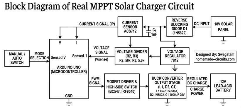
Here is the block diagram, I can only provide the block diagram and the schematic:
thank you so much.
that’s what I was looking
You are welcome!