In our previous articles, we learned how to build automatic street light circuit using a single transistor, an IC 555 timer and a solar panel setup.
Today we are going to investigate the fourth design from our collection which is a very popular and reliable automatic street light circuit using just two transistors and a relay.
If you want something slightly more sensitive and stable than a single transistor circuit without using any complicated ICs or microcontrollers, then this two transistor project is perfect choice for you.
Why Two Transistor Street Light Circuit?
When you use only one transistor, then sometime the change in LDR resistance during evening twilight is not enough to cleanly control a heavy 12V relay.
To solve this problem without adding IC, we can use two ordinary BC547 transistor together.
In this two stage design, the first transistor act as a voltage sensing comparator with LDR and the second transistor act as an inverter and relay driver.
This gives much better signal amplification and makes sure your relay switche ON and OFF sharply without any lazy behavior.
Required Parts List
To build this two-transistor automatic street light circuit, you will need the following electronic components:
- T1 and T2 = BC547 NPN transistors (two nos)
- LDR1 = Standard Light Dependent Resistor (LDR)
- R1 = 100K or 1M preset potentiometer (used for setting light sensitivity)
- Resistors (R2, R3 etc.) = 1K and 10K resistors (1/4 watt, 5% CFR)
- C1 = 100uF / 25V electrolytic capacitor (for power supply filtering)
- D1 to D4 = 1N4007 diodes (for the AC bridge rectifier)
- D5 = 1N4007 diode (used as a flyback protector across the relay coil)
- TR1 = 0-12V, 500mA or 1 Amp step-down transformer (or you can use a ready-made 12V SMPS adapter)
- RL1 = 12V relay (200 to 400 ohm coil resistance)
- LED Bulb = 220V or 120V LED bulb (100 watt or as per your street light requirement)
Safety Warning Regarding AC Main
Please remember that this circuit control a high voltage AC mains bulb (220V or 120V) through the relay contacts.
Working with AC power can be very dangerous and can cause severe electric shocks or fatal accidents if proper care is not taken then.
Always keep power disconnected while soldering or making wiring changes, use insulated tool and enclose the final circuit safely inside a well insulated plastic junction box so that no bare AC wire are left exposed outside.
Circuit Diagram
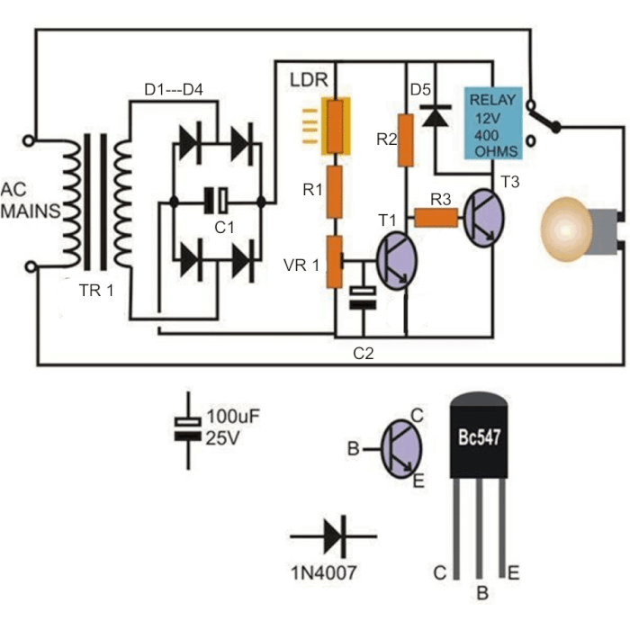
Basic Working Overview
The working of this two transistor circuit is very logical and easy to follow:
During Daytime: When bright sunlight falls on the LDR, then it internal resistance drop to a very low value. This low resistance pulls down the base voltage of first transistor T1, keeping T1 switched OFF.
Because transistor T1 is off, its collector voltage goes high which send positive bias current into the base of the second transistor T2.
Relay Status in Daytime: When transistor T2 gets base current, then it turns ON and activates the relay. Since your 220V lamp is connected to the Normally Closed (N/C) position or wired so that relay cut power during daytime, the street light bulb stays switched OFF while sun is up.
During Nighttime: When evening arrive and ambient light decrease, then the LDR resistance goes very high. This high resistance allows positive voltage via preset R1 to reach the base of transistor T1, turning T1 ON.
Switching ON Lamp: When transistor T1 turns ON, then its collector voltage drops immediately to ground level. This pulls down the base voltage of transistor T2, forcing T2 to switch OFF. When T2 turn off, then the relay is de energized, its contact change over and your 220V street light bulb turns ON automatically.
Detailed Working Explanation
The circuit can be used as an automatic day night operated light controller system or a simple light activated switch. Let’s try to understand the functioning of this useful circuit and how it is so simple to construct:
Referring to the circuit diagram we can see a very simple configuration consisting of just a couple transistors and a relay, which forms the basic control part of the circuit.
Of course we cannot forget about the LDR which is the prime sensing component of the circuit. The transistors are basically arranged such that they both complement each other oppositely, meaning when the left hand side transistor conducts, the right hand side transistor switches OFF and vice versa.
The left hand side transistor T1 is rigged as a voltage comparator using a resistive network. The resistor at the upper arm is the LDR and the lower arm resistor is the preset which is used to set the threshold values or levels. T2 is arranged as an inverter, and inverts the response received from T1.
How the LDR Works
Initially, assuming the light level is less, the LDR sustains a high resistance level across it, which does not allow enough current to reach the base of the transistor T1.
This allows the potential level at the collector to saturate T2 and consequently the relay remains activated in this condition.
When the light level increases and becomes sufficiently large on the LDR, its resistance level falls, this allows more current to pass through it which eventually reaches the base of T1.
How the Transistor Responds to LDR
The transistor T1 conducts, pulling its collector potential to ground. This inhibits the conduction of the transistor T2, switching OFF its collector load relay and the connected lamp.
Power Supply Details
The power supply is a standard transformer, bridge, capacitor network, which supplies a clean DC to the circuit for executing the proposed actions.
The whole circuit can be built over a small piece of vero board and the entire assembly along with the power supply may be housed inside a sturdy little plastic box.
How the LDR is Positioned
The LDR must be placed outside the box, meaning its sensing surface should be exposed toward the ambient area from where the light level is required to be sensed.
Care should be taken that the light from the lamps does not in any way reach the LDR, which may result in false switching and oscillations.
Important Pinout Reminders
Transistor Pinout Check: Always check pin configuration of both BC547 NPN transistors carefully before soldering.
Looking in flat side of transistor with the pins pointing down, left pin is Collector, middle pin is the Base and the right pin is the Emitter. Mixing up these pin will stop the circuit from working.
Relay Flyback Diode: Make sure diode D5 (1N4007) is connected in reverse bias across the two coil terminals of your 12V relay.
This freewheeling diode absorbs high voltage back EMF spikes when the relay turns off, then protecting transistor T2 from burning out.
Step by Step Setup and Calibration Guide
- After you solder all component carefully on your PCB or general board, follow these simple step to set it up:
- Connect your 12V power supply to circuit.
- Expose the LDR to exact amount of evening dimness or cover it partially with your hand to simulate dusk.
- Very slowly adjust preset potentiometer R1 until you hear relay click and your 220V LED bulb turns ON.
- Remove your hand to let room light fall on the LDR and bulb should turn OFF instantly.
- After you get the correct setting, apply a small drop of glue or nail polish on the preset knob so it never moves due to wind or vibration.
Important Troubleshooting Tips
Relay is Clicking or Blinking Continuously at Evening:
Cause: Optical feedback. If the light from your controlled street bulb falls directly onto LDR sensor, then the circuit gets confused, thinking day has returned, turning off the lamp and creating an endless blinking loop.
Solution: Always mount your LDR facing upward toward the open sky or inside a small dark plastic visor/shield so that light from the street bulb can never touch the LDR surface.
Bulb Stays ON Even in Daytime:
Cause: Preset R1 is adjusted too high, or transistor T1 is not receiving proper low resistance from the LDR.
Solution: Expose the LDR to bright sunlight and adjust preset R1 in the opposite direction until transistor T1 turns off and the relay release.
Relay Makes a Buzzing Sound:
Cause: Weak power supply or low voltage from your 12V transformer/SMPS adapter.
Solution: Make sure your 12V power supply can provide a steady current of in least 500mA to 1 Amp and check filter capacitor C1 (100uF/25V).
So friends, that's it for now...by following this simple guide, you should be able to successfully build your own reliable two transistor automatic street light circuit for your home or outdoor gate.


Need Help? Please Leave a Comment! We value your input—Kindly keep it relevant to the above topic!