In this post I have explained a simple non-contact cable tracer circuit which can be used for locating faults in long wound cables and wire bundles without a physical contact.
The Circuit Concept
Why would you shred $100 to buy a cable tracer when it is easier to develop one spending less than $10!
This kind of tracer are typically used by telephone mechanics or an electrician while layering, replacing or wiring any element which needs long cables for example intercom or security television.
The non-contact wireless cable tracer circuit as shown in the diagram comprises of two units. The first unit contains a multivibrator having output of 4v p-p on 5kHz (approx.), and is known as transmitter.
The second unit consists of a sensitive amplifier having capacitive input to detect transmitter’s tone.
It also has a magnetic pickup to detect magnetic lines of force carrying 240v from power cables and is known as receiver.
Moreover the inductive loop of the circuit is made of a specific length of wire, in order to detect stray signals from power cables. So in case one detector fails to detect signal, the second will detect the same.
Circuit Operation
This non-contact cable locator circuit has the capacity to steer a 3watt LED. However be sure to take utmost caution when you setup the circuit, as doing it in haste or on a wrong way may lead to the damage of LED.
Now add 10R to the supply and hold it firmly in your fingers. Ensure it doesn’t get hot and be vigilant on the resistors voltage. Every 1v represents 100mA.
This will lead to proper working of the circuit. Also be careful not to burn your finger as overheating and incorrect holding can lead to short circuit.
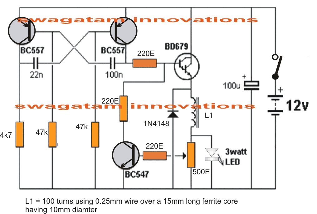
The BC557 multivibrator possess mark-to-space ratio and is laid down by 22n and 33k as compared to 100n and 47k, which produces around a ratio of 3:1. The BD679 is kept in ON state for around 30% of the time.
This actually results to brighter output and it takes around 170mA. It is not possible to measure the current with the meter since it reads only the peak value thereby an inaccurate reading.
It is only the CRO where it is possible to view the waveform and thereby calculating the current.
Using an Inductor for Illuminating LED Brightly
With the 100-turn inductor enabling the BD679 to turn ON in full, it clearly separates the voltage on BC679 emitter on top of 3 watt LED. As BD679 is turned ON, the emitter pushes to 10v whereas the top of LED remains at below or at 3.6v.
The indicator then buffers or separates the two voltages. It is done by generating a voltage crossing over the winding, which equals to 6.4v.
This is one reason for the LED not to get damaged. When the transistor goes in OFF state, the generation of magnetic flux by the current in the inductor crashes and effectively generates voltage on the other direction.
This process actually implies the miniature battery becomes an inductor and producing energy to illuminate the LED for a short span of time.
The indicators top becomes negative while the bottom remains positive. The resultant completion of the circuit is supported by the current flow through LD and the ‘Ultra High Speed’ IN4004 diode. This is way the circuit uses energy in the indicator.
Placing a 500R pot across the LED, the voltage is picked up to turn on BC547 transistor. In order to reduce the brightness of LED, the transistor takes help from BD679 transistor.
As the circuit drives the LED with pulse, it results to higher brightness which is procured from a very low current flow. It is easy to compare the brightness of light with one DC driven LED.
Submitted by: Dhrubajyoti Biswas
Circuit Diagram



Questions & Answers
Hi, sir
If you can, give me a few dates about L1.
Best regards!
Hi evulescu, you can wind any thin magnet wire over a ferrite rod or ferrite torroid. About 60 to 100 turns will be enough to fulfill the required results
Thank you so much, Swag!
My compliments.
My Pleasure Evulescu!
thanks for a nice circuit
please may you send me the transmitter circuit and the receiver one by Email
best regards
maher rihawi
which transmitter circuit do you want?
Non-Contact Cable Tracer Circuit.
I don’t understand the schematic notations. They don’t look to be standard. I never saw E or R for ohm’s (if I am reading this correctly). 500R in the notes and 500E on the schematic. Which one is it? and is it 500E o(or R) ohms or is it 500K ohms or something else?
Is 22n a non-polarity nano farad capacitor?
There is no 1N4004 diode in the circuit as your notes imply.
“Now add 10R to the supply and hold it firmly in your fingers.”
What is 10R and why isn’t it in the schematics?
Why do I have to hold it with my fingers to get the circuit working when there is a switch in the schematic?
Is CRO an oscilloscope ?
R and E both are used to signify the symbol Ω, since the symbol is not easy to write.
Whenever a capacitor is in nF or pF they are always non-polar, so the 22nF is also non-polar, it could be a basic ceramic disc or any other higher quality alternative.
The 10 ohm is probably used while setting up the circuit, and until the 500k is correctly adjusted such that in the absence of the external field, the LED remains shut off. The LED begins flashing only when the L1 is brought near the external frequency source.
So the 10 ohm is kept until the right adjustment of the 500k is accomplished, and then removed.
This circuit is not designed by me, it was submitted by an another author, so providing detailed troubleshooting may not be possible for me.
However the 3 watt led looks abnormal, it should be replaced with a 3V 20 mA high bright LED, and the input supply reduced to 4.5V
CRO is a scope for testing the waveform across the LEd.
The 1N4004 is actually the 1N4148 diode, mistakenly written as 1N4004
Thanks. This helps clarify a few things for me. Do you know if anyone has ever had any success building this and how accurate it is? If so please ask if you can share their email with me so i can get in touch. Thanks again for a great site.
I am not sure about the above circuit, bu the following one is a tested design:
https://www.homemade-circuits.com/how-to-make-non-contact-ac-mains-phase/
Will this circuit work if wires are buried in brick wall? If so, up to what depth? if no, what circuit modification will be needed to perform so?
I have not tested the above circuit so I am not sure how deep this circuit can locate a LIVE wire.
If you want sensitive circuits, then you can try the following versions:
https://www.homemade-circuits.com/how-to-make-non-contact-ac-mains-phase/
https://www.homemade-circuits.com/bug-detector-circuit-rf-sniffer-circuit/
Thanks for your prompt reply.