If you want to build a sensitive metal detector that gives a precise visual meter reading instead of just crude audio beeps then this LC tuned metal detector circuit is a great project to try.
It uses transistor oscillator combined with CD4046 Phase Locked Loop (PLL) IC and a CA3130 operational amplifier to detect tiny frequency shift caused by metal objects near search coil. Unlike the metal detectors discussed above, this 5th concept works under the rule that the frequency of an LC oscillator varies when there is modified inductance. To make that happen, the inductor is approached with any type of metal detector.
Basic Concept
The frequency change rate depends on the properties of the metal and on the frequency itself. If the latter is too high, a metal component will act like a shorted turn that brings down the inductance so that the frequency elevates.
In the event the frequency is substantially low for eddy-current losses to be neglected, we can then differentiate between ferrous and non-ferrous metals.
It will be quite challenging to make an oscillator frequency below 200 Hz. Due to that, the oscillator in the current circuit operates around 300 kHz. To make its inductance is quite simple and all you need is a single turn of a coaxial cable a depicted in the following figure.
How it Works
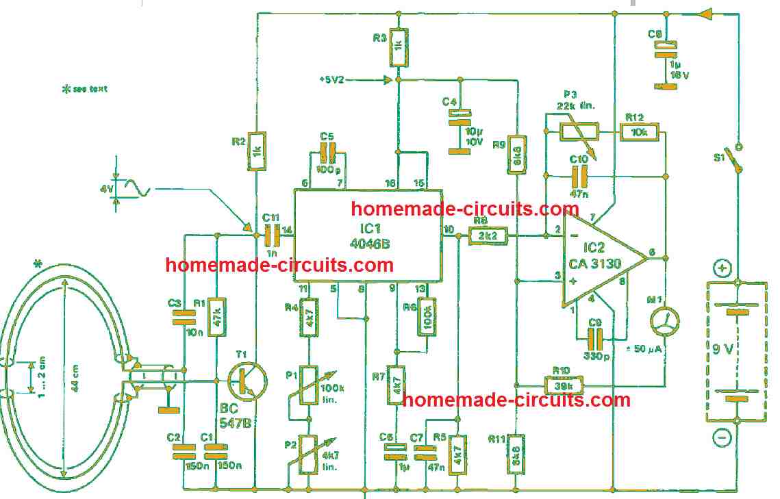
The LC tuned metal detector circuit is made up of an oscillator T1, a frequency-to-voltage converter IC1 and a BiMOS operational amplifier IC2. By employing a detector coil diameter of 400 mm, the values of capacitors C1 and C2 guarantee an oscillator frequency of 300 kHz. When smaller diameter coils are used, you will need more turns.
To supply the 4046B adequately, the oscillator signal strength must be around 400 mVππ. The phase comparator warrants that the internal phase-locked loop always locks at that level. At pin 10, the source follower input is supplied to a CA3130 where it is sufficiently amplified.
The main heart of this design is an LC oscillator network operating around 300 kHz where search coil acts as primary inductor. When you bring any metal piece like iron then copper, or gold close to search coil it changes the inductance and creates small electrical losses. This changes oscillator frequency. Instead of directly listening to the change through speaker, this circuit feeds the signal into a CD4046B PLL IC.
The PLL lock onto the frequency and track any minor deviation. Error voltage or output from the loop is then amplified using a CA3130 op amp which drive a 200 microamp panel meter to show the detection visually.
Parts List
| Component | Description / Value |
| T1 | Transistor (RF transistor or general-purpose NPN like BC547) |
| IC1 | CD4046B CMOS Phase-Locked Loop (PLL) IC |
| IC2 | CA3130 BiMOS Operational Amplifier |
| Search Coil | Custom air-core coil tuned for ~300 kHz operation |
| D1, D2 | 1N4148 Switching Diodes |
| Resistors | Various carbon film resistors (10k, 47k, 100k, etc.) |
| P1 | Preset Potentiometer for balancing and sensitivity adjustment |
| Capacitors | Polystyrene or high-stability ceramic capacitors for LC tank |
| Meter | 200 µA Analog Panel Meter |
| Power Supply | 9V to 12V Regulated DC Source |
Construction and Tuning Tips
Build oscillator stage first using stable components so your baseline frequency stays steady around 300 kHz. Wind your search coil carefully on a non metallic former using enamelled copper wire.
Keep turns tight and secure them with tape or epoxy to prevent movement drift.
Mount the search coil away from the main PCB or on plastic rod handle to avoid false triggering from hand movements or metallic screws. Adjust preset potentiometer very slowly during initial power up until the panel meter needle rest near zero or mid scale.
Bring small coin close to coil to check if the meter needle deflects smoothly or not.
Troubleshooting Tips
Meter needle swings wildly or stay pinned: Your oscillator frequency might be drifting or out of the CD4046 lock range. Check your LC tank capacitors and coil connection.
No response when metal is near: Verify that transistor oscillator is actually oscillating using an oscilloscope or frequency counter then. Check supply voltage stability.
False triggering from hand proximity: Ensure your search coil has proper shielding and that connecting wires are short and well routed.
Frequently Asked Questions
Can this circuit detect gold and silver?
Yes because gold and silver are conductive metals they will affect the electromagnetic field and cause frequency shifts picked up by PLL.
Can I use a speaker instead of a meter?
Original design is optimized for visual meter indication via CA3130 op amp but you can tap into the frequency output stages if you prefer adding an audio circuit then.
Why do I need regulated power supply?
Battery voltage drop can cause the oscillator frequency to shift, creating false readings. Stable 9V or 12V regulator prevents this drift, how deep can this metal detector reach?
Since this is a hobbyist LC tuned circuit with a moderate search coil small objects like coins can be detected up to a few inches deep, while larger metal object can be detected in greater depths.
How to Set up
Conveniently, P1 sets the centre frequency of the phase-locked loop and the zero of the centre-zero microammeter. Using P2, you can make fine adjustments if the sensitivity of the opamp is high.
Moreover, P3 sets the sensitivity in the discussion which is attached in a negative feedback loop to the inverting input. Notice there is a positive feedback through the microammeter and R10 to the non-in

Need Help? Please Leave a Comment! We value your input—Kindly keep it relevant to the above topic!