• Skip to main content
  • Skip to primary sidebar

Homemade Circuit Projects

Need circuit help? Post them in the comments! I've answered over 50,000!

Blog | Categories | About | Hire Me | Contact | Calculators-online
You are here: Home / Sensors and Detectors / Metal Detector Circuit Using IC CS209

Metal Detector Circuit Using IC CS209

Last Updated on November 11, 2026 by Swagatam Leave a Comment

The principle of operation of our 6th metal detector circuit is quite basic yet very interesting. The detecting function is triggered by sensing the decrease in the Q level of the LC network associated with the circuit in the presence of a metal at a specified proximity level.

Table of Contents
  • How to Set up the Metal Detector Circuit

Basically the built-in oscillator of the IC CS209 is made functional with the inclusion of a parallel resonant LC tuned network in conjunction with a feedback resistor wired up with the OSC and RF pin outs.

The impedance of the tuned resonant network may be expected at the maximum level as long as the driving source frequency is equal to the resonant frequency of the LC circuit network.

On detecting the presence of a metallic object at a close proximity to the inductor sensor, the voltage amplitude of the LC network gradually begins to fall corresponding to the closeness of the metal to the inductor.

Due to the above factor when the oscillation frame of the chip drops and reaches a certain threshold level, triggers the position of the complementary outputs such that they change states.
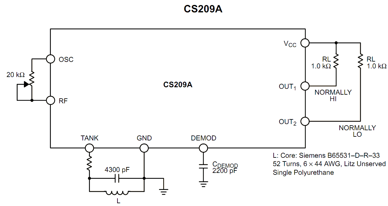
Metal Detector circuit Using IC CS209

The precise technical the operations may be understood as follows:

Referring to the figure, as soon as a metal object is detected at the inductor input, the capacitor connected to the DEMOD gets charged through an in built current source of 30 uA.

However during the detection process the above current gets deviated away from the capacitor proportionately with the generated negative bias on the LC network.

Therefore the charge from the capacitor is removed attached to DEMOD with every negative cycle generated across the LC network.

The DC voltage with ripple over the capacitor of the DEMOD is then directly referenced with an internal fixed 1.44 voltage level.

When the procedure forces the internal comparator to trip, it switches the transistor which introduces a 23.6 K Ohms in parallel to the given 4K8 resistor.

This resulting reference level then equals near about 1.2 volts which introduces some sort hysteresis in the circuit, and becomes ideally suited for preventing wrong or false triggering.

The feedback pot connected across the OSC and the RF is used for setting the detection range of the circuit.

Increasing the resistance of the pot, in course increases the range of detection and subsequently the tripping point of the outputs.

However the detection and the trip points may also be dependant on the LC configuration and the Q of the LC network.

How to Set up the Metal Detector Circuit

The proposed metal detector circuit may be set up initially by following the below described steps:

Position a metal object at relatively larger distance away from the inductor, assuming the Q of the LC to be at the maximum sensitivity and the distance to be within the allowable range provided by the Q factor of the inductor.

With this set up adjust the pot such that the outputs just shift states indicating the detection of the metal object.

Repeat the adjustment procedure by gradually increasing the distance until a suitable maximum sensitivity of the circuit is optimized.

Removing or displacing the metal manually should make the output of the circuit to revert states, confirming the perfect working of the circuit.

Though the circuit is able to detect metals within a range of 0.3 inches, the range may be suitably increased by increasing the Q of the inductor.

The Q factor is directly proportional with the sensitivity of the circuit and the degree of detection.

Filed Under: Sensors and Detectors

About Swagatam

I am an electronics engineer and doing practical hands-on work from more than 15 years now. Building real circuits, testing them and also making PCB layouts by myself. I really love doing all these things like inventing something new, designing electronics and also helping other people like hobby guys who want to make their own cool circuits at home.

And that is the main reason why I started this website homemade-circuits.com, to share different types of circuit ideas..

If you are having any kind of doubt or question related to circuits then just write down your question in the comment box below, I am like always checking, so I guarantee I will reply you for sure!

Previous Post: « LC Tuned Metal Detector Circuit

Reader Interactions

Need Help? Please Leave a Comment! We value your input—Kindly keep it relevant to the above topic! Cancel reply

Your email address will not be published. Required fields are marked *

Primary Sidebar

Categories

  • Arduino Projects (95)
  • Audio and Amplifier Projects (134)
  • Automation Projects (18)
  • Automobile Electronics (104)
  • Battery Charger Circuits (90)
  • Datasheets and Components (109)
  • Electronics Theory (153)
  • Energy from Magnets and Earth (43)
  • Games and Sports Projects (11)
  • Grid and 3-Phase (20)
  • Health related Projects (27)
  • Home Electrical Circuits (13)
  • Indicator Circuits (16)
  • Inverter Circuits (111)
  • Lamps and Lights (183)
  • Meters and Testers (72)
  • Mini Projects (28)
  • Motor Controller (68)
  • Oscillator Circuits (30)
  • Pets and Pests (15)
  • Power Supply Circuits (92)
  • Remote Control Circuits (50)
  • Security and Alarm (65)
  • Sensors and Detectors (120)
  • SMPS and Converters (52)
  • Solar Controller Circuits (63)
  • Temperature Controllers (44)
  • Timer and Delay Relay (51)
  • Voltage Control and Protection (44)
  • Water Controller (37)
  • Wireless Circuits (31)

People also Search

555 Circuits | 741 Circuits | LM324 Circuits | LM338 Circuits | 4017 Circuits | Ultrasonic Projects | SMPS Projects | Christmas Projects | MOSFETs | Radio Circuits | Laser Circuits | PIR Projects |

My YouTube Channel

Circuit Simulator: Draw and Simulate Schematics

circuit simulator image

Subscribe to get New Circuits in your Email

Other Links

  • Privacy Policy
  • Cookie Policy
  • Disclaimer
  • Copyright
  • Videos
  • Sitemap

Recent Comments

  • Swagatam on IC LM393 Complete Datasheet with Circuit Diagram
  • Swagatam on Induction Heater Circuit Using IGBT (Tested)
  • Swagatam on Calculate Battery, Transformer, MOSFET in Inverter
  • Swagatam on Rat Repellent Circuit Diagram
  • Jeff on IC LM393 Complete Datasheet with Circuit Diagram

Social Profiles

  • Twitter
  • YouTube
  • Instagram
  • Pinterest
  • My Facebook-Page
  • Stack Exchange
  • Linkedin

Calculators

  • ZVS Induction Heater + Tank Calculator Tool
  • Zener Diode Calculator
  • Wire Current and Thickness Calculator (Ampacity Calculator)
  • Resistive Voltage Divider Calculator
  • Transistor Base Resistor Calculator
  • Transistor Astable Multivibrator Calculator
  • TL431 Calculator
  • Solar Panel, Inverter, Battery Calculator
  • Ferrite Core Air Gap Calculator Tool
  • Parallel MOSFET Calculator Tool: How to Connect MOSFETs in Parallel Safely
  • LC Resonance Calculator for EV Battery Charger Circuits
  • LED String Series Resistor Calculator
  • PFC (Power Factor Correction) Calculator Tool: 3kW
  • Passive Power Factor Correction (PFC) Calculator
  • LM567 IC Calculator Tool
  • SMPS Flyback Boost Converter Calculator
  • Shunt Resistor Calculator for Ammeters
  • SCR and Triac Gate Resistor Calculator
  • Battery Back up Time Calculator
  • Boost Converter Calculator (Non-Isolated)
  • Bootstrap Capacitor Calculator
  • Buck Converter Calculator
  • Buck-Boost Converter Calculator
  • Capacitance Reactance Calculator
  • DCM Flyback Transformer & Wire Gauge Wire Size Calculator Tool
  • Filter Capacitor Calculator
  • IC 4047 Calculator (Frequency and PWM)
  • IC 4060 Calculator
  • IC 555 Astable Calculator
  • IC 555 Monostable Calculator
  • IC SG3525, SG3524 Calculator
  • Inductance Calculator
  • Induction Heater Inductor and Resonant Frequency Calculator
  • Induction Heater Work Coil Calculator
  • Inverter LC Filter Calculator
  • LC Resonance Calculator
  • LED Current Calculator
  • LM317, LM338, LM396 Calculator
  • NAND/NOT Gate RC Values Calculator
  • NOT, NAND Gate Frequency Calculator
  • Notch Filter Calculator Tool
  • Ohm’s Law Calculator
  • Phase Angle Phase Shift Calculator
  • Power Factor (PF) Calculator
  • RC Filter Calculator
  • Reactance Calculator
  • Sine Table Calculator for SPWM Arduino Code
  • Small Signal Transistor(BJT) and Diode Quick Datasheet
  • SMPS Calculator for Toroidal Ferrite Transformers
  • SMPS Flyback Transformer Calculator – Design by Target Duty Cycle
  • TL431 Calculator
  • Op-Amp Hysteresis Resistor Calculator

© 2026 · Swagatam Innovations