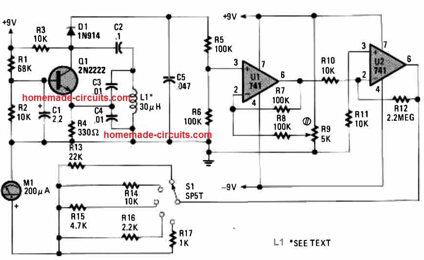
This metal detector simply employs all of the common components, as shown below. It utilizes a 2N2222 transistor and a couple of 741 ICs. Even the detector coil is as simple as it can be!
Basic Working
Op amp U1 works like as a differential amplifier to zero the varying DC, and U2 is used to boost the signal over a 200 µA meter. To use the simple metal detector circuit, fine-tune the potentiometer until the meter M1 reaches at the midscaleof the dial.
As soon as a metal object such as gold, tooth fillings, etc come to a close proximity of the coil's field of view, small alterations in the amplitude of the frequency waves trigger changes on the meter reading. Switch S1 works like an attenuation or sensitivity selection switch.
Complete Circuit Working
This circuit is 2n2222 and 741 op amp metal detector shown in schematic. It uses single transistor radio frequency oscillator combined with two operational amplifiers to show metal detection visually on an analog meter instead of generating an audio tone.
Looking in left side transistor q1 is a 2n2222 wired as a colpitts oscillator.
Resistors r1 and r2 provide base biasing while capacitor c1 is connected to the emitter and r4 is a 330 ohm emitter resistor.
Inductor l1 which is a 30 microhenry search coil form the main resonant tank network together with matching capacitors c3 and c4. when powered by the +9 volt rail this stage oscillate continuously in high frequency then.
Diode d1 1n914 rectify the high frequency oscillator output into dc voltage level.
When a metal object approaches search coil l1 it changes inductance and energy losses of the coil which alters the overall oscillation amplitude then.
This altered dc voltage is fed into pin 3 of first 741 op amp u1. u1 is configured as differential balancing amplifier.
Resistors r5 and r6 set a reference voltage divider on pin 3 while potentiometer r9 help balance the circuit so the user can manually zero the meter reading when no metal is near the coil then.
The output of u1 on pin 6 passes through r10 into the second 741 op amp u2. u2 acts as an additional high gain amplification stage using feedback resistor r12 and resistors r10 and r11 to boost the small voltage shift caused by metal disturbing the search coil field.
Final output from pin 6 of u2 drives meter m1 which is a 200 microamp analog meter.
Switch s1 is an sp5t rotary switch connected to various shunt and range resistors r13, r14 r15, r16 and r17 allowing operator to adjust meter sensitivity.
The op amps operate on a dual power supply using both +9v and 9v rails to maintain proper linear signal processing.
How to Wind the Coil
You just need to wind 8 turns of 22 SWG super enameled copper wire over a 9 inch diameter former.
After finishing the winding, secure the coil using strapping or a strong adhesive and gently pull it off and remove from the former. Transistor Q1 works like the main component of a Colpitts oscillator. Diode D1 rectifies the frequency from the Colpitts oscillator to a certain varying DC.
Parts List
| Component | Part / Value | Description |
| Q1 | 2N2222 | NPN transistor configured as a Colpitts oscillator |
| U1, U2 | 741 | Operational amplifiers (differential balancer and high-gain amplifier) |
| D1 | 1N914 | Switching diode for rectifying RF oscillator output |
| L1 | 30 µH | Search coil (main inductive sensing element) |
| M1 | 200 µA | Analog meter for visual detection indication |
| S1 | SP5T | Rotary switch for selecting meter sensitivity shunt resistors |
| R1 | 68K | Transistor biasing resistor |
| R2, R3, R10, R11, R14 | 10K | Resistors |
| R4 | 330Ω | Emitter resistor |
| R5, R6, R7, R8 | 100K | Resistors (bridge and feedback balancing) |
| R9 | 5K | Potentiometer for manual meter balancing/zeroing |
| R12 | 2.2M | Feedback resistor for second op-amp gain |
| R13 | 22K | Meter range/shunt resistor |
| R15 | 4.7K | Meter range/shunt resistor |
| R16 | 2.2K | Meter range/shunt resistor |
| R17 | 1K | Meter range/shunt resistor |
| C1 | 2.2 µF | Electrolytic capacitor |
| C2 | 0.1 µF | Ceramic/film capacitor |
| C3, C4 | 0.01 µF | Tank circuit tuning capacitors |
| C5 | 0.047 µF | Decoupling/filter capacitor |
| Power | ±9V | Dual DC power supply rails |
Frequently asked questions
what is power supply requirement for this circuit?
The circuit requires a dual plus 9v and minus 9v dc power supply to operate op amps properly.
What does meter m1 show?
Meter m1 is a 200 microamp analog meter that shows visual deflection when metal disturbs the search coil then.
What is function of switch S1?
S1 is an SPDT rotary switch connected to various shunt resistors like R13 through R17 to change sensitivity range of the meter.
Does it make any sound?
No this specific design is built for visual indication on meter instead of producing audio tones through a speaker.
Troubleshooting tips
Meter needle cannot be zeroed using potentiometer R9
Check the resistor divider network formed by R5 and R6 and ensure the op amp u1 power connection for plus 9v and minus 9v is correct.
No meter movement when metal approaches search coil L1
Verify that transistor Q1 is oscillating correctly check if diode D1 is soldered properly and make sure tank capacitor C3 and C4 are connected across coil L1 then.
Erratic or jumping meter readings
Check for loose wiring around search coil or power supply rail and ensure proper grounding to avoid electromagnetic interference.

Need Help? Please Leave a Comment! We value your input—Kindly keep it relevant to the above topic!