This metal detector principle discussed below is fairly well-known, as can be seen in the block diagram in Figure 1.
The detector is made up of a large coil acting as an antenna, which is coupled with a capacitor and an amplifier to form an LC oscillator. When the antenna coil approaches a metal mass, the resonance frequency of the LC oscillator is altered. To detect this change in resonance, the signal from the main oscillator is mixed with that of a second oscillator tuned to a frequency very close and as stable as possible. The resulting signal contains the beat frequency of the two oscillators.
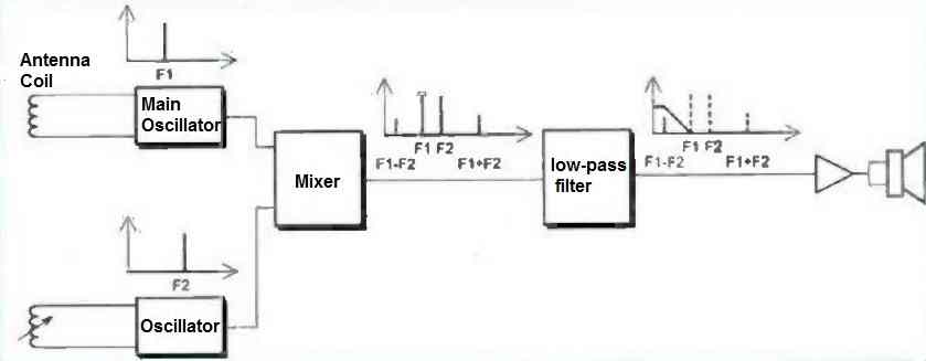
By tuning the secondary oscillator so that the beat frequency becomes audible, it is then easy to isolate the audible signal using a good filter, and then amplify it to drive a small audio headset. The frequency variations of the audio signal will immediately inform the operator of the proximity of a metal mass.
The human ear is capable of detecting very small variations in the frequency of the audible signal, making it easy to detect small metal fragments with such a device.
How the Circuit Works
The diagram of our setup is shown in figure 2. The main oscillator is centered around transistor T1. The operating frequency of this oscillator (F1) is set by C3, C1, and the antenna that will be connected to CN1.
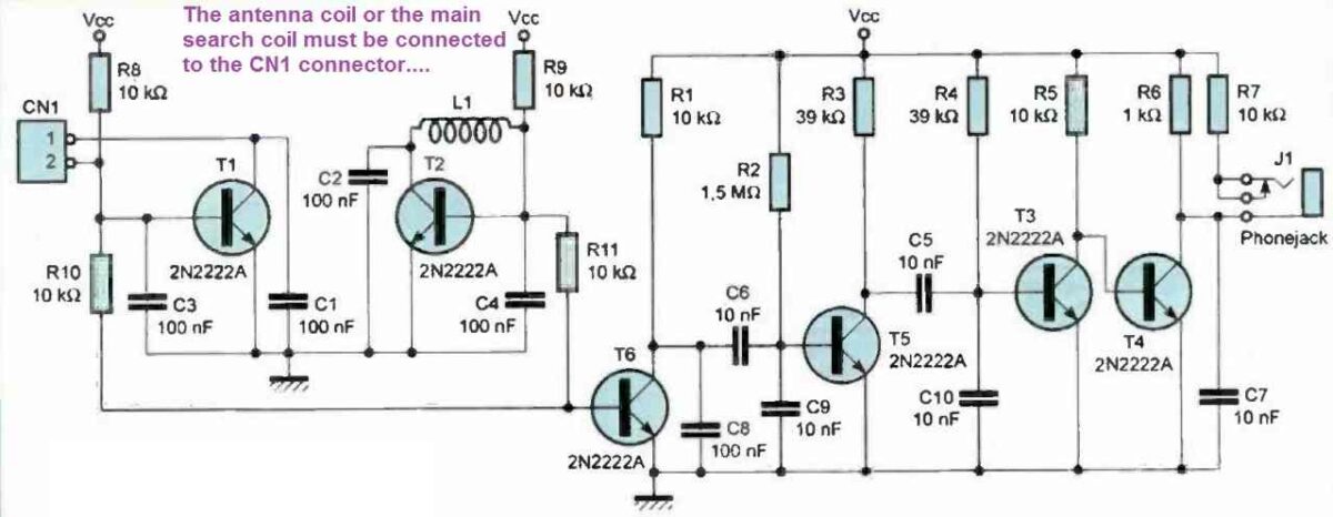
As for the secondary oscillator (frequency F2), it is centered around transistor T2, associated with C2, C4, and L1. Both oscillators will be tuned to a frequency close to 120 kHz.
Resistors R10 and R11 allow us to take the signals produced by the two oscillators and mix them at the base current of T6.
The alternating component of the voltage appearing across R1 is the result of the two mixed signals. If you observe the signal with an oscilloscope, you will see a signal with a frequency of 120 kHz modulated in amplitude at the beat frequency F3 = F1 - F2.
Capacitors C8, C6, and C9 will strongly filter the main frequency of the signal (120 kHz) to finally let only the low part of the spectrum pass through.
The signal obtained across R3 is already the audible signal we are interested in, and it only needs to be amplified through transistors T3 and T4.
The amplified signal will be used to drive an audio headset equipped with small speakers of 32 S2 via J1. Resistor R7 is used to limit the sound level of the signal imposed on the headphones.
We have not provided a sound level adjustment for this setup. If you wish, you can replace R7 with a 100 S2 resistor, after which you only need to mount a 10 k potentiometer in series with the headset.
Power Supply
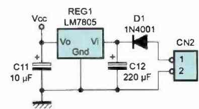
This detector can be powered by a small 9V battery connected to CN2, with diode D1 used to protect the setup against reverse polarity. We use a regulator (REG1) because the tuning frequency of the L/C oscillators is quite sensitive to changes in the power supply voltage.
Given that our setup operates by analyzing the frequency difference between the two oscillators, even slight changes in the power supply voltage would immediately be audible.
Therefore, we preferred to use an LM7805 regulator to spare you from this kind of inconvenience.
However, note that there is another important source of frequency drift in our setup. This is due to the environmental conditions of the L1 inductor that tunes the secondary oscillator.
Indeed, the impedance of this inductor is also sensitive to magnetic fields. Special precautions must be taken during its implementation, as we will see later.
PCB Designs
The printed circuit board design for this setup can be seen in Figure 3. The associated layout view is reproduced in Figure 4.
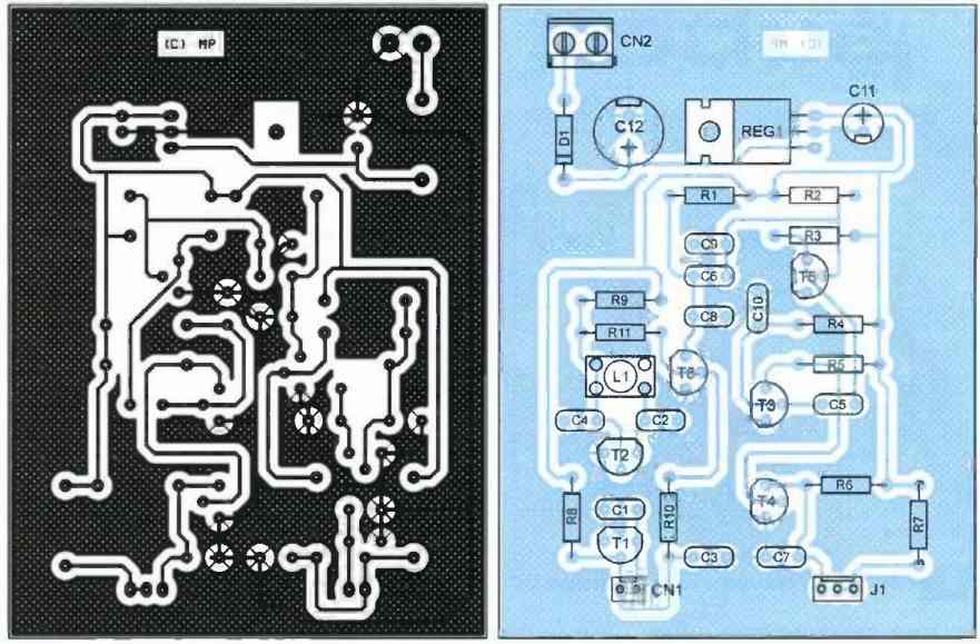
Most of the pads will be drilled using a 0.8mm diameter drill bit. For the pads of the connectors, diode D1, and regulator REG1, a 1mm diameter drill bit will be needed.
Apart from the coil winding, there are no particular difficulties in building this circuit. However, pay attention to the orientation of the transistors and capacitors C11 and C12. The selected components are common and should be readily available at your usual supplier.
How to Construct the Antenna Coil
Now let's move on to the coil winding. The antenna coil must be constructed with great care, as its characteristics directly affect the sensitivity of the circuit.
To do this, you will need to find a cylindrical support with a diameter of around 12 cm (10 cm to 15 cm can also be suitable).
The support used to make this coil must be chosen from a material that does not interfere with magnetic fields (plastic is an excellent choice). For example, the base of certain CD boxes may be suitable (boxes of 25 stacked CDs).
To make the antenna, you will need to wind 10 turns of enamelled wire (wire diameter: 0.2 mm to 0.3 mm), well aligned and tightly packed. Once the winding is done, the enamelled wire must be immobilized with glue (hot glue, for example).
As the enameled wire is quite fragile, it is preferable to solder a connector to the ends of the coil wire (don't forget to scratch the enamel with sandpaper to ensure direct contact with the copper).
In this way, you can easily change the position of the antenna without worrying about breaking the enameled wire by manipulating the coil.
How to Construct the Oscillator Coil L1
The second coil (L1 on the diagram) will be mounted directly on the printed circuit board. It will be made using a winding support with a diameter of 6.5 mm and a ferrite core to allow tuning of the secondary oscillator's frequency.
Initially, you will need to wind 120 to 130 turns of enamelled wire (wire diameter: also 0.2 mm to 0.3 mm). Later, as we will see in the next paragraph, you will remove turns until you achieve a very close frequency match between the two oscillators.
How to Setup and Tune the L1 Coil
To adjust the L1 coil, proceed as follows. Connect the antenna and headphones to the circuit and turn on the device.
Be careful to place the antenna more than 50 cm away from any metal mass and also keep it away from the L1 coil during the entire tuning phase. Initially, place the ferrite core of L1 at the top.
Using a non-magnetic screwdriver (fully plastic), slowly submerge the core in the middle of the turns until a sound signal is heard in the headphones.
If you cannot obtain this sound signal when moving the core from one end to the other, you will need to remove 10 turns from the L1 coil.
Then, you will need to repeat the L1 tuning process until a sound signal finally appears (otherwise remove another 10 turns, etc.).
For your information, if you use the same antenna support as us (10 turns on a diameter of 12.5 cm), the L1 coil should have 100 turns.
Once the tuning of L1 is complete, you can immobilize the wire with glue (to maintain its mechanical characteristics).
It should be added that this circuit is very tolerant as the working frequency of the L/C oscillators can range from 50 kHz to 200 kHz. Therefore, you should not experience significant difficulties in making your prototype work.
How to Test
Once the adjustment of L1 is complete, the use of this detector is very simple. Adjust the ferrite core of L1 so that the frequency of the sound signal is very low.
Then, bring a coin close to the antenna to check that the frequency of the sound signal increases as the distance between the coin and the antenna decreases. If you notice that the frequency of the sound signal decreases instead of increasing, it means that the tuning frequency of the secondary oscillator is the highest (F1 - F2 < 0).
In this case, simply move the magnetic core until the beat frequency is canceled, then continue to move the core in the same direction so that the sound signal reappears (but with F1 - F2 > 0 this time).
Don't forget that there can be coupling between the antenna coil and L1. Make sure to maintain a distance of at least 20 cm between the setup and the antenna.
Furthermore, the relative position of the setup and the antenna should be kept as stable as possible (so that the residual coupling remains constant and does not cause a slight drift in the beat frequency, which could decrease the sensitivity of the setup).
It is therefore preferable to fix it (in a box) on the handle of the detector.
In this case, add a switch in series with the power supply, as we did not plan one on the printed circuit. Also, provide access to the bolt to adjust the position of the L1 coil core.
Indeed, you will certainly have to adjust the tuning frequency from time to time, as our setup does not aim to compete with professional equipment (the effect of external temperature is quite sensitive).
In practice, this is not too problematic because the frequency of the sound signal does not drift suddenly. Your ear will be able to distinguish between the slow variation of the reference oscillator and the abrupt variation of the beat frequency due to the appearance of a metallic object in proximity to the antenna.
When you go out in the field, make sure to bring a non-magnetic screwdriver with you for adjusting the L1 core if needed.
We will conclude this article with an important warning. It is important to know that the use of a metal detector is regulated (both in public and private domains) and requires au

Need Help? Please Leave a Comment! We value your input—Kindly keep it relevant to the above topic!