A Fence charger or energizer is an equipment which is used for charging(electrifying) a fence or a boundary in order to protect the inside premise from human or animal interventions.
Since these boundaries are mostly of large fields and parks, are normally away from the main cities, and powering them through some renewable option becomes more suitable than from utility grids which may become difficult to acquire in such remote areas.
The circuit of a solar electric fence charger explained here does not depend on traditional power source for operating, rather gets it 24/7 from a self sustained solar power conversion set up.The circuit is very simple to understand.
The fence charger circuit is basically a switching circuit which involves a few diodes and a high voltage capacitor.
How the Circuits Works
The diodes are used for rectifying the AC from a small step up transformer so that it gets stored inside the high voltage capacitor.
When this voltage reaches a particular threshold, the SCR fires and discharges the entire stored voltage inside the capacitor.
The above discharging of the capacitor is done or rather dumped inside the primary section of an automobile ignition coil.
The sudden dumping of the above high voltage inside the ignition coils primary, steps up the surge into several thousands of volts into the secondary winding of the ignition coil.
This stepped up voltage is used for energizing the fences or the boundaries appropriately.
However the above operations requires an AC input at the levels of around 100 to 220volts.
This voltage is generated by suitably processing the input DC from a solar panel set up.
The voltage from the solar panel is first controlled to a suitable level and then it's used for operating a triggering circuit.
The triggering circuit consists of a IC 555 oscillator which switches the voltage obtained from the solar panel controller into the transformers input, so that the output from the transformer generates the required 220V AC for powering the ignition circuit.
The solar panel output also charges a small 12V/7AH battery so that the power can be used after dusk, when sun energy is not available.
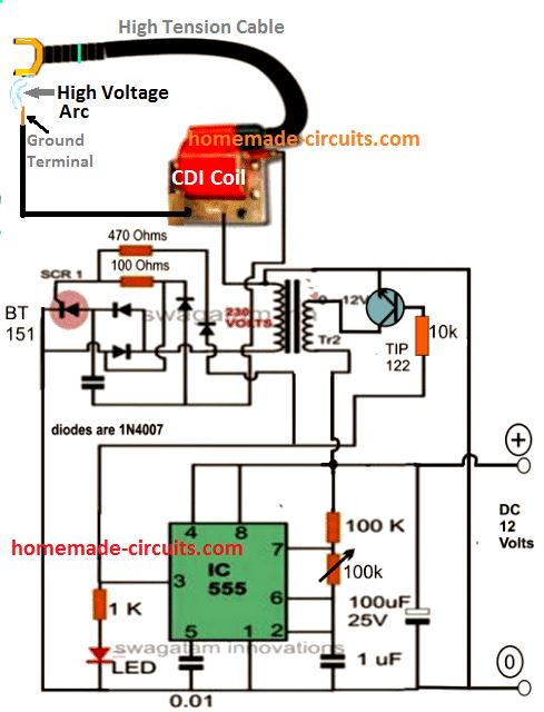
Parts List
- 10k, 100k, 1k 1/4 watt 5% = 1 each
- 470 ohms, 100 ohms 1/2 watt 5% = 1 each
- preset 100k = 1no
- Capacitor 1uF/25V, 100uF/25V electrolytic - 1 each
- Capacitpr 0.01uF disc ceramic = 1 no
- Capacitor 105/400V PPC = 1no, near the SCR
Semiconductors
- 1N4007 = 4 nos,
- IC 555 = 1no
- LED red 5mm = 1no
- Transistor TIP122 = 1no
- SCR BT151 = 1no
- Transformer = 0-12V/220V 1 amp
- Ignition Coil from 2-wheeler or 3-wheeler
The above circuit can be powered through the following solar panel current controlled battery charger circuit:
For complete explanation of the circuit please refer this solar voltage regulator circuit.
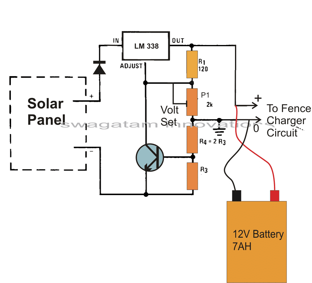
Parts List
- R1 = 120 ohms
- P1 = 10k pot (not 2k)
- R4 = replace with link
- R3 = 0.6 ohm 1 watt
- Transistor BC547 = 1no
- IC LM338 = 1no
- Diode 1N5408 = 1no
- Solar Panel = 16 V / 2 amp
- Battery 12 V 7 Ah
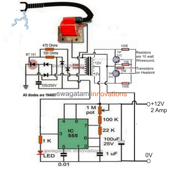
Fence Charger using a Stand-alone Inverter
Video clip showing the working details of the fence charger circuit. The video basically highlights the strength of the sparks generated by the CDI coil and how effectively this can be used when integrated with a farm fence.



Questions & Answers
yes it's possible by adjusting the 22K resistor, make the 22k resistor variable, this will allow you to select any desired pulse timing.
what are the components for the charge controller circuit given above?
transistor is BC547, rest is given in the diagram
hello swagatam… here u have used TIP122 instade of BC547 transistor…… which is correct..?
sir howmany kilometers can use this circuit.
with iron wire not more than 100 meters.
Great post. What is the output pulse waveform? is it a square wave?
Thanks, I am not sure about the waveform, so can't say.
hello… swagatam.
in ckt what is the value of capacitor just below the scr 1.
and value of capacor at pin 5 in IC 555 is .01 uf…?
hello kalpesh,
the value of the capacitor is 1uF/400V or 105/400V
pin5 cap is = 0.01uF or 103 ceramic disc
btw i m working on ur ckt diagram …. it's really good.
and in second ckt… battery charger ckt what is the value of R1, R2(p1),R3,R4 .
THOUGH SOME OF THEM U HAVE PROVIDED. and transistor is also BT151 in second ckt…?
please click the diagram to enlarge.
R4 is not required, could be removed.
R3 = 0.6 x 10/battery AH
BT151 is for SCR1, the transistor in the charger circuit is BC547
thank u swagatam bhai ,
but i m facing 1 more problem that i can't get ic LM338 and scr BT151 so can u suggest me any other equivalent ic & scr … so i can get it…!
Hi Kalpesh, I am afraid there's no other reliable alternative for these two devices, because the specifications of these parts are unique and ideally suited to the proposed application, so I won't recommend any other equivalent because they could burn and get damaged overtime
Hy i have used bc 547 and when ckt start uts burn any idea also still i have not connected the ugnitiin coil in this
BC547 has no chance of burning, something may be not correct in your circuit.
hello sir
thanks for putting circuit.i am student of engineering and my project is solar fence guard.
in first stage i use step up transformer 12v/230v and charge capacitor.in next stage i discharge capacitor in output transformer.required output transformer is 230/10 kv but i dont know current rating of 230/10kv transformer.please suggest me the current rating of 230/10kv transformer.and what is its frequency.
hello vikas,
divide 10kv with the secondary voltage of the transformer
frequency will depend on the oscillating frequency that you may be using to drive the trafos.
Hi Swagtam this is Suhas. Your circuit looks good.
Currently Im building this but dont know how to check output high voltage and current ??? Please suggest.
Also send your you-tube video link for this project.Thanks.
Hi Suhas, if you are asking regarding the solar panel measurements, it may simply done by connecting your multimter (in DC V range) prods directly across the solar panel terminals under peak sunshine, this will show you the voltage specs (open circuit voltage) of the panel, for measuring current you need to follow the same procedure again, but by keeping the meter in the DC ampere range…the reading will show you the amp spec of the panel (short circuit current)
I'll wait for the video and pics if possible…thanks!
In the schematic P1 calls for a 1M potentiometer. later it is referred to as a 27K preset. Did you change it to a resistor?
I don't remember actually, but that may be possible, I might have changed the 27k to a 1M… because a 27K preset will generate a much higher range of frequency than the 1M preset which might not be suitable for the associated iron core transformer.
Does the 12 v Battery used to power the fencer circuit have to be 7AH or will any 12 v battery work? will a car battery damage anything?
the AH of the battery value can be anything, it won't affect the circuit as long as the voltage is within 15V
When I apply power to the circuit the tip122 locks on and just buzzes I know if I leave it powered it will burn the tip122 out what could be the cause I have double triple checked the work and cannot find the problem. any suggestions would be greatly appreciated.
that's not possible, if the IC555 works correctly, it's ought to oscillate the TIP122 and the transformer accordingly at the set frequency.
Increase the base resistor of the TIP1222 to 10K and the check the response.
if the trafo is an iron core type, then make sure the frequency does not exceed 100 to 200Hz…I think might be crucial to keep the TIP122 and the trfao cool
swagatam will u arrange the solar fence tested circuit pcb
would be difficult due to lack of time…
Is transformer tr2 a pulse transformer or simple transformer??
it's an ordinary iron core transformer
Hi sir,
1) is output of 555 timer used to apply gate pulse to SCR?
2) why have you connected output of 555 to transformer?
3) can we use tl 494 instead of 555 timer?
Hi Umar, the CDI coil requires at least around 100 to 200V to produce the specified 20,000 volts, that's why the transformer is used for stepping up the 12V to this level.
TL494 can be used instead of IC 555
what changes we have to do for lower output say 10KV.?
P.S. thank you for quick reply…
use 6V DC supply input
1)sir what is current rating of transformer tr2?
2)what is the rating of 100, 470 ohm connected to scr, and 100 ohm connected to tip 122?
TR2 can be any small transformer such as a 0-12V/500mA/220V or a 0-12V/1amp/220V.
SCR resistors can be 1/2watt rated
The TIP122 base resistor should be above 1K, @ 1/4 watt………100 ohm is incorrect.
Sir what is the function of tip122?
to switch the transformer at the 555 frequency
Sir, which is the primary side of induction coil? Is it the one with which the capacitor is connected or the one with which cathode of scr is connected?
And my second question is whether 555 is also controlling the scr?
Umar, the capacitor side is the primary of the CDI coil.
555 is controlling the CDI coil by switching TIP122, TR2, and the SCR, in a sequence…
thank you sir…
sir, is the combination of tip 122, transformer , and 555 , making a fly-back converter?
yes it is suitable.
is the polarity of transformer tr2 is same or opposite?
it will be the same, low voltage side towrads the transistors and the high voltage side towards the output
sir, i meant what's the polarity according to dot convention? whether dots are on same side or on opposite sides?