In this post I have explained an upgraded version of my previous mains 220V/120V high-low voltage cut off protection circuit which now includes a delayed restoration of power for the load with 3 LED power status indicators.
The idea was requested by one of the dedicated members of this website.
Circuit Objectives and Requirements
- I just followed you're explanation and is it possible that you can help us with the following:
- To design a safety circuit that should provide for household appliances for over-and under-voltage protection.
- The protective circuit must immediately switch off upon detection of low-and high-voltage household appliance and upon detection of normal voltage switch on again after 3 minutes.
Main Specifications
The protective circuit must comply with the following: If the line voltage is within the normal range (100 to 130V ac), it will wait for the protective circuit 3 minutes before the output will be energized. During these 3 minutes there is an amber
LED light. If the line voltage is outside the normal voltage, the output of the protective circuit will never be under tension. If the line voltage is less than 100VAC, the protection circuit "low voltage" must indicate by a red LED that lights up.
If the line voltage is present, the protection circuit must pass a voltage greater than 105 Vac "normal tension" it will indicate by a green LED that lights up.
Similarly, the line voltage protective circuit has to be higher than 130V ac "high voltage" will be indicated by a red LED that lights up. Only when a voltage is less than 125VAC, it must indicate the protection circuit "normal tension" by a green LED that lights up.
Upon detection of over-and under voltage protection, the circuit should give a beep of 5 seconds.
This should be constructed with an opamp oscillator circuit in this functionality.
Circuit Diagram
The Circuit Design
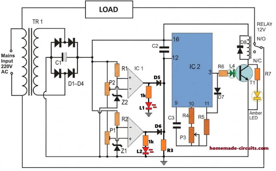
The above shown mains high/low voltage cut off protection circuit is an enhanced version of my previously explained design which had similar high low cut off protection feature except the delay timer stage which has been added in the present design as per the request.
The timer stage ensures a delayed power switch ON for the load each time the mains is cut off due to an abnormal fluctuating voltage so that the load is never subjected to an abrupt or random voltage switching situation .
The circuit also includes 4 distinct LEDs which indicate the corresponding mains voltage levels or status through their individual colors. The two red colors indicate high and low voltage situations respectively, the amber color LED indicates the intermediate delay counting status of the circuit, while the green LED informs the user regarding a healthy mains output condition.
The P3 preset or pot is used for setting up the delay time switch ON for the IC 4060 stage
How it Works:
We already know from our previous post that whenever the input voltage crosses the higher threshold, a logic high is created at the output of the upper opamp and when the voltage drops below the lower threshold the lower opamp generates a high logic at its output.
This implies that during both the conditions a high logic is generated at the cathode junction of the diodes connected with the opamp outputs.
We know that the timer IC 4060 is forced to reset in the presence of a positive trigger at its pin#12, and the IC stays disabled (output open) as long as a high is sustained at this pinout of the IC.
Therefore for so long the output from the opamps is held positive, pin#12 is kept high and subsequently the IC 4060 output pin#3 is held deactivated, which in turn keeps the relay switched OFF along with the mains load disconnected through the N/C contacts.
Now as soon as the mains voltage returns to its normal level, the high logic at pin#12 of IC 4060 is removed, so that the IC is allowed to commence its counting process.
The IC now begins counting as per the values set by C3/P3. Supposing the mains remains stable during the whole counting process, the IC counting finally elapses enabling a logic high at its pin#3, which triggers the relay and the load into action.
However suppose while the counting was in progress, the mains kept fluctuating, the IC would be forced to reset repeatedly and this would keep the output completely switched OFF making sure that the load was never allowed to face the unpredictable and fluctuating mains condition.
How to Set Up the Circuit.
Initially keep the power supply disconnected with the circuit.
Apply mains input to the power supply transformer and measure the DC output across the filter capacitor, and also measure the existing input mains level at the input of the transformer.
Let's say the mains voltage is found to be around 230V, which results in the production of a DC output of around 14V.
Using the above data now it may be possible to calculate the corresponding upper and lower cut off thresholds, which may be used for setting up the respective presets .
Suppose we want 260V to be the upper cut off level, and 190V as the lower cut off, the corresponding DC levels could be calculated with the help of the following cross multiplication:
230/260 = 14/x
230/190 = 14/y
where x represents the corresponding upper cut-off DC level and y the lower cut-off DC level.
Once these values are calculated, using a variable DC power supply, feed the upper DC level to the circuit and adjust the upper preset such that the upper opamp LED just lights up.
Next, in a similar fashion apply the lower DC level and adjust the lower preset until the lower opamp LED just lights up.
That's it! The adjustments for the upper high, and lower under voltage cut-off setting up procedures are complete, and the system can be now be plugged-in with the mains for the actual test.
Parts List
- R1, R2, R3, R4, R7 = 4K7
- R6 = 4K7
- R5 = 1M
- P3 = 100K POT
- C2 = 0.33uF
- C3 = 1uF
- C1 = 1000uF/25V
- P1,P2 = 10K PRESET
- Z1, Z2 = 4.7V/ 1/2 WATT
- D1---D4, D8 = 1N4007
- D5----D7 = 1N4148
- IC1 = LM358
- IC2 = IC 4060
- T1 = BC547
- RELAY = 12V/250 OHMS, 10 AMPS
- L1----L4 = LEDS 20mA, 5mm
- transformer = 0-12V/1 AMP or 500 mA
UPDATE
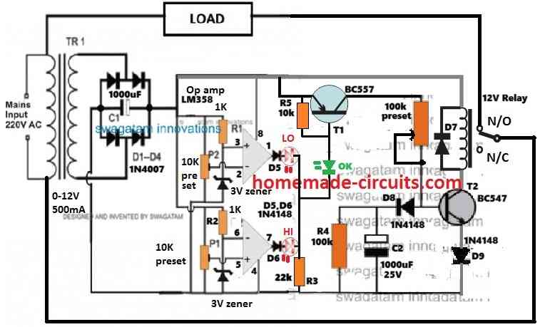
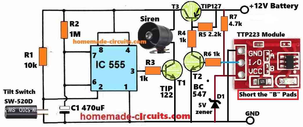
For a transistorized version of the above high/low mains protection with delay timer, you can try the following design:


Questions & Answers
The circuit will short mains through relay contact
check it now
SIR YOUR CIRCUIT DIAGRAM IS LUCID BUT YOUR LABELLING OF NO AND NC CONTACTS OF 12V RELAY IS QUITE CONFUSING. THEY SEEM TO BE INTERCHANGED.
Hello Moses, the N/O and N/C connections of the relay are correctly mentioned in the diagram….
I want to increase the delay time. 10minit
increase the value of C3
Hello, just seen your circuit of the over/under voltage protector. this is a very good circuit. My only concern is the mains transformer. If there is going to be a high voltage greater than 260v from the line this will definitly blow the transformer's primary winding. Any ideas, can one include a vdr to protect the transformer?
Thanks.
Bontech
Hi, thanks,
yes, above a certain level the transformer itself might become vulnerable of getting burnt, a simpler and effective approach could be to go for a triac based crowbar circuit across the primary of the transformer.
the crowbar could be set to trigger at around 260V using a 260V zener diode which would finally blow off the series connected fuse and cut the supply.
This is very valid question and a much more useful advice.
sir.
I have a doubt. No need connection in pin no 4 and 8 on LM358 ??
Raghu, obviously it will be required, I might have not shown it by mistake, but it’s an understood fact, without powering the IC pinouts the IC cannot work….
Pls mention that which one is -ve pin and which one is +ve pin.
And what’s the value of C3 ?
1mf ? Or 0.1mf ?
whenever in doubt always check the datasheet of the IC for LM358 pin#8 is (+), and pin#4 is (-)
You not mention the polarity of C3
C3 should be non-polar.
sir it’s a good work l always believe your circuits they don’t fail thanks my great teacher and a good master
thanks emapi, if you build them by understanding the concepts well, the circuits will never fail…appreciate your thoughts.
pls my teacher am trying to work on a meter that can read the resistance of the ground pls help me out.
You mean the degree or the level of “earthing” ground??
please sir, can you kindly help me with only 12v battery low voltage cut off circuit diagram
kabiru, you can try the concepts explained in the below article
https://www.homemade-circuits.com/how-to-make-simple-low-battery-voltage/
thank
Hi,
Thanks for this kind of website for sharing knowledge . It is really nice.
My question is that I want to
use this circuit for 2 phase power supply .
How can it will ?
Hi Thanks, do you mean single phase power supply? I have never heard 2 phase power supply.
Hi , I want to use this circuit on 2 phase submersible motor .
What is the input supply for the pump.
It’s 3 wire input in starter panel.
2 line wire and 1 neutral wire
What is power input? Is it 220V single phase?
Helo sir I love your circuit but my major concern is the labeling or naming of those components used in the circuit.
Please help me by naming the components pls…
Hi Akinbi, the schematic includes all standard symbols which can be easily recognized, you will have to get well versed with the basics of electronics in order to identify them correctly.
I have built the circuit but when T2 is in the circuit the relay operates regardless of any thing ,second the circuit operates for only 2s regardless of time delay seted. waiting for your help…thanks.
Thanks for informing regarding this isue, it could be due to the positive from the BC557 emitter interfering with pin#11 of the IC.
Please remove the entire T2 stage, and connect the yellow LED and its series resistor across collector/emitter of the T1.
Dear sir, thank you for your quick reply ,I will try your suggestions ,moreover in your article about cd4060 a capacitor is connected from pin 11 to ground which is not present in the circuit is it important. Lastly can you explain how to check cd4060 working or not …my great regards to you.
Hi Mohammad,
Can you please show me where I have mentioned this? Pin#11 of IC 4060 does not require any capacitor
Tanks alot please,can you check the circuit in your article under ic4060stage ,calculating RC components for timing and see c2 is connected to pin#11.The high low voltage section is working very nice .thank you again.
Thank you Mohammad, I am glad it is working…. but I still couldn’t find pin#11 related issue, is it in the above article or some other article??
Hello sir, pls can i use 555 timer instead of cd4060 for the timing? How can i do
IC 555 can be difficult to customize as per the given objective, but transistorized circuit may be possible instead.
Thank you for a very useful circuitry and a detailed description about the working and setup of the same.
Wanted to clarify if all capacitors are polarized ?
Thank you! Only C1 is polarized rest are non-polar
Hello,
Your circuit is very good.
My question is that how it is alter if I donot want to use transformer and relay also in this circuit to achieve the same result?
The transformerless/triac version is also given in the above article. Connect the delay timer in place of the LOAD, and connect the motor at the output of the delay timer
I have not seen transformerless/triac version in the above article. Can you please tell me if it is on another link?
“Connect the delay timer in place of the LOAD, and connect the motor at the output of the delay timer”
in above so ask for “delay timer”.you mean delay timer circuit or delay timer sold in market?
I think I had referred you this article in your previous comment on some other post:
https://www.homemade-circuits.com/highly-accurate-mains-high-and-low/
so I thought that you were in this linked article.
For the circuit on this page you can add a transformerless power supply in the same way as done for the 3rd circuit in the above link.
I have checked you link “https://www.homemade-circuits.com/highly-accurate-mains-high-and-low/”, but the problem is that this lacks delay timer. And you have said that “Connect the delay timer in place of the LOAD and then connect the motor on output of delay timer”, it confuses me that first I have to built the circuit mentioned above and then make another circuit mentioned on “https://www.homemade-circuits.com/highly-accurate-mains-high-and-low/” and connect as you said.
My Question is that is it not possible to add some alteration in circuit mentioned at link “https://www.homemade-circuits.com/highly-accurate-mains-high-and-low/” to achieve delay result? I think it is more practical as easy for me and starter hobbiest. I do not want to use relay which is mentioned in this article and I like delay option mentioned in this article. And on other hand your article “https://www.homemade-circuits.com/highly-accurate-mains-high-and-low/” have the option which I like is Triac base option but it lacks delay option.
I want to build 1 circuit with blend of your both articles to acheive the following results:
1: Triac based with out relay
2: Delay time
Regards,
I had provided you two links in your earlier comment, so the connection details was referenced to those two links.
You can add a 1000uF capacitor across base/emitter of T1 in the following circuit to get the required delay:
https://www.homemade-circuits.com/highly-accurate-mains-high-and-low/
Dear Swagatham
I am planning to build your above circuit.
My transformer is 220VAC primary to 12VAC-0-12VAC, 1amp secondary transformer. As I know the RMS secondary DC (after rectification and filteration) voltage is 12VAC *1.414=16.968vdc. Is it correct….?
So what will be corresponding secondary DC voltages for:-
Primary voltage=210VAC (lower limit)
Primary voltage=250VAC (upper limit)
Thanks in advance.
Dear Anil Kumar,
Your calculation is correct, but here we only need the RMS, the peak voltage may not be necessary.
First you will have to find the practical transformer secondary voltage that corresponds to the input AC volatge.
Let’s say it is 220V (must be verified practically) primary that produces 12V at the secondary, then the calculations can be done using simple cross multiplications, as shown below:
220/210 = 12/L——-This is for low voltage.
220/250 = 12/H——-This is for high voltage.
Dear Swagatham,
The second paragraph in your reply cleared my whole doubts. Till this day it was a burden for me and many others like me to set the Hi-Lo cut off point without a variac or some other devices.
What is the purpose of Z3….?Can we simply avoid it….?
Thank you verymuch.
Glad it helped you Anil,
Yes you can remove Z3, it is not important.
Hi thanks for detailed circuit. But I did like to know the amps of the circuit.
And I will be glad if you would help me with similar circuit but 30amps
Hi, the current handling capacity will depend on the relay contact specs, for 30 amps please use a 30 amp relay.
Okay, thanks Sir. I will do that right away
Dear Mr. Swagatam, Thanks for your circuit ideas.
I am a Sr. Citizen hobbist and engaged in my electronic hobbies with simple circuits useful for home appliances. Recently my fridge Stabiliser went off and I wanted to repair the circuit.
First my background. We stayed in Delhi for last 40 years where in there is peculiar problem of very low voltage mains supply which is mostly around 160-170 V AC. So my Fridge stabiliser was designed with step down transformer of supplying boost up secondary voltage accordingly.
Now we have moved to Pune and the AC supply is 250 V AC. My stabiliser is giving problem of stabilised supply ( for aforesaid boost up volatge) at 300 V AC. The mains Transformer of the stabliser has 5 taps ( secondary) of these 2 are giving 250 V AC while remaining 3 are giving 300 V AC output.
The Transformer tapping supply to the control circuit is 17 V AC step down with circuitry of 4 nos BC 547 and wired RC networks.
In summer , due to overloading, sometimes the AC mains goes temporary to 160 V AC and my fridge shakes violantly.
Now I want to use your valuable Low/Over Voltage circuit with built in PCB supply of 17 V AC inlieu of 12 V AC.
I shall wire out your components in this circuit but now Pl. let me know the variations in resistor/zener/capacitor values to adopt to 17 V AC supply from secondary of same transformer.
Also pl. let me know if you sell PCB readymade for the purpose.
This circuit shall certainly help me to protect under and high volatge supply to fridge with using same stepdown transformer and metal box assembly.
Thanking you in advance.
Wishing for a reply.
Dear Mohan ji, Thank you for your interest and for visiting my site!
For 17V supply no changes would be required in the circuit except the supply pin connections of the IC1, IC2 and the relay. The 17V will need to dropped to 12V through a 7812 IC for feeding the pin16 of IC2, and pin8 of IC1, and the relay positive line.
I wish you all the best with the construction, let me know if you have further problems.
Mains High Low Voltage Protection Circuit with Delay Monitor
Refer your Reply :
Dear Mohan ji, Thank you for your interest and for visiting my site! For 17V supply no changes would be required in the circuit except the supply pin connections of the IC1, IC2 and the relay. The 17V will need to dropped to 12V through a 7812 IC for feeding the pin16 of IC2, and pin8 of IC1, and the relay positive line. I wish you all the best with the construction, let me know if you have further problems.
Dear Sir,
Thanks for your reply to my querry. Further, I would request to please denote/show the IC1 Pin connections which are apparently not shown in the circuit diagram published.
Another querry is the Relays in my Fridge stabiliser unit are 18 V DC rated where as the above circuit is designed for 12 V DC operation. I am afraid the relays may chatter due to under volatge of operation ( 12 V DC as against 18 V DC) and may not function properly. So, is any change/modification is required for the Relay operation voltage? or alternatively if I operate the circuit at 17 VDC , will it affect functioning of ICs ?
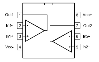
Thank you, I have updated the IC pin diagram in the above article, you just have to replace the pin numbers accordingly, in the main diagram.
If you have 18V relays, then the relay positive can be directly connected with your 17C DC, only pin#8 and the pin#16 of the two ICs will need to be fed through a 7812 IC regulator.
Sir: You specified a 1 amp Transformer for this circuit but a 500MA transformer for the previous design which looked to be more power hungry than your updated design. Question: I am having difficulty sourcing a 12va 230 volt transformer for this new upgraded circuit. Can I use a 6VA transformer? Where do you source your parts? Also, you have stipulated a BC557 Transistor for T2 but I do not see a T2 transistor on the schematic. Thank you for your patience and help.
Charles, 1 amp transformer is more easily available than 500 mA, therefore I mentioned a standard 1 amp transformer, you can use a 500 mA if you wish to.
BC557 was earlier used at the output of IC1, but later on removed…I have removed it from the list now. You can use a 6 V transformer if the relay is also a 6V relay.
Nice Circuit, Can I replace Z1 and Z2 with 7805?
yes you can, but that would be unnecessarily expensive.
Thank you for reply, i Will build the circuit with recycled components, in my country is almost impossible get them new. Thank you for your good work, i recently discoverd this site and i have to say is awesome.
OK, Thanks for the feedback, Glad you liked my site.
Hi it’s a very nice circuit idea .
I want to use this in 3 phase submersible motor for agricultural use .
If use please sent me the Gerber file also for the pcb fabrication .
Thanks in advance
Akash, The above circuit is for single phase input, and I am not sure how to convert it into a 3 phase, if i happen to figure it out I may update it here soon.
Thanks for the reply. Waiting for the update .
Also can u please provide Gerber file for this 1 hp circuit.
Thanks in advance
Sorry I do not have the gerber files, you will have to contact a PCB designer for that
Respected sir your circuit diagram is useful I’m going to build this but kindly give me example for adjustment of low and high cut off my math is weak. I have 220v ac mains and 14v dc. I want to cut off on 260 and 170 volts kindly give an example or provide how many dc voltages I should supply for upper and lower settings?
Muhammad, you can use the following formula:
220/170 = 14/a
220/260 = 14/b
Dear sir, I have another question that I have already created such like circuit with lm324 which works well but there is a problem that I have set the low voltage to 10.1v problem is when the low voltage goes near to it the relay creates chattering sound means when voltage goes to 10.4 etc? How can I tackle this? Kindly help
Hello Muhammad, you can connect a 470uF/25V capacitor right across the relay coil terminals to prevent the chattering.
I am keen on making this project. My query is , is anyone making a PCB [unpopulated or populated ]
Please mention person’s comment time in you template. This will help us to know when a person commented. and this will also help to decide when necessary alteration/amendment are being made by reading comments.
Dear Swagatam,
First of all i appreciate you for designing such a useful,reliable and simple circuit for every one.
I have one doubt will this give a power on delay when the power is switched on initially and also whenever the power fails and come back every time if so how it works sir.
V.Sambath kumar.
Thank you V.Sambathy, the delay is created by the IC. Whenever input power in the normal range is switched ON, the IC is reset by C2, which enables the IC to resume the delay ON counting process and after the predetermined period its output pin3 is triggered high, and is latched via diode D7, ….until power is switched OFF and ON again manually or due to power outage.
Dear Swagatam,
Thank you very much for your
detailed reply now I got it.
Sorry for the delay in my reply
I was shifting from my rented house.
V.Sambathkumar.
You are most welcome V.Sambath!
Dear Swagatam,
If we isolate the relay coil voltage using a7812 reg from the same dc voltage ,will this
help in improving the circuit sensing performance
Regards V.Sambath kumar.
Isolating the relay voltage with 7812 output is OK, it will help to reduce current consumption of the circuit slightly, that’s the only improvement you will get….sensing performance will not have effect, unless the power supply current is inadequately rated
Dear Swagatam,
Thank you once again.
Regards V.Sambath kumar.
You are welcome V.Sambath!
Dear Swagatam,
Now we are powering the rly coil and the sensing circuit voltage from the same rectified dc voltage. suppose if we connect a 7812 reg to the cathode of the rectifier diode and connect the out put pin of the reg to the rly coil with out disturbing the sensing circuit will it make any sense.
Regards V.Sambath kumar
Dear Sambath, If you fix the voltage at 12V, the circuit will not be able to sense or respond to voltage changes.
Dear Swagatam,
Sir i do agree with you , but what i mean is that the relay connection coming to pin 16 of ic tobe disconnected from that point and to be connected to the 12v reg out put pin all other connections remain same ie all other connections as per the diagram connected to un regulated supply which should not make any problem for the relay drive transistor and the op amp sensing Ckt also the holding current of the will not have much change giving more life for the relay what is your opinion if I am wrong you can correct me.
Regards, V.Sambath kumar.
Dear V.Sambath, that’s fine, you can do that, but a few voltage difference will not have any significant effect in the relay’s life, since it is an inductor its working voltage specifications has a wide range
Swagatam,
Paul England here again.
Can SN741’s be used in this circuit instead of LM358’s?
Also the relay is shown as only having a contact carrying capacity of 10A. For any heavy duty inverter this could be much more and I have not come across may relays that would have this capability.
Hello Paul, yes IC 741 can be used….you can use automobile relays which are rated at 30 amp current for the contacts.
Hi.
Please can I have the circuit transformersless .
Thank you
Hi, I have designed it for you below….but remember it is not isolated from mains so extremely dangerous to touch in open and powered condition
Everything is good. I have a question for you. Why did you use a transformer, when almost everyone uses a capacitive source? Is there no other way to isolate the circuit instead of the transformer? Thanks you. Joakín
You can use an SMPS based adapter instead of a transformer based power supply. Capacitive power supply is not recommended since it is not isolated from the mains.
Thank you so much dear Swagatam.
Can you help me please with the scooter converter 36V 60º. The thechnic info in the box says it support 60º and 120º, but it is set for 60º and I need make it for 120º, since I got a Hub motor 120º. I sen the photo of the PCB. Please help me or at least say me which door to knock.
Thank you
Joakin
You are welcome Joakin, sorry I do not have any information regarding the question you have asked!
Hello sir I’m grateful with your support on many other circuits, yours circuits works well.
pls can you assist me with a under voltage circuit with the following functions: make relay active when voltage is below 180 and relay off when voltage is in normal range
Thank you Chris, you can try implementing the following circuit for your under voltage cut off application: The D5 diode can be removed….
Hello sir I have Constructed the the transistorized version of your circuit and it’s working well but needing assistance on the delay time. I need a delay time of 5 seconds to 10 sec
Thanks Chris, I am glad you could build the transistorized version successfully. You can set the output delay by adjusting the 100k preset. However make sure to connect another 10K in series with the 100k preset for safeguarding the transistor from an accidental short circuit while adjusting the preset. Also please change the BC547 into a Darlington pair by connecting another BC547 with it in the Darlington mode, this will ensure that even if the 100k preset is adjusted to a higher resistance value, the relay can still be activated without issues.
Thanks a lot for your support
My pleasure!
Hi sir can you please assist me with upgrade on the transistorized version? I want to use 24v relay instead of 12v
Chris, you can supply 24V for the same set up, just be sure to use 10K for the op amp zener resistors, and replace 12V relay with 24V relay. The 1000uF capacitor voltage rating must be also changed to 35V
Hello sir, can pls assist with the delay circuit of the transistorized version?
Delay time is not constant, it changes if supply voltage is applied intermittently.
You can try adding another BC557 with the BC547 in the following manner to increase the accuracy. For 24V supply use a 24V relay
Hello sir, thanks for your support but having issue with the transistorized version. BC557 is still active if High or Low LED lilts. what could be the problem or should add a Zener diode after D5 and D6?
Hello Chris,
To turn OFF the BC557 fully, the positive output from the op amp must be equal to the emitter voltage of the BC557. Because of the two red LEDs the op amps are not able to produce enough positive voltage to block the BC557 emitter voltage.
You can try two things to rectify this.
Increase the 1K value associated with the lower op amp (near D6) to 22K or 33K or 47K.
Or put a few 1N4148 diodes in series with the emitter of the BC547.
Thanks you sir
…In the last sentence I have mistakenly mentioned BC547, it should be BC557 instead….
Sir pls can this network also work? if 2 IN4148 are connected in series for both low and High Outputs and LEDs connected to the middle of the two IN4148 through a series resistor to Groundfile:///C:/Users/CHRIS/Desktop/GOOD/Untitled.jpg
No, That will not work, you should do exactly as I mentioned in my previous comment.
The link you sent is not opening.
Please how can I include crowbar circuit to protect the trafo. Diagram circuit please
You can try one of the designs from the following article:
https://www.homemade-circuits.com/simple-dc-over-voltage-protector/
Hello,
How did you select your components? Let me say how did you calculate the values of the resistors and capacitors?
Hello, In any electronic circuits mostly the resistor values are not too critical, so any intermediate value works, but to select these you must have some prior experience and knowledge regarding the working of the relevant parts. For example the resistors R1 and R2 at the op amp inputs can be be anywhere between 1K and 100K because the op amp input pins are high impedance so the value does not matter, only the ratio matters. However, if the resistor values are above 10K, then the associated zener diodes might not fire and clamp correctly, that is why we have stopped at the 10K value here. However, the presets P1, P2 can be of any value between 1K and 100K for the same reasons and because no zener diodes are involved here. The base resistor for a relay driver transistor can be 10K for most 12V relays. Here it is furthermore selected such that the LEDs are bright enough to see. Capacitors depend on complementary resistor values to set a delay time, so these capacitors are mostly selected and set with some trial and error, until the requirement is fulfilled.
So basically the values of the resistors and capacitors depend on what and which components are associated with them and how critically these components depend on their values.
Sir what is the power on delay time of the transistoried version.
Sambath, it will depend on the value of the 100K preset adjustment. You will have to test the results practically with trial and error.
I have made the without delay opamp and transistor version but its not working.
It is a straightforward opamp comparator circuit, and it has to work….please check your circuit stage wise…
Nice design, please where can I add surge protector circuit. ( In the output or input section) Thanks
Thank you, however a surge protector may not be required since we already have a delay ON timer which effectively prevents the initial switch ON surge.
Greetings
Dear Swagatham,
The transistor version while working when it turn off and turn on the delay fail to work.delay is not discharge immediately to next on.please do a solution.
Regards,
Sison
Hi Dr. Sison,
the transistor version will produce the delay only during power switch ON. The delay has to happen, because the 1000uF base capacitor will charge slowly which will not allow the transistor relay to switch ON immediately, rather wait until the capacitor is fully charged. You can adjust the 100K preset to full resistance value meaning adjust it to full 100K resistance and check again.
How to use 24v relay on transformerless , transistorized version of the circuit
You can use a 9-0-9V transformer to get 18V AC output which after rectification and filtration will produce 25V DC for the circuit. This DC can be used for powering the circuit. The relay will also need to be replaced with a 24V relay. The capacitor voltage ratings must be increased to 50V.
Sir what if I want to use 24v relay on transformersless circuit pls advise
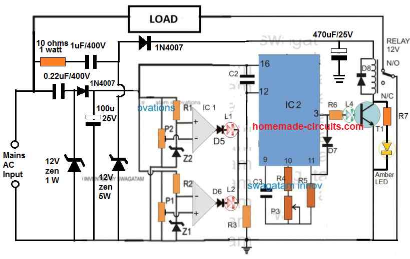
Hi Jas, I am sorry, I noticed it just now, there’s a serious mistake in the transformerless version shown below…you can see the dc supply to the opamp inputs is stabilized with a 12v zener diode, that means the opamp will not able to detect the ac voltage fluctuations, and therefore cannot detect and respond to the input ac fluctuations….that is why a transformer based circuit is recommended, as explained in rhe above article.
Can u provide same transistorized version circuit for 24v relay on 24v or 12v transformer
You can use the same circuit, nothing will change except the transformer and the relay. The transformer must be rated at 0-18v, 1 amp, and relay can be a 24v relay. The capacitor voltages must be rated at 50v or higher.
Sir
Will 24v relay coil works on 18v from transformer or it will need to boost
Jas, after full bridge rectification and filtration the 18V DC will become 25V DC which will be enough for the relay.
Sir
In transistor version zener is 3v Or 6v
Hi Jas,
The zener can be any value between 3V and 6V.
Hello, good afternoon, my name is Carlos and I am interested in the circuit but I would just like to know if you have a simple circuit that when the 220VAC network fails deactivates the relay, but when the power returns it has a delay of about 2 to 5 minutes to come back on. energize the relay.. Thank you very much in advance
Hello Carlos,
you can try the second circuit from the following article:
https://www.homemade-circuits.com/simple-refrigerator-protector-circuit/
In transistor version relay continuesly working no matter voltage is up or down
Please remove the red LEDs and check again.
I’ll check and reply
Sir
Relay still contact if we applied 18 v as I set upper cutoff at 14.2 v
Did you remove the red LEDs? and now how much voltage are you getting at the cathodes of the D5, D6 diodes? Is the green LED always ON?
Yes I removed red leds if I in 23 v I get 20v at diode junction green is on and relay contacts if I give 14.2 v I get 12.6v at diode junction and relay still contact
Please compare the diode junction voltage with the base/emitter voltage of the BC557 transistor. If the base/emitter voltage is higher than diode junction voltage then the bc557 will always ON. You can try increasing the 1k at the diode junction to 22k or higher until the green LED shuts off…or you can try adding a 1k across the base emitter of the bc557.
Ok what I have done is that pls correct me if I’m done anything wrong while adjusting low high presets
My low is 8.6v and high is 14.2
I set preset low and high with both voltage untill red led glow or I get voltage from op amp outputs
Yes, you have to get a high from one of the opamp outputs, either at high voltage or at low voltage, both opamp outputs cannot be high together.
No sir
I’m unable to make this don’t know what I am doing wrong relay contacts at high voltage Or tell me how to configure high and low opamp presets as while I giving 14v at high out put diode I get 12 v at some point of preset and 0 at last setting how to configure it properly I know I’m making mistake here somewhere
You can do the following just for testing purpose but it is not the final setting.
Let’s say you have 12v relay, and the low voltage limit is 11v and high voltage limit is 14v.
Now take a variable DC power supply and feed 11v to the circuit and adjust the upper opamp preset up/down until its output becomes just high.
After this increase the voltage to 14v, this should instantly cause the upper opamp output to become low….now adjust the lower opamp preset up/down until the lower opamp output just becomes high…now reduce the DC input to 12v, now both opamp output should become low….subsequently now increasing the DC to 14v must cause the lower opamp output to go high, and reducing the DC to 11v must cause the upper opamp output to go high….at 12v both opamp outputs must stay at 0v
Sir during 12v input 0v output from cathode junction but using bc547 single transistor without delay model relay not contact and 12v shows on relay coil
Hi Jas, sorry I couldn’t understand what you are saying
Do you mean you have removed the bc557 stage and connected the bc547 relay stage directly with the opamp output, and the relay is ON even while the opamp output is zero?
Yes sir i connect bc 547 with relay but relay not working
Relay will operate when the opamp supplies a voltage to the base of bc547.
How
Ok i input 8.5v and adjust upper opamp preset till it giving just give me output volts around 6.5 v and input 14.5v lower opamp preset adjust when I get output around 12v , now by adjusting both presets I get same voltages not higher or I get 0v, I set both preset when I get voltages above 0v but at between voltage like 9v to 13v no output from opamp kindly help
Jas,
I cannot understand your English.
If your your opamp output is high at 8.5v and 14.5v and 0v between these two limits then your circuit is working correctly.
Sorry for english
Ok ill tell what I’m done
I got 9 0 9 trans
And using 9 and 0 after bridge and cap I got around 12v ok
On ic lm358 pin no. (2) I connect 1k resistor and other end of resistor to +ve supply and same pin( 2) I connect 5v zener cathode and zener anode to ground
Pin no. (3) I connect 10k vr middle pin and other two pins connected +ve and -ve supply, pin no. (1) is output
On pin no. (5) I cionect 10k vr middle pin and other two pins to +ve and – ve supply
On pin no. (6) I connect 1k resistor and other end of resistor to +ve supply and same pin (6) I connect 5v zener cathode and zener anode connect to ground
Pin no. (7) is output
I’m using 12v relay coil one side connected to +ve supply and other end to bc 547 emmiter, bc 547 collector connected to ground, base connected to cathode junction
I think you made a mistake. The two opamps are oppositely configured. One opamp has preset on its (+) input and the other opamp has the preset on its (-) input….same for the zener diodes.

Please check the updated diagram below:
I’ll check and reply
Ok…
I made it temporary using your previous transistor version with delay circuit and working good, just if I want to cut at 14.2v it cut relay at 14.4v but anyways thanks will post final results
Ok, sounds good, you can improve the accuracy by using better quality presets or by using multiturn presets.
Hi by bypassing red leds it works but if using both leds relay connect automatically tried the updated circuit also
OK, please connect a 1N4148 diode in series with the green LED, and check again.
Hi now with diode it’s working good just green led glow continues on high and low
Try connecting green LED at the emitter line of the BC557, on left side of R5, and check the results,
No it’s still glow
Bring back the green LED at the base of T1, and now connect two green LEDs in series at the base and check the results.
I’ll check and reply
Hello, good afternoon, Mr. Swagatam. I am really interested in building this circuit… The problem is that here in Italy, iron transformers are not easy to find… Everything is switched… The question is, can it be done without a transformer, with a capacitive source? Thank you very much.
Thanks you Carlos, yes that’s possible, you can find the diagram in the following article:
https://www.homemade-circuits.com/highly-accurate-mains-high-and-low/
Hi Swagatam,
Q.1 : I want to make “High-Low cut off protection circuit with delay timer stage” (With LM358 & IC 4060), but I do not want the timer to activate every time supply is applied (when power resumes). I want it to activate only when trigger is applied at the reset (pin 12).
Q.2 : How can I on the relay manually by interrupting the counting process.
Hi Rajesh,
To activate it manually, replace the C2 capacitor with an ON/OFF toggle switch.
To terminate the counting process, try applying a short positive pulse to pin#11 through a push button switch and check the response, see if that works or not…