In this post I have explained a few circuit concepts which can be employed for converting or modifying any ordinary square wave inverter to sophisticated sine wave inverter design.
Before studying the various designs I have explained in this article, it would be interesting to know the factors which typically makes a sine wave inverter more desirable than a square wave design.
How Frequency Works in Inverters
Inverters basically involve frequency or oscillations for implementing the boost and inversion actions. The frequency as we know is generation of pulses at some uniform and calculated pattern, for example a typical inverter frequency may be rated at 50Hz or 50 positive pulses per second.
The fundamental frequency waveform of an inverter is in the form of square wave pulses.
As we all know a square wave is never suitable for operating sophisticated electronic equipment such as TV, music players, computers etc.
The AC (alternating current) mains that we acquire at our domestic mains outlet also consists of pulsating current frequency, but these are in the form of sinusoidal waves or sine waves.
It's normally at 50Hz or 60Hz depending upon the particular country utility specs.
The above mentioned sine curve of our home AC waveform refers to the exponentially rising voltage peaks which constitute the 50 cycles of the frequency.
Since our domestic AC is generated through magnetic turbines, the wave form is inherently a sine wave, so doesn't require any processing further and becomes directly usable in homes for all types of appliances.
Conversely in inverters, the fundamental waveform are in the shape of square waves which needs thorough processing in order to make the unit compatible with all types of equipment.
Difference between Square Wave and Sine Wave
As shown in the figure, a square wave and sine wave may have identical peak voltage levels but the RMS value or the root mean square value may not be identical. This aspect is what that makes a square wave particularly different from a sine wave even though the peak value may be the same.
Therefore a square wave inverter working with 12V DC would generate an output equivalent to say 330V just like a sine wave inverter operating with the same battery but if you measure the output RMS of both the inverters, it would differ significantly (330V and 220V).
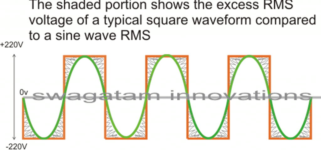
The image incorrectly shows 220V as the peak, actually it should be 330V
In the above diagram, the green colored waveform is the sine waveform, while the orange depicts the square waveform. The shaded portion is the excess RMS which needs to be leveled of in order to make both the RMS values as close as possible.
Converting a square wave inverter into a sine wave equivalent thus basically means allowing the square wave inverer to produce the required peak value of say 330V yet having an RMS just about equal to its sine wave counterpart.
How to Convert/Modify a Square Waveform to Sine Waveform Equivalent
This can be done either by carving a square wave sample into a sine wave form, or simply by chopping a sample square waveform into well calculated smaller pieces such that its RMS becomes very close to a standard mains AC RMS value.
For carving a square wave to a perfect sine wave, we can employ a wien bridge oscillator or more precisely a "bubba oscillator" and feed it to a sine wave processor stage. This method would be too complex and is therefore not a recommended idea for implementing an existing square wave inverter to a sine wave inverter.
The more feasible idea would be to chop the associated square wave at the base of the output devices to the required RMS degree.
One classic example is shown below:
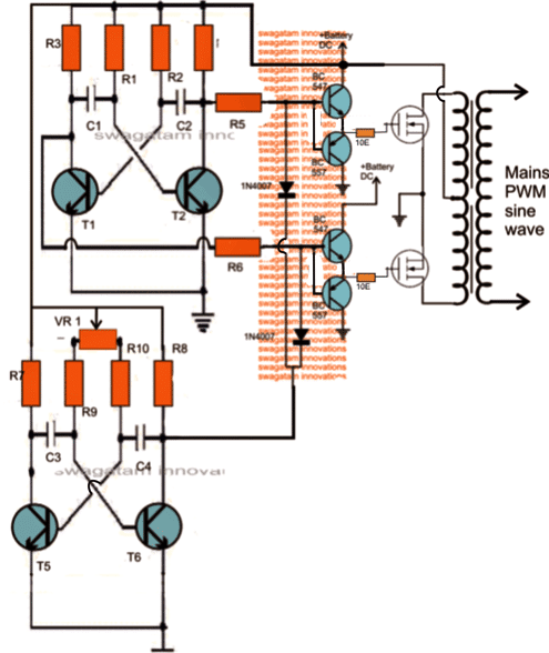
The first diagram shows an square wave inverter circuit. By adding a simple AMV chopper we can break down the pulses at the base of the relevant mosfets to the required degree.
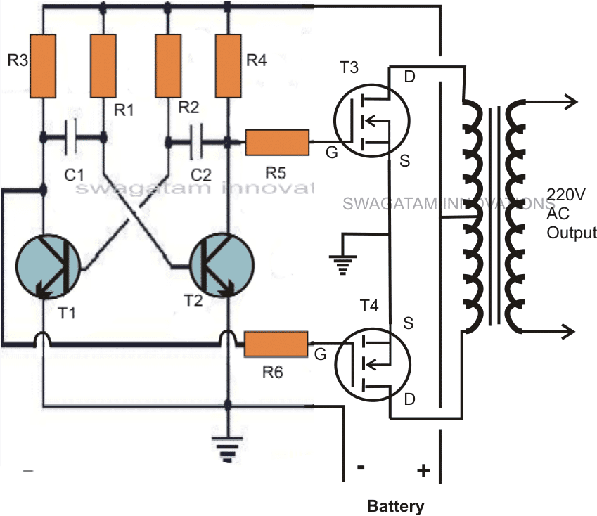
Modified square wave to sine wave equivalent inverter version of the above circuit.
Here the lower AMV generate pulses at high frequency whose mark/space ratio can be suitably altered with the help of preset VR1. This PWM controlled output is applied to the gates of the mosfets in order to tailor their conduction into the stipulated RMS value.
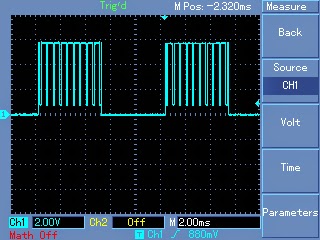
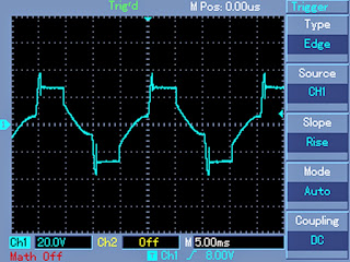
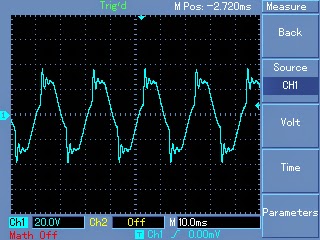
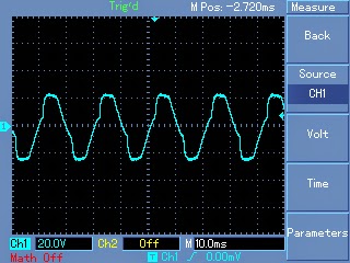
Expected typical waveform pattern from the above modification:
Waveform at the mosfet gates:
Waveform at the output of transformer:
Waveform after proper filtration using inductors and capacitors at the output of the transformer:
Parts List
R1, R2, = 27K,
R3, R4, R5, R6, R7,R8, R9, R10 = 1K Ohms,
C1,C2 = 0.47uF/100V metallized
C3, C4 = 0.1uF
T1, T2, T5, T6 = BC547,
T3, T4 = any 30V, 10amp mosfet, N-channel.
D1, D2 = 1N4148
VR1 = 47K preset
Transformer = 9-0-9V, 8 amp (specifications must be selected as per the output load for correct powre optimization)
Battery = 12V,10AH
Getting Better Efficiency Rate
The above explained conversion or modification will provide around 70% of efficiency with the achieved RMS matching. If you are interested in getting better and precise matching then probably a an IC 556 PWM waveform processor would be required.
You would want to refer to this article which shows the principle behind modifying a square waveform into a sine waveform using a couple of IC555.
The output from the above mentioned circuit can be similarly fed to the gate or the base of the relevant power devices which are present in the existing square inverter unit.
A more comprehensive approach may be witnessed in the this article where an IC 556 is used for extracting precise PWM based modified sine wave equivalents from a square wave sample source.
This waveform is integrated with the existing output devices for implementing the intended modifications.
The above examples teach us the simpler methods through which any existing ordinary square wave inverter may be modified into a sine wave inverter designs.
Converting into an SPWM
In the above article I have explained how the waveform of a square wave inverter could be optimized for getting a sine wave kind of waveform by chopping the square wave into smaller sections.
However a deeper analysis shows that unless the chopped waveform is not dimensioned in the form of SPWMs, achieving a proper sinewave equivalent may not be possible.
To satisfy this condition an SPWM converter circuit becomes essential for carving out the most ideal sinewaveform from the inverter.
The basic idea is to chop the output power devices with sine wave pulse width modulation, so that the power devices force the transformer winding to also oscillate in the SPWM mode and ultimately generate an optimized pure sine wave at the secondary side. The magnetic induction of the pulsed SPWM across the transformer winding finally gets the shape of a pure sine wave due to the inductive filtration of the transformer winding.
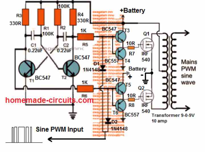
The following diagram shows how this could be effectively implemented with the concept discussed above.
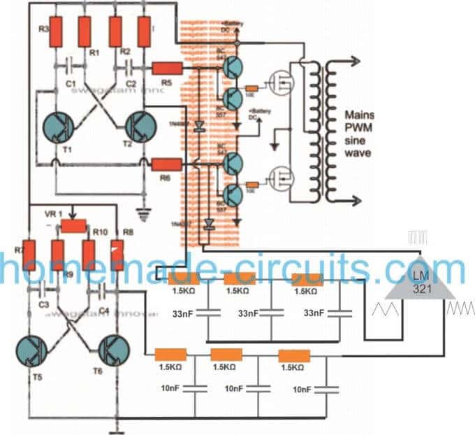
Through one of my earlier articles we understood how an opamp could be used for creating SPWMs, the same theory could be seen applied in the above concept. Two triangle wave generators are used here, one accepting the fast square wave from the lower astable, while the other accepting slow square waves from the upper astable and processing them into corresponding fast and slow triangle wave outputs, respectively.
These processed triangle wave are fed across the two inputs of an opamp, which finally converts them into SPWMs or sine wave pulse widths.
These SPWMs are used for chopping the signals at the gate of the mosfets which ultimately switch the waveform over the connected transformer winding for creating an exact replica of a pure sine waveform at the secondary side of the transformer through magnetic induction.
How to Calculate the Part Values
Astable Multivibrator Frequency (Square Waves):
Formula: f = 1 / (0.693 * (R1 + 2 * R2) * C)
For the fast square wave generator:
Let R1 = 10k ohms, R2 = 100k ohms, C = 10nF (example values).
ffast = 1 / (0.693 * (10000 + 2 * 100000) * 10e-9)
ffast = 1 / (0.693 * 210000 * 10e-9)
ffast = 68 Hz
For the slow square wave generator:
Let R1 = 10k ohms, R2 = 1M ohm, C = 100nF (example values).
fslow = 1 / (0.693 * (10000 + 2 * 1000000) * 100e-9)
fslow = 1 / (0.693 * 2010000 * 100e-9)
fslow = 7.1 Hz
RC Integrator Cutoff Frequency (Triangle Wave Generators):
Formula: fc = 1 / (2 * π * R * C)
For each RC stage assume R = 1.5k ohms and C = 33nF.
fcstage = 1 / (2 * 3.1416 * 1500 * 33e-9)
fcstage = 1 / (2 * 3.1416 * 0.0000495)
fcstage = 3223 Hz
For three stages the overall response rolls off steeply approximately at the same fcstage.
Op-Amp SPWM Generation:
The op-amp compares the fast triangle wave (carrier) and the slow triangle wave (modulating signal). The output is high when the carrier is greater than the modulating signal. This generates a sinusoidal PWM (SPWM).
Gate Drive Requirements for MOSFETs:
Formula: Ig = VSPWM / Rg
Assume VSPWM = 10V and Rg = 1.5k ohms.
Ig = 10 / 1500
Ig = 0.0067 A (6.7 mA)
This ensures the MOSFET switches efficiently.


Questions & Answers
I need a pure sine wave oscillator to drive my midget power stage of my inverter.
make the first circuit in this link:
https://www.homemade-circuits.com/2013/04/simple-pure-sine-wave-inverter-circuit.html
hellow swagatam, incase I add two more mosfet and connect them in parallel, in that case we will be having two mosfet in each side, Now how Will I Connect the chopper circuit on the mosfet? I have connected the gates with 1k resistor and sources with a thin wire of o.2 ohms. The inverter is working perfectly but i have a problem in connecting the choper circuit, please sir help
Hello hasan,
Don't connect the gate resistor common ends directly to the collector of T1/T2 rather connect them via another 1K resistor, now you can join the PWM diodes at the junction of these two 1K resistors,
Use 470 ohms instead of 1K that will be better.
Helo Sadi,
Yes you can employ the concept for modifying your existing square wave inverter.
RMS value would be simply the voltage that's specified at the output of your inverter without any load.
If it's 230V then adjust the preset until the output comes down to 230V….it's now set.
Hello Sadi,
Change the position of VR1, use two of them and connect in series with R9 and R10.
Adjust them carefully to get the required results
Dear Sir, I don't understand how to change the position of VR1
check the output 220V level while you adjust VR1, it will change in response to VR1, adjust until the output settles to the required level.
Will I obtain a very smooth sine wave and Can I run my desktop and laptop on this inverter using both circuits?.
The output will be modified sine wave not pure sine, but should be OK for PCs since all these gadgets have an AC to DC converters, so won't make any difference
Dear Sir Swagatam,
I am a fan of your blog and I've been inspired by your work.. for that i thank you very much.. how can i use ic 555 to joint with this circuit "sine wave inverter" to produce 220v at 60hz.. can you provide me a link… thank you very much sir.. and sorry for my bad english and where is D1 & D2 connected?
sorry i am new to electronics..
Thnx
Paul
Dear Paul
D1, D2 are connected the gates of the mosfets. please refer to the following post to learn more regarding your requirement.
https://www.homemade-circuits.com/2013/01/300-watts-pwm-controlled-pure-sine-wave.html
Good day… Pls can this design carry a 250watt device? If no, pls wat value of transformer and battery is appropriate? Thanks
yes it can carry 250 watts, you will simply need to upgrade the transformer and the battery upto that level.
Good day… Pls can this design carry a 250watt device? If no, pls wat value of transformer and battery is appropriate? Thanks
Will IRFZ44N, 5A transformer and 10AH battery b enough to carry a 250watts device for 12hours? If No, pls help me
Yes IRFZ44N will work, but the trafo should be rated at 9-0-9V/25amps and battery 12v/100ah
Pls can I use a JFET D500 in place of BC547??.
Pls can I use a JFET D500 in place of BC547??. And I have a 12-0-12v. Is it ok?
nope! it won't work
100AH will not support 1500 watts, you will need at least a 500AH battery.
Not more than 150 watts, at this much load the battery will last for 5 to 6 hours. You can use higher loads also but the battery would drain quickly.
Good day!
I would be able to help with a design using ordinary discrete components, as already i have presented plenty of such designs in this blog.
it may be due to lower rated transformer or battery or both, not the problem of inverter.
divide 400 by 12 or 9, you'll get the approximate current value.
I found an obscure article about how a Russian took a 330nF Capacitor, went across his 220v output MSW inverter signal, and was able to 'filter' the resultant into a 'near replica' of a PSW form. I don't have a scope to test this myself, have you ever tried to 'end filter' a MSW and scope it to see if you can 'filter' the wave a bit for a 'bubba sculpting session'? I may have misread him, that 330nF seemed awful small to work on that voltage, but you never know (probably was mu, not nano).
I have an elaborate article in my blog, which is actually being tried and updated regularly by a few dedicated readers. The last waveform image actually shows the effect of a cap across the output of the trafo which transforms the crude sine to a considerably refined sine wave….you may have a look at the various outcomes presented here:
https://www.homemade-circuits.com/2013/10/modified-sine-wave-inverter-circuit.html
Hello swagatam…. Please can u modify dis circuit to it regulates outputs to a steady voltage even on load like the one you posted in dis image. 4.bp.blogspot.com/-5GDTaart2mw/UmYX6r5TyzI/AAAAAAAAFiI/il_1gPepQVQ/s1600/inverter+output+voltage+correction+circuit.png
Hello Ifeanyi, i'll try to design it soon and post it.
I am so grateful, will be expecting it. I will love to take after you, you such an innovative engineer.
Hello swagatam, according to the design in this post and the one in the post in the link below. Which of the PWM diodes is correctly connected. Or it doesn't really matter how we connect it? 4.bp.blogspot.com/-4pFtMm0wuPQ/ULHioWwpZlI/AAAAAAAABnE/Q2UjJoTsFBU/s1600/Modified+sine+wave+inverter.png
Hello Ifeanyi, both are correct, the diode polarities are opposite because in the above article the driver devices are N-type while in this link it's P-type
That's true, I just noticed that. Thank U very much
Hello swagatam, if I power only the 555timer with 5v, will it have an adverse effect on the PWM?
Hello ifeanyi, the 555 output positive PWMs voltage should be equal to the mosfet 50Hz voltage, otherwise the PWM may not produce the correct effect. If the 50Hz IC is also driven with 5V then it would be fine.
I am not using a 50hz IC, I am just using a 50hz square wave oscillator using transistors and resistors as shown in the post above. Would it also be fine too to power the oscillator with 5,6,7 or even 12volts regualtor for a stable voltage.
The pwm peak voltage should match the gate voltage, that's the only criterion…
Since the gate voltage is usually the half of the supply voltage(12v), therefore the PWM peak voltage should be 6v. How can I ensure that I set the peak PWM to 6. What's the configuration
mosfet gate voltage (peak) will be always equal to the IC supply voltage which is being used for driving it. If the IC supply is 12V, the gate voltage will be also around 12V peak.
For voltage correction, can we connect the collector leg in the link below to the output of C4 to the diode? Will it work?
4.bp.blogspot.com/-5GDTaart2mw/UmYX6r5TyzI/AAAAAAAAFiI/il_1gPepQVQ/s1600/inverter+output+voltage+correction+circuit.png
yes that would work….
Am afraid this won't work, because the circuit diagram of the voltage correction you have doesn't have a transformer, hence the voltage is just rectified to abt 200VDC which could damage the mosfet which accepts 55v. I think we should use a smaller TRF to step down to b safe.
the transistor shown in the voltage correction diagram will ground the inverter shutdown pin to which its connected for implementing the regulation, it will not supply any high voltage to the circuit with which is connected…
I have got d squarewave side working, bt wen I connected the pwm, the voltage drops to zero. What shud I do now
you will need to adjust VR1 correctly for getting optimum results and the trafo voltage rating shpuld be selected as 30% to 40% less than the batt voltage.
I used an 8-0-8v transformer, I used a 12v battery and I get 350v AC, bt wen I connect the diode from the 2nd circuit(PWM), the voltage drops to zero, I also turn the 47k pot trim but iget no results.
change the 47k pot with a higher value pot, example you can try a 220k, 470k or even 1M pot, this will allow you to select from a wide range of PWMs.
adjust it to get around 220V at the output
Give me a name of software in which we can draw a circuit of inverter and simulate it with ic 4047..
mail: vimaljogiya007@gmail.com
plz help me in project… I i take a project of inverter
sorry i have no idea about it.
LTspice could do it .. (Linear Technology).