In this post I have explained about a few easy to build, compact 1 watt LED bulb circuits. The first circuit is SMPS based, the second design uses a capacitive power supply, while the remaining concepts show how to used a DC source to illuminate a 1 watt LED.
Warning: Many of the circuits I have explained below are not isolated from mains AC, and therefore are extremely dangerous to touch in the powered and open condition. You should be extremely careful while building and testing these circuits, and make sure to take the necessary safety precautions. The author cannot be held responsible for any mishap due to any negligence by the user
1) Small 1 watt SMPS LED Driver
In the first design which is the most recommended one, we study an SMPS LED driver circuit which can be used for driving high watt LEDs rated anywhere between 1 watt LED upto 12 watts. It can be directly driven from any domestic 220V AC or 120V AC mains outlets.
Introduction
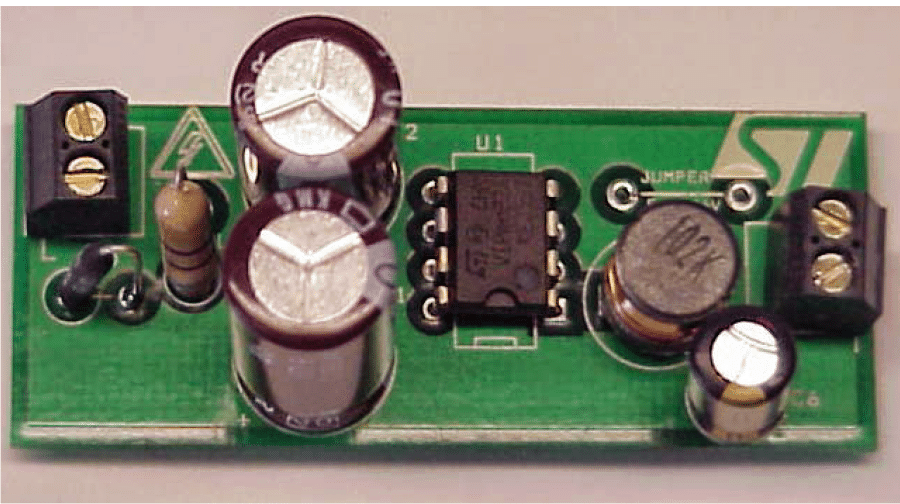
The first design explains a small non isolated SMPS buck converter design (non-isolated Point of Loads), which is very accurate, safe and easy to build circuit. I have explained the details.
You may also want to learn How to Design LED Driver Circuits
Main Features
The proposed smps LED driver circuit is extremely versatile and specifically suited for driving high watt LEDs.
However being a non-isolated topology does not provide safety from electric shocks at the LED side of the circuit.
Apart from the above drawback, the circuit is flawless and is virtually protected from all possible mains surge related dangers.
Although a non-isolated configuration may look a bit undesirable, it relieves the constructor from winding complex primary/secondary sections on E-cores, since the transformer here is replaced with a couple of simple ferrite drum type of chokes.
The main component here responsible for the execution of all the features is the IC VIPer22A from ST microelectronics, which has been specifically designed for such small transformerless compact 1 watt LED driver applications.
Circuit Diagram
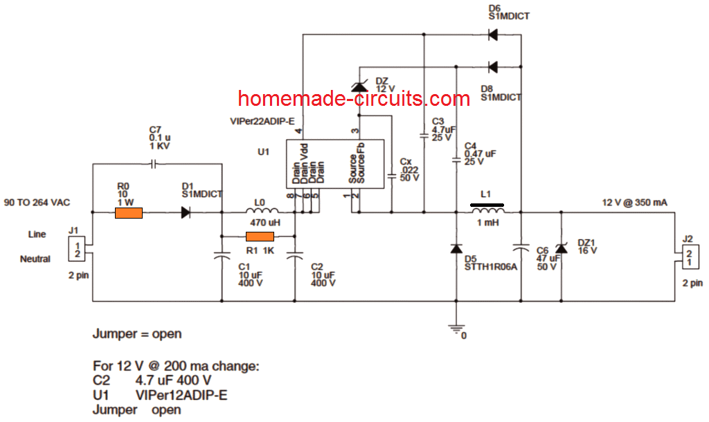
Image Courtesy: © STMicroelectronics - All rights reserved
Circuit Operation
The circuit functioning of this 1 watt to 12 watt LED driver can be understood as given under:
The input mains 220V or 120V AC is half wave rectified by D1 and C1.
C1 along with the inductor L0 and C2 constitute a pie filter network for cancelling EMI disturbances.
D1 should be preferably replaced with two diodes in series for sustaining the 2kv spikes bursts generated by C1 and C2.
R10 ensures some level of surge protection and acts like a fuse during catastrophic situations.
As can be seen in the above circuit diagram, the voltage across C2 is applied to the internal mosfet drain of the IC at pin5 to pin8.
An inbuilt constant current source of the VIPer IC delivers a 1mA current to pin4 of the IC which is also the Vdd pin of the IC.
At about 14.5V at Vdd, the current sources gets switched OFF and forces the IC circuitry into an oscillatory mode or initiates pulsing of the IC.
The components Dz, C4 and D8 become the circuit regulation network, where D8 charges C4 to the peak voltage in the freewheeling period and when D5 is forward biased.
During the above actions, the source or the reference of the IC is set to about 1V below ground.
For a comprehensive info about the circuit details of the 1 watt to 12 watt LED driver, please go through the following pdf datasheet by ST microelectronics.
2) Using Transformerless Capacitive Power Supply
The next 1 watt LED driver I have explained below shows how to build a few simple 220 V or 110 V operated 1 watt LED driver circuit,that would cost you not more 1/2 a dollar, excluding the LED of course.
I have already discussed capacitive type of power supply in a couple posts, like in LED tube light circuit and in a transformerless power supply circuit, the present circuit also utilizes the same concept for driving the proposed 1 watt LED.
Circuit Operation
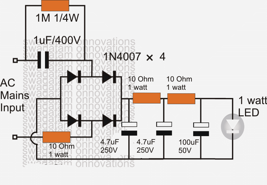
In the circuit diagram we see a very simple capacitive power supply circuit for driving a 1 watt LED, which may be understood with the following points.
The 1uF/400V capacitor at the input forms the heart of the circuit and functions as the main current limiter component of the circuit. The current limiting function makes sure that the voltage applied to the LED never exceeds the required safe level.
However high voltage capacitors have one serious issue, these do not restrict or are not able to inhibit the initial switch ON mains power in rush, which can be fatal for any electronic circuit LEDs are no exceptions.
Adding a 56 Ohm resistor at the input helps to introduce some damage control measures, but still it alone cannot do the complete safeguarding of the involved electronics.
An MOV would certainly do, also what about a thermistor? Yep, a thermistor would also be a welcome proposition.
But these are relatively at the costlier side and we are discussing a cheap version for the proposed design, so we would want to exclude anything that would cross a dollar mark as far as the total cost goes.
So I thought of an innovative way of replacing an MOV with an ordinary, cheap alternative.
What is the function of an MOV
It's to sink the initial burst of high voltage/current to ground such that it is ground before reaching the LED in this case.
Wouldn't a high voltage capacitor do the same function if connected across the LED itself. Yes it would surely operate the same way as an MOV.
The figure shows the insertion of another high voltage capacitor directly across the LED, which sucks the instantaneous influx of voltage surge during power switch ON, it does this while charging up and thus sinks almost the entire initial voltage in rush making all the doubts associated with a capacitive type of power supply distinctly clear.
The end result as shown in the figure is a clean, safe, simple and a low cost 1 watt LED driver circuit, which can be built right at home by any eletronic hobbyist and used for personal pleasures and utility.
CAUTION: THE CIRCUIT SHOWN BELOW IS NOT ISOLATED FROM THE AC MAINS, THEREFORE IS EXTREMELY DANGEROUS TO TOUCH IN POWERED POSITION.
Circuit Diagram
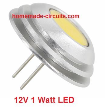
NOTE: The LED in the above diagram is a 12V 1 watt as shown below:
In the above shown simple 1 watt led driver circuit, the two 4.7uF/250 capacitors along with the 10 ohm resistors form a kind of "speed breaker" in the circuit, this approach helps to arrest the initial switch ON surge inrush which in turn helps to safeguard the LED from getting damaged.
This feature can be replaced with an NTC which are popular for their surge suppressing features.
This enhanced way of tackling the initial surge inrush problem could be by connecting an NTC thermistor in series with the circuit or the load.
Please check out the following link for knowing how to incorporate an NTC thermister in the proposed 1 watt LED driver circuit
The above circuit can be modified in the following manner, however the light may be a little compromised.
A good way of tackling the initial surge inrush problem is by connecting an NTC thermistor in series with the circuit or the load.
Please check out the following link for knowing how to incorporate an NTC thermister in the proposed 1 watt LED driver circuit
https://www.homemade-circuits.com/2013/02/using-ntc-resistor-as-surge-suppressor.html
3) A Stabilized 1 watt LED Driver using Capacitive Power Supply
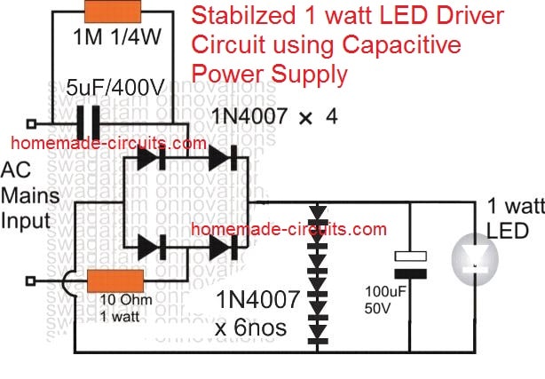
As can be seen, 6nos of 1N4007 diodes are used across the output, in their forward biased mode. Since each diode would produce a drop of 0.6V across itself, 6 diodes would create a total drop of 3.6V, which is just the right amount of voltage for the LED.
This also means that the diodes would shunt the rest of the power from the source tp ground, and thus keep the supply for the LED perfectly stabilized and safe.
Another Stabilized 1 watt Capacitive Driver Circuit
The following MOSFET controlled design is probably the best universal LED driver circuit that guarantees a 100% protection for the LED from all types of hazardous situations, such as sudden over voltage and over current or surge current.
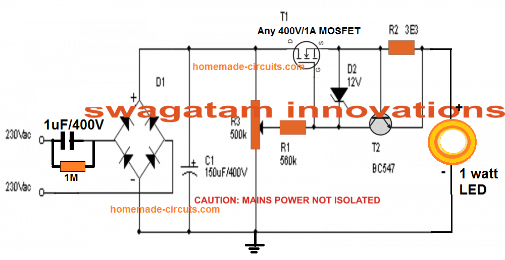
A 1 watt LED connected with the above circuit would be able to produce around 60 Lumens of light intensity, equivalent to a 5 watt incandescent lamp.
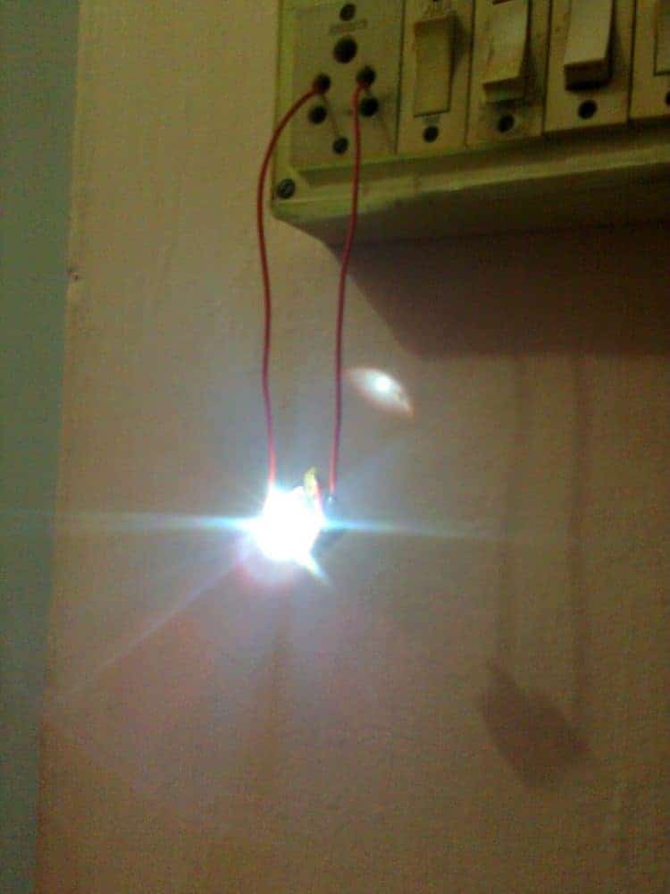
Prototype Images

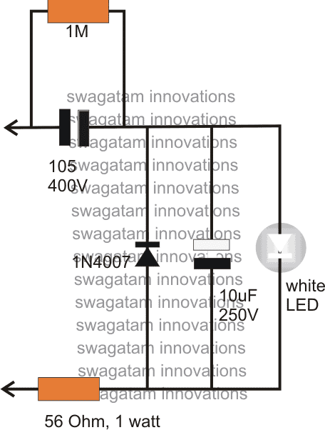
The above circuit can be modified in the following manner, however the light may be a little compromised.
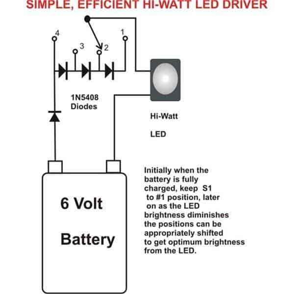
4) 1 Watt LED Driver Circuit Using a 6V Battery
As can be seen in the fourth diagram, the concept hardly utilizes any circuit or rather does not incorporate any hi-end active component for the required implementation of driving a 1 watt LED.
The only active devices that's been employed in the proposed simplest 1 watt LED driver circuit are a few diodes and a mechanical switch.
The initial 6 volts from a charged battery is dropped to the required 3.5 volts limit by keeping all the diodes in series or in the path of the LED supply voltage.
Since each diode drops 0.6 volts across it, all four together allow only 3.5 volts to reach the LED, lighting it safely, yet brightly.
As the illumination of the LED drops, each diode is bypassed subsequently using the switch, to restore the brightness of the LED.
The use of the diodes for dropping the voltage level across the LEDs makes sure that the procedure does not dissipate any heat and therefore becomes very efficient in comparison to a resistor, which would have otherwise dissipated a lot of heat in the process.
5) Illuminate 1 Watt LED with a 1.5V AAA Cell
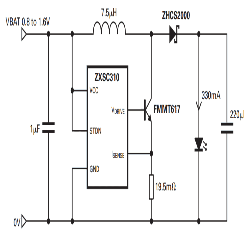
In the 5th design I have explained how to illuminate a 1 watt LED using a 1.5 AAA cell for a reasonable amount of time.The circuit is obviously based on boost driver technology, other wise driving such a huge load w such minimal source is beyond imagination.
A 1 watt LED is relatively huge when compared to a 1.5 V AAA cell source.
A 1 watt LED needs minimum 3 volts supply which is double the above cell rating.
Secondly a 1 watt LED would require anywhere between 20 to 350 mA of current for operating, 100 mA being a respectable current for driving these light machines.
Therefore using a AAA penlight cell for the above operation looks very remote and out of question.
However the discussed circuit here proves all of us wrong and successfully drives a 1 watt LED without much complications.
THANKS TO ZETEX, for providing us with this wonderful little IC ZXSC310, which requires just a few ordinary passive components for making this feat possible.
Circuit Operation
The diagram shows a rather simple configuration, which is basically a boost converter set up.
The input DC of 1.5 volts is processed by the IC to generate a high frequency output.
The frequency is switched by the transistor and the schottky diode via the inductor.
The rapid switching of the inductor provides the required boost in the voltage which becomes just appropriate for driving the connected 1 watt LED.
Here, during the completion of each frequency, the equivalent stored energy inside the inductor is pumped back into the LED generating the required voltage boost, which keeps the LED illuminated for long hours even with a source that's as small as a 1.5 volt cell.
Prototype image

1 Watt Solar LED Driver
This is school exhibition project which can be used by children to show how solar energy can be used for illuminating a 1 watt LED.
The idea was requested by Mr. Ganesh, as given below:
Hi Swagatam, I have come across your site and find your work very inspiring. I am currently working on a Science, Technology, Engineering and Math (STEM) program for year 4-5 students in Australia. The project focuses on increasing children’s curiosity about science and how it connects to real-world applications.
The program also introduces empathy in the engineering design process where young learners are introduced to a real project (context) and engages with their fellow school peers to solve a worldly problem. For the next three years, our focus is on introducing children to the science behind electricity and the real-world application of electrical engineering. An introduction to how engineers solve real-world problems for the greater good of society.
I am currently working on online content for the program, which will focus on young learners(Grade 4-6) learning the basics of electricity, in particular, renewable energy, i.e. solar in this instance. Through a self-directed learning program, children learn and explore about electricity and energy, as they are introduced to a real-world project, i.e. providing lighting to children sheltered in the refugee camps around the world. On completion of a five-week program, children are grouped in teams to construct solar lights, which are then sent to the disadvantaged children around the world.As a not 4 profit educational foundation we are seeking your assistance to layout a simple circuit diagram, which could be used for the construction of a 1 watt solar light as practical activity in class. We have also procured 800 solar light kits from a manufacturer, which the children will assemble, however, we need someone to simplify the circuit diagram of these light kits, which will be used for simple lessons on electricity, circuits, and calculation of power, volts, current and conversion of solar energy to electrical energy.
I look forward to hearing from you and keep on with your inspiring work.
The Circuit Design
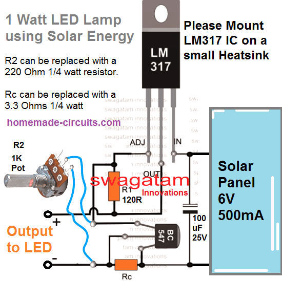
Whenever a simple yet safe solar controller is required we inevitably go for the ubiquitous IC LM317. Here too, we use the same inexpensive device for implementing the proposed 1 watt LED lamp using a solar panel.
The complete circuit design can be seen below:
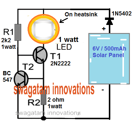
A quick inspection reveals that if a current control is present, voltage regulation can be ignored. Here's a simplified version for the above concept, using only a current limiter circuit.


Questions & Answers
CFL bubs are very complicated to build because they involve inductors which are too critical…so i am sorry, no ideas.
Hello Swagatam!
Thank you for all of your time answering everyone's questions. I would like to use your circuit design in a middle school project to create LED light fixtures housed in home cut and planed cherry wood housings. I am wondering which of your two posted designs you would recommend for this project, and how many 1 watt LED's you think would be appropriate for a 3 foot long bar type fixture to give an impression of consistent lighting when used as uplighting mounted above eye level on a wall (I am imaging a simple V design for the housing).
Thank You!
Hello Shaun,
34nos 1 watt LEDs would be enough within a 3ft span. Remember that you will need a heatsink back PCB for mounting the LEds and an additional thick aluminum heatsink attached behind the PCB for optimum cooling.
Along with this you will have to incorporate a current limiter circuit with each LED module, and the the whole thing will need to be powered through a 2amp 12V smps.
For wiring details and calculations you may refer to the following post:
https://www.homemade-circuits.com/2013/02/make-this-1000-watt-led-flood-light.html
Dear Sir, i am no expert like you..
i want to try build a led driver.
the DC output should be
14 Ampere (60 * 700mA) , 168 volt (2,8 * 60) , 60 Watt (60 pc * 1 W)
since i want use 1 W led, DC2.3-2.8V 700mA each (read it on the spec of the bulb)..
i want to use 60 piece bulb of 1w power led.
is the DC out that i calculate is right or wrong ?
Dear Andre,
You can use the circuit which is given in the above article, by connecting all the LEds in series to the output. Be sure to connect a thermistor in series with the input of the above transformerless power supply and increase the input capacitor value to 5uF/400V non-polar
Your current calculation needs correction…..when LEDs are connected in series the current gets shared, meaning in your case the current would be just 700mA…..
By the way 1 watt LEDs are rated at 350mA not 700mA, I am doubtful about your specs.
Sir
when i have made this circuit i got only 2.82 volt on each 1 Watt led.. so pls help me how to increase volt to 3.3V…
I have used following items…
1. 105K/400volt capacitor
2. 150 or 570K resistance for cap
3. 4 diode 4007
4. 56 ohm resistance 2 watt
5. 100V/100mf condenser
6. 1watt 3LED in series
Hi Vivek,
Increasing current won't be a good idea and is not recommended for such power supplies, instead you can use ordinary 5mm LEDs and connect 50 of them in series, it will produce much higher illumination than a three 1 watt LEDs.
hi!
when I made the above ckt the resistor 56 ohms just gets blows and if it doesn't, the LED lights up but with very low brightness
please make this circuit:
2.bp.blogspot.com/-nKF8T8lKIxY/UMg7YDLNQ3I/AAAAAAAAB8U/S1OWTK0cMD4/s1600/Surge%20free%20transformerless%201%20watt%20LED%20driver%20circuit.png
Use 6 diodes and not 12, if you are connecting 1 LEd only
The above power supply will not be able to illuminate 1 watt LEDs even after suitable changes.
…i mean it won't drive with full illumination, anyway you can try connecting the LEDs in series with the above circuit and see the results.
Can you please provide me any link, or provide me some hint to understand how did you arrive at the input side capacitor of 1uF/400V? I mean how does this value of capacitor restrict or limit the current that is being used by power-led? Also how are we restricting the voltage supplied to the led to 3.4V. I know that even if we provide 5V to the led the forward drop will always be 3.4V; but still if we provide a higher voltage maybe something like 200Vdc then I believe the led will burn out. Then how do we limit the voltage supplied to the led?
The current is important here which we want to limit by putting a resistance in series with the mains, the capacitor acts like a resistance here which is calculated by calculating its reactance, you can Google a little to find the formula for reactance, this will be in Ohms, next you can employ Ohms law to calculate the current that can be limited through this reactance or resistance.
The voltage gets automatically restricted to load voltage only in case the current is considerably lower than the maximum spec of the load (LED here), since a 1uF/400V can allow a max of 70mA which is far less than the 1watt LEDs 350mA, the voltage settles down to the LED FWD V level
If it's 20mm type then yes you can use it with full capacity
……sorry i meant 20mA
Hi, What is your driver voltage?
You will need to put appropriately calculated resistors with each ED, only then all will light up with uniform brightness.
Hi output voltage of about 3 volts. Is it possible to add., And because the filter capacitor should be 250 volts.
dear mr.Swagatam,
i need transformerless LED driver for 3Watt LED
Hi sir I'm planing to connect 40 1 watt led's in series so i want to add an fan speed controller for dimming. I'm interested in electronic but i don have much knowledge in electronic plese help me can u send me the pic of ready circuit for reference wajedpasha58@gmail I'm waiting for Ur reply
Hi Wajed,
please refer to the last diagram in this article, you can try this for your project:
https://www.homemade-circuits.com/2012/11/using-fan-dimmer-for-controlling-led.html
Dear Muhammad,
You will have to measure the volts across the leads of the LED, and measure current in series with the LED, then multiply the results to get the wattage.
which type of capacitor used at input & output stage for above circuit please tell. as early as possible
input is metallized polyester, and output can be a metallized polyester or an electrolytic
how to lighten up 20 LED of one watt each connected in parallel , n how many voltage require i have a 35voltage DC battery and how to control upcoming voltage from battery to glow much brighter
with 35V you get an opportunity to connect 10 LEDs in series with a single limiting resistor, so with 20 LEDs you can make two such strings and connect them in parallel.
The resistor value will be 6 Ohm 1 watt for each string.
The above set up will produce the most optimal response from the LEDs
is there any circuit to glow 10w single chip led from 230v main?
an smps is the only solution, no other easier method.
Can i use J3305 transistor sir?
Hello Sir,
I have seen your posting of 1watt led drive from mains supply its good i have tried but,
my led has blown out and i have checked the out put is showing 320v Dc..
I have used the the below parts..
1) 1N4007
2) Resistor 1mego ohm 1/4watts
3) Resistor 56ohms 1watt..
4) capacitor 105/400v polyster type.
5) Capacitor 104/250v polyster type.
6) LED 1watt white.
I have connected as per the draw shown above kinldy le me know where im doing the mistake..
mains voltage i have given 240volts to the above circuit..
Kindly help me sir…
Hanumanth
replace 104/250 with 10uF/250V, or alternatively you can add an NTC as suggested in the following article.
https://www.homemade-circuits.com/2013/02/using-ntc-resistor-as-surge-suppressor.html
Hello I like your post very much keep it up!!!
Can I connect about 50 ,5mm leds to this circuit without big 1W leds??
hi thanks!
yes you can connect them…put them all in series.
use 474/400V instead of 105/400V
Bro how can i drive multicolor 3/4 LED by 220v through resistance only? it will be used as night lamp.
use a 2k/20 watt resistor
Hi, Can you guide me with making of LED Street light using 30 Nos. 1W SMD LEDs connected in 3 rows in parallel with 10 LED's in Series. I will use available ready-made good LED Driver (pls give spec of Driver required). Thanx
Hi You'll need a 33V, 350mA SMPS driver circuit, preferably a current controlled type, if it's not current controlled you could employ the first design from the following link, in conjunction with it.
https://www.homemade-circuits.com/2013/06/universal-high-watt-led-current-limiter.html
Hi Sir,
What is the output voltage and current of the circuit?
Thanks,
Naresh.S
Hi Naresh, It would settle down to the 100uF capacitor voltage rating without load. and when a load is connected such as an LED it would further come down to 3.3V
PLEASE help me i need 12-17 voltage circuit and minimum 0.5 ampere current and i only want to use maximum of 2 reistance and two capacitor and one bridge rectifire like in the circuit i mentioned in link.I just want to know the value of resistance and capacitance for my purpose
cdn.instructables.com/FZG/3MTW/G3KY0MRL/FZG3MTWG3KY0MRL.LARGE.jpg
Sorry that's not possible, you will have to include a transistor stage also for reliability and safety because at 0.5amps the initial surge will be too high which could damage the load instantly.
hai sir,
i am aravind
while i am surfing through internet i found that 1uf cap will provide 40ma.
then how it glows 1 watt led which requires 300ma.
does 40ma amp is enough?
please explain.
Hi Aravind, 1uF will produce 70mA not 40mA, but anyway the LEDs will not get 300mA from it and will light up with 70mA brightness only.
dear sir,
Can i replace 1uf/400V by 220nF/400V or 1uf/250V
1uF/250V can be tried
sir shall i use 105k/250v instead of 1uf /400v?
It can be used but it won't be reliable….
hello,
Can you suggest a circuit to reduce the flickering of LED which is powered by energy generated from a small turbine rotated by water.approx voltage across LED is 1.6v
just connect a 100uF/25V capacitor directly across the LED leads.
Hi Swagatam, i like your blog. i have question related changing "2pcs of 4,7uf/250v and 2 pcs of 10 ohm/1watt with 1 pcs of NTC. what value of NTC of it? is it 20 ohm?