In this post I have explained how to build a simple yet accurate timer circuit using the IC 4060 and some ordinary passive components.
Main Advantage of using IC 4060 as the Timer IC
I have already discussed this IC comprehensively in one of my previous articles, everything regarding its pin outs have been discussed there in detail. We studied that the IC 4060 is specifically suited for timer applications and also as an oscillator. In this article we’ll study how a simple versatile timer can be built using the IC 4060.
Other than the IC you would require just a couple of resistors, one pot and a capacitor for making this timer.
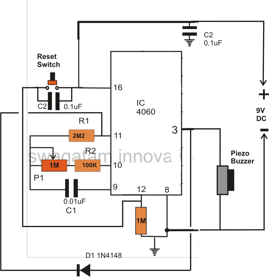
Referring the figure, the simplicity of the design becomes evident and therefore this circuit is perfectly suited for all electronic newcomers, who can easily build this project and enjoy its useful service.
As explained earlier in one my articles, the IC has an in built oscillator that needs just a few passive external components for making it tick.
Depending upon the values of the external RC components, the oscillation periods can be varied right from a few fractions of a second to many hours.
RC components refer to the values of the external time determining components consisting of a resistor or a pot and a capacitor.
The outputs produce a varied rate of time periods; each output generates time periods that’s exactly double to that of the previous output in a certain order of the IC pin outs.
Since here we want to use this unit as a timer we have selected the pinout which is last in the order as far the length of the time period is concerned, meaning we have selected pin #3 which generates the highest delay period.
The biggest advantage of making a timer using IC 4060 is that the involved timing capacitor can be kept as small as possible by increasing the complementary timing component value, which is the resistor.
This helps to keep the circuit simple, smaller and very sleek, unlike other timer IC like 555 which require high value electrolytic capacitors for generating even ordinary time delays.
How the Circuit is Latched when Time is Elapsed
In the figure you can see a diode being introduced from the output pin #3 to one of the oscillator pin #11. This diode acts as a latching component, which latches the IC once the set time lapses and the output of the IC goes high.
If this diode is not inserted, the output would go freewheeling from logic high to logic low and keep repeating the time delays.
The circuit may be powered from a small 9 volt battery which will last almost for ever.
A buzzer is fitted at the output for the required indications of the timer output after the time delay has elapsed.
How to Reset the Timer
The IC may be reset simply by pressing the reset button or alternatively the circuit gets automatically reset when switched off and powered again.
How to Calculate Frequency or Time Delay of IC 4060 - The Formula
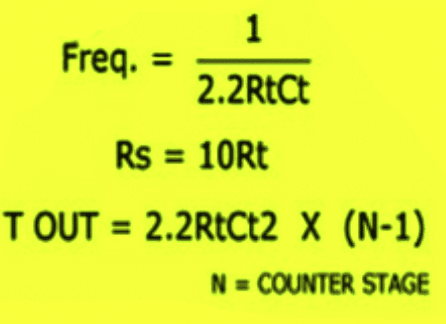
Or Alternatively the following standard formula for calculating the Rt and Ct values is:
f(osc) = 1 / 2.3 x Rt x Ct
2.3 is a constant as per the ICs internal configuration.
Rt will in Ohms and Rt in Farads
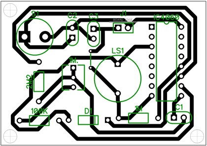
PCB Design
Adding a Relay
You can further upgrade the above design by adding a relay control to the output in order to facilitate an external mains AC load switching, as shown in the following image:
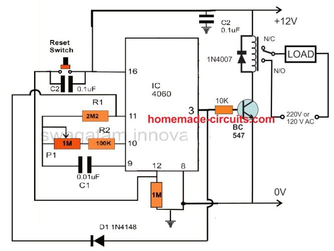
Remember the delay interval at pin3 can be increased by increasing the C1 value along with the P1 pot value. However, make sure that the C1 is always a non-polar, hence to increase its value you can connect many number non polar capacitors in parallel. For example you can connect non-polar 1uF capacitor as many numbers as you want for getting a desired long delay.
Delay OFF Timer (1 to 2 hours)
The IC 4060 can be also configured as a simple delay off timer with a delay of 1 to 2 hours or more.
A delay OFF timer basically switches ON the load initially, when the timer is switched ON, and then turns it off when the delay period lapses.
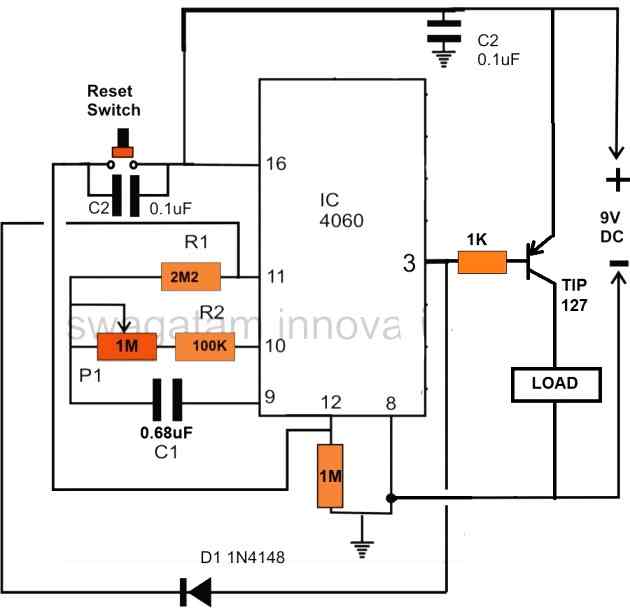
The circuit does not use a relay, instead powers the load directly through a PNP power transistor. However, if you want to include a relay, you can replace the TIP127 transistor with a BC557, and replace the "LOAD" with a relay. Don't forget to connect a freewheeling diode across the relay coil.
Note that here a PNP transistor is used for switching the load, this is done to implement the delay OFF function of the circuit. If a delay ON function is required, then the PNP transistor must be replaced with an NPN transistor.
Test Results for the above 4060 Relay based Timer Circuit
We would like to extend our deepest gratitude to Mr. Val for his exceptional expertise, unwavering dedication, and invaluable contributions to the development of our IC 4060 based timer circuit. Through his extensive knowledge and meticulous efforts, Mr. Val has not only modified and tested the circuit but also provided us with comprehensive documentation, including images and circuit diagrams, as given below.
Specifications:
- RELAY ON WHEN SWITHCED ON
- DELAYED OFF TIME WITH POT SETTING
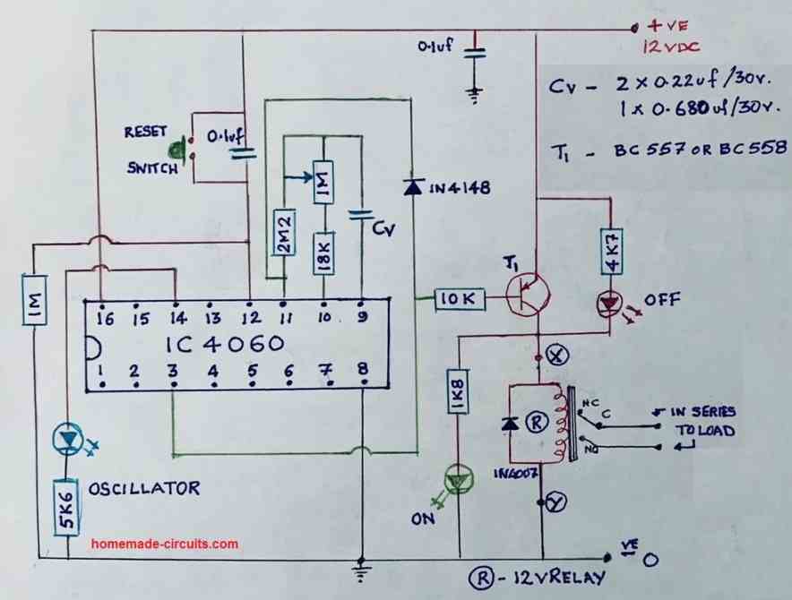
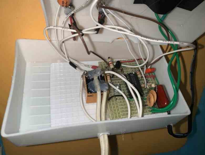
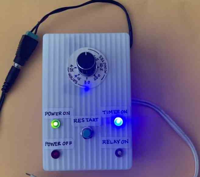
With great precision and attention to detail, Mr. Val meticulously tested the modified circuit, ensuring its flawless performance. His commitment to excellence and thoroughness in assessing every aspect of the design greatly impressed us. Through his unwavering efforts, we gained confidence in the reliability and efficiency of our timer circuit.
Understanding the Basic ON/OFF sequence of IC 4060 pinouts
The following video shows how a basic timer circuit may be configured using an IC 4060 and a few supporting passive components.
The schematic for the circuit discussed in the video can be visualized in the following diagrams:
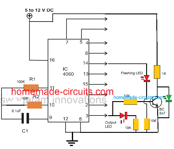
The following image shows how to latch IC 4060 output by adding a diode across the selected output pin and pin#11
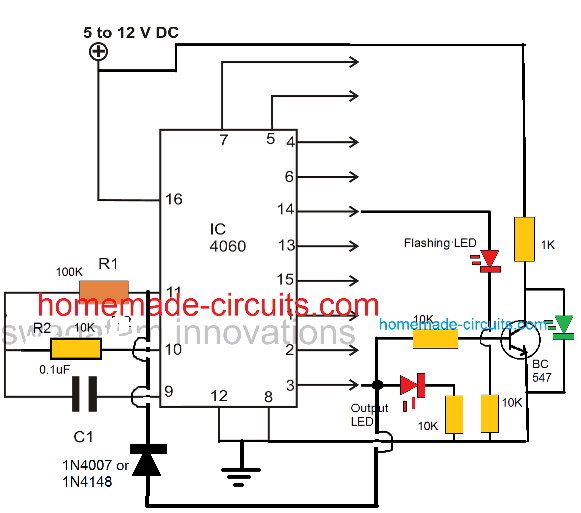
As we already know that the timing output or delay across all the shown output pins of the IC 4060 depends on the product of the values of R1 and C1, here pin#3 can be seen going after 32 logic pulses from pin#14 of the IC. Meaning when the LED at pin#14 completes 32 pulses, the LED at pin#3 switches ON, and switches OFF after another 32 pulses from pin#14. Identically you may find different equivalent rates at the other output pins of the IC.
This timing proportion is observed when R2 and C1 are selected to be 10K and 0.1uF respectively.
Simple Timer with Alarm
The next circuit is also designed using the CMOS IC CD4060, that includes a pulse generator and a counter. When power is switched on via S1, a reset voltage is given to the IC through C2. Simultaneously the IC built-in oscillator starts providing pulses to the counter.
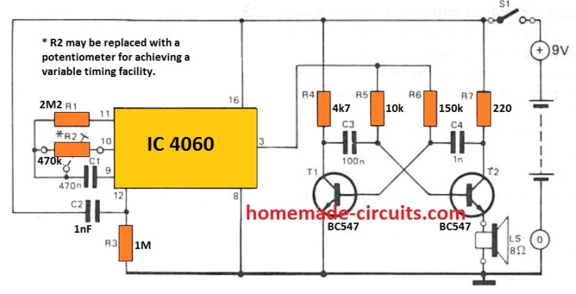
Following 213 clocks, the counter output (Q14) goes high, turning on the oscillator across T1 and T2. By doing this a sharp 3 kHz frequency that is emitted through an 8 ohm small loudspeaker. The circuit is powered down simply by turning off S1.
With the indicated R2 and C1, the buzzer will sound approximately An hour after the circuit has been started up. By upgrading R2 with a 1 M adjustable potentiometer, the buzzer time period could be varied from 5 minutes to 214 hours.
The potentiometer scale may be appropriately calibrated for quick setting up. The circuit utilizes hardly any current (0. 2 mA although the counter will be operating with 35 mA when the alarm signal is turned on) thus that a 9 V battery should promise quite an extended life.
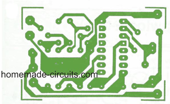
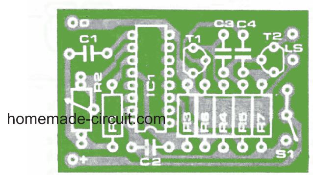
PCB Design and Component Layout for the above timer with alarm can be seen below:


Questions & Answers
Hi swagatam! Can you design me a circuit with the folllowing question?
“Design a circuit that displays the last 2 digit of your birthdate using IC7447 and Common cathode display “.
and an another request please make this simple with easily available components!
thankyou!
Good day Engr, I want to build a timer circuit with cd4060 to power a system 30 seconds ON and 10 seconds OFF. The system will repeat like that indefinitely until power is out. what modifications do I have to do. I want use variable resistors to preset the desired time intervals.
Moses, it is difficult to adjust a 4060 based timer with different ON/OFF timings, unless two of them are used, as discussed in the following post:
https://www.homemade-circuits.com/how-to-make-simple-programmable-timer/
Or you can also try a 4060 and 4017 based design for the same:
https://www.homemade-circuits.com/how-to-make-long-duration-timer-circuit/
THANK YOU SO MUCH SIR. PLEASE HOW CAN I ACHIEVE THE SAME THING WITH TWO NE555 TIMER ICs IN MONO STABLE MODE WHERE THE END OF TIMING OF ONE WILL TRIGGER THE START OF THE OTHER. I WANT TO TRY IT AS WELL.
Moses, I tried but cannot figure out how to design programmable timers using cascaded 555 ICs, I will keep trying though and let you know if there’s any luck..
Hi Jai,
You can get all the required information from the following post:
https://www.electronics-tutorials.ws/counter/7-segment-display.html
merhaba bu entegre ile 6 saatlik bir zamanlama için gereken direnç kondansatör değerleri nelerdir?
Hi, you can use the given formula, replace the f(osc) with 0.00002314814
sir I am referring the circuit that you showed in your video with out a diode
Ok, if you do not want to show the green LED response or if you do not wish to use a relay or any external load, then you can eliminate the BC547 transistor, it won’t be required…
please also tell me that polarized capacitor can be used or it is necessary for the proper functioning of the circuit to use a non polarized capacitor
if I only change resistor to a higher value time will change?
The timing capacitor at pin#9 must be strictly a non-polarized capacitor.
You can either change the resistor at pin#10, or the capacitor at pin#9 or both to vary the output time delay.
does BC 547 transistor is necessary for the working of the circuit or I can ignore initially to make simpler circuit
Arham, which circuit diagram are you referring to exactly?
sir I wanted to increase the off time but wants to keep the on time to 32 flashes please guide me how
Hi Arham, for 32 count we will have to add two 4017 ICs with the 4060 IC. Let me know if it is ok with you?
PLEASE CAN THIS FLASHING LEAD BE MADE TO REMAIN HIGH WITH FLASHING WHEN THE LOAD IS SWICHED ON
No that may not be possible, it will do the opposite.
Hi, i understand im very late to this webpage… but i need to design a circuit which has a potentiometer variable from 0minutes – 60minutes, that when the time has elapsed a buzzer and led goes off, also has a reset. Any help would be much appreciated. Thanks. @jacktroygreen@hotmail.co.uk
Hi, I think the hand drawn circuit design with the prototype images is the one which exactly matches your requirement. You can try that. For 60 minutes delay you may have to use a 5uf capacitor at pin9 of the ic, which must be non-polar, not a polarized one.
is there a way in which i could connect the circuit up to a dial knob so that i could change how long, 0-60min, externally it takes before alarm elapses?
You can connect a knob to the 1M potentiometer and calibrate it with the specific time intervals.
The calibration might need some practical trial and error method.
Also is the circuit able to be battery powered?
Yes, you can use a battery with a voltage matching the relay coil voltage.
Thanks very much. Just realised in the circuit there is no buzzer, where would i be able to addone in so that when the timer elapses the buzzer goes off? Thanks somuch for your help
No problem…You can connect the buzzer parallel to the relay coil.
Hi, still working with this circuit. Would you be able to tell me what volt battery would be able to power this circuit and where to put it, thanks
Any battery between 3V and 15V should work fine, just make sure the relay coil voltage matches the supply Voltage.
Hi Swagatham
I have constructed the third circuit in this blog (1 to 2 hours Time delay OFF) with your guidance and support and thank you immensely for the same.
I actually used suitable capacitors & pot to get the timing from 5 minutes to 4&1/2 hours with your help
I added an LED with 1.5k resistor parallel to the relay to show TIMER ON & an LED with 4.7K resistor across the Collector//Emitter of the BC 557 to indicate the TIMER OFF
In one of your earlier pictures you sent me It shows an LED with 1.8K resistor connected from Pin 3 to the negative rail to indicate TIMER OFF
Which configuration of the TIMER OFF LED do you think is safer and better for the smooth operation of this circuit
In your VIDEO in this blog where have you got the ON // OFF LEDs connected can you please let me know
Thanks once again for all your help & support Swagatham, God bless you in your endeavours
Kind regards
Val
Thank you so much Val, I greatly appreciate your interest.
I am so glad you could build the project successfully.
You are perfectly correct, you can connect an LED with a series resistor between pin#3 of the IC and the ground rail, that will give you an indication regarding the relay OFF situation (for your PNP relay driver).
All the best to you.
Where can I get the PCB designed by you.
Sorry, I don’t have the PCB design for this project…
Hello sir
This is an ON timer. Kindly describe How we can get an OFF timer using 4060 ic.
Hello kesavachandran,
if you connect a PNP transistor to the output of the IC 4060, if will invert the output and you will get a delay off timer
hello sir I want a circuit for lower current and upper current cutoff to control dry run and over load of a water motor. Can you please explain it ?
Hello Kesavachandran, please check the “Design#4” from this article, this might help:
https://www.homemade-circuits.com/underground-water-pump-motor-dry-run/
Yes understand Pin 12 is reset and start over, however, I want the capability to prematurely terminate the timing process. so if for example, I have the timer set to 2 hours and at 30 minutes want to activate the output high, how do I go about that to occur. you mentioned shorting out the capacitor but that freezes the timing cycle until the short is removed. Thanks again for your prompt reply
Unfortunately, I don’t think there’s any method through which this modification could be achieved in the IC 4060, because the capacitor, and the associated timing resistor are continuously in the oscillating mode, and the pulses from this oscillation trigger the internal flip flips which in turn switch the external outputs of the IC with different timings, so shorting the capacitor will not help. I will try researching more, If I happen to find a solution will update it here.
OK look forward to a solution, many thanks
Hi, thanks for all your great circuits and help to users.
I have a similar request to the user NomadAU October 3 2013 which was….
Thanks for publishing this circuit. I’m using it on a boat to turn on the illumination for a switch panel, running at 12V. I’ve replaced the buzzer with a PNP transistor that switches the real load (the panel back lights) when Q14 (pin 3) is low, and turns it off when the pin goes HIGH…and this works just fine.
So, when I push the momentary (reset) button, the lights come on for a period of time, long enough for me to find the panel switch I am interested in and turn it on or off.
Now I am wondering if there is a way of turning off the lights BEFORE the timer expires? What I’d like is a second momentary switch that would drive the Q14 (pin 3) HIGH and keep it HIGH until the first button was pressed again.
Any ideas?
REPLY
Swagatam says
October 3, 2013 at 4:56 am
You are welcome!
You can try putting a push-to-on momentary switch across the end terminals of P1/R2.
When you press this, C1 will quickly discharge making pin3 go high and latch the circuit….I think this would work
I have tried this to no avail, your help would be appreciated
Hi, the idea is actually much simpler, you just have to add another push button parallel to the capacitor. When you press this push button, the capacitor is instantly discharged causing the transistors and the lamp to turn off quickly.
Thanks for your quick reply, much appreciated. Tried that and it only stops the whole timing process
I have configured it as follows: Pin 9 1uf connected to Adjusting pot of 1Meg and on to a 56k to pin 10
Pin 11 is a 4M7. Note for test, pot at minimum. even tried putting a 1k5 from pin 10 to the pin 9 but nothing, just stops the timing process. I need a timer of 10 minutes to 2.5 hours with the ability to trip the timing circuit. If you have anything else that is proven would appreciate the link. Thanks again keep up the good work with your circuits – Graeme
Please ignore my previous comment, since I mistakenly assumed the article to be the one under simple delay timer circuit
With regards to the 4060 timer circuit, if you want to halt the timing process at any instance, the correct way to do this is to connect the pin#12 of the IC with the positive supply line. This can be best done through a SPDT toggle switch.
Quiero hacer un temporizador astable usando un unico 4060. Quiero un on de 30seg y un off de 1min. Y que el ciclo se repita automáticamente. He probado configurar el 4060 como el 4017 pero no hace la misma función. Gracias de antemano.
To get two isolated timing ranges, you may have to build the following circuit:
Simple Programmable Timer Circuit
Hi Swagatam
In the second circuit you have P1 as 1 Meg and C1 as 0.01uf what is the minimum/ maximum timing with these
Thanks
Regards
Vee
Sorry, Vee, I don’t remember the range time limits, you may have to test it practically to confirm the same.
Hi Swagatam
Why are the pages of these articles getting cutoff half the page on the side
Hi Vee, there was some problem with my site, now it has been corrected, you can check it in another browser to confirm.
Hi Swagatham
Regarding the timer circuit the second in this article, can I add some LED’s as shown in your fourth circuit here to show the timer is working ok
Please reply, thanks
Regards
Vee
Hi Vee, yes definitely you can implement those LEDs, either at pin#14, or at pin#15, or you can experiment with any of the other output pins also.
Hi Swagatham
Thanks for your reply, shall try out the circuit and let you know how it worked ok
All the best to you
Regards
Vee
No problem Vee…
Hi Swagatam
I want to make a time delay relay circuit with the IC 4060 for 8 hours (from 10 mins to eight hours in steps of 10 /20 /30minutes ,1 hour/2/3/4/5/6/7/8
Which circuit should I use in this article and I think the output pin should be # 3 and should I use a bc547 or 2N2222 transitor to drive the relay
Please reply
Thanks for your help
Vee
Hi Vee, you can use the second circuit for your purpose. The capacitor C1 can be replaced with a few appropriately calculated capacitors which can be toggled using a rotary switch for getting the respective time delays. Yes the output will be from pin#3. For a standard cube type relay, the transistor can be BC547
Sir
Ineed your valuable suggestion,that i want a circuit for sump motor ,a timer circuit,it should run for about 12 to 15 minutes, and then the motor shoulb off after time elapsed ,plz suggest which ic ckt to be selected,
Thanks in advance
I have already provided you the circuit in the earlier comment
k, thanks ,i want to build the timer of 2 to 60 minutes any correction in the drawing plz let me know , i want to incorporate the timer to my pump it has toswitched on for about 10 to 15 minutes and it has to switch off, any suggestion from ur end , plz sned me the corrections,
thanks in advance
Yes there are a few modifications that must be done for the circuit to work as a monostable.
Please see the diagram below for the required modifications
Along with the above modifications, the IC will also need a few additional modifications to ensure that it is not disturbed by the pump switch ON.
Connect a 100uF/25V capacitor directly across the supply pins of the IC. Also connect a 12V zener across the supply pins of the IC.
Sir I need a pcb for 4060 timer ic ,how to order for pcb ,plz send the details to my mail ID
Thanks in advance
Sorry Suresh, we don’t make or supply PCBs
Good day sir, is there anyway to configure this is in such a way that the load after a some time delay can stay on forever until power outage or the entire circuit switched OFF
Hello Moses, yes that’s possible by connecting a diode between the selected output pin and the pin#11, as depicted in the first two diagrams from top.
Hello Swagatam
I’m in need of some help to make a timing circuit using a CD 4060.
I’ve made a few circuits ‘gleaned’ from the internet (including a couple of yours) onto a ‘breadboard’ and all worked but not as I wanted. All the descriptions of the circuits I tried refer to delays before the relay was activated or ‘repeater circuits’.
What I’m after is a circuit that will activate a relay for about 3.5 to 4.5 minutes (I’m guessing the final setting will be around 4 minutes) and then deactivate the relay. I don’t need absolute precision; I thought that +/- 10 seconds would be OK.
As far as indicators are concerned, just…
I. power available LED
II. relay active LED (flashing would be good).
I have tried simple 555 timers but the large-ish electrolytic capacitors used seem to allow the timing time to drift a little more than I’d like.
I suppose the first question I should have asked…is the CD4060 suitable for a one-shot timer?
As a bit of background…I made an A4 size UV light box ages ago (15 years or so) which I’ve used a fair amount. Each time I switched the box on or off from the mains supply (manual timing by a kitchen timer) I keep telling myself to make a timer circuit so that the PCBs don’t get over exposed.
The UV box started out as a ‘face-tanning’ gadget (240VAC containing four short UV tubes and their fixings and reflector), bought from a car-boot sale; the top half of a redundant scanner bought from a Charity shop and a home-made wooden bottom part to suit.
Regards
Don (Upton)
Hello Don, in fact the first two circuits discussed above are one-shot timers. The feedback diode across the output pin and pin11 of the IC does the trick. Removing this diode transforms the timers into an oscillating astable, while including this diode changes it into a one shot monostable timer.
Thank you very much. My concern is that we have output to activate the relay at the end of the time delay. What if we need the relay to be activated during this period and stops at the end of time delay like in the IC 555?
Thank you again.
If you use a PNP transistor driver for the relay, it will do exactly as required by you.
Thank you, I’ll try it.
Hi,
I need some help to make a time delay circuit. The circuit needs to remind me to take my medication once a day by turning on and flicker a led at 6:00am every morning until I press the reset button to tell the circuit I took my pills. Then it needs to do the same thing the next day at 6:00am. So basically I think I need one IC4060 if I understand well. It will basically trigger the flickering led every 24h and then somehow the reset button will just turn the led off without turning off the counter. I’m not sure how I can do that circuit. Could you please help? Thanks a lot!
Hi, Yes it will be centered around the IC 4060, I’ll try to design it for you soon and let you know,
Thank you so much! I’ll wait, thanks!
You are welcome, here’s the design which you can try:
In the LED flasher” section you can put any standard flasher, such as the following circuit:
Single Transistor LED Flasher Circuit
The reset button is for resetting the timing cycle. The other push button is for stopping the LED flashing
Hi again,
Thanks for all that info! Last question,
you said:
“However, the values of the 5 uF and the 1 M resistor which decide the timing length are not calculated. You will have to adjust them appropriately through some trial and error.”
Is it possible to calculate exactly what I need for it to reset after 24hours exaclty? I am asking, because waiting 24hours to see by trial and error will take me forever to adjust.
Thanks!
Hi, 24 hours waiting is not required, you can do it even with a 10 second sample timing, through cross multiplication. The procedure is explained in the following article:
https://www.homemade-circuits.com/how-to-make-simple-programmable-timer/
Is it possible to change the 5uf capacitor to another value? I can’t find 5uf capacitor on DigiKey… they’re non stock or other values.
Also, what is the SCR169 component?
Do you think I can put two push button that I press simultaneously to put the LED off, instead of only one? So I will be able to “Confirm that I really pressed it”.
Finally, could you confirm that even if I press the LED off buttons, the timer will bring it back on after 24 hour?
Thanks!!
One push button will stop the LED without fail, so two will not be required, and there’s no way two can be accommodated in the slot, because one will be enough to do the job. At the most you can keep the button pressed for 2 or 3 seconds to make the switch OFF fail proof
Also, what is the SCR169 component?
Please search it online for the details or you can also read the following related articles:
How Thyristors (SCR) Work – Tutorial
SCR Applications Circuits
Awesome! Thank you very much! I will order parts and try as soon as possible and give an update here. Meanwhile, the only question that arise is if the blue push button that is stopping the LED flashing will allow the LED to go back on 24hour later? Also, is it possible to make a mini circuit inside this circuit to make the push button to only close the LED after two pushes? Or maybe simplier circuit will be to add a confirmation button? So that when we want to confirm medication has been taken, we push the first blue pushbutton and then a second pushbutton near it to confirm. I’m not sure how to do this. Also I’d like to have the “second pushbutton press” timed out if not press in the next couple seconds, so that there is always a mean of confirmation. Might be that we can push two pushbutton at the same time to complete the circuit to close the LED I guess… I think that would be easier in circuit terms.
But yeah, could you confirm the behavior of the blue pushbutton, does it let the LED go back on after 24 hours?
Thanks!
You are welcome! The blue push button is only for stopping the LED blinking, it is not associated with the timing cycle. The timing cycle will reset and refresh automatically after every cycle and trigger the LED ON. The blue push button will switch OFF the LED and restore its initial condition.
The 5uF capacitor can be configured by attaching many non-polar capacitors in parallel. For example you can put 7nos of 0.68uF in parallel.
However, the values of the 5 uF and the 1 M resistor which decide the timing length are not calculated. You will have to adjust them appropriately through some trial and error.
I know this is an old video, but here’s hoping someone sees this..
I am trying to somewhat replicate a tea light LED candle that when switched on, stays lit for 6 hrs and then automatically turns off for 18 hrs with the switch remaining in place. All of my research brought me to this video and I was wondering if this 4060 IC is the item I need? I am trying to power one (maybe two) 5 mm white LEDs with a 9V battery while keeping size to a minimum. I know how to do this with an Arduino Nano, but I believe it would be large, drain the battery too fast, and kind of excessive for this small application. I have a soldering iron, some protoboards, the 5 mm white LEDs I want to use and some resistors but can get more supplies if needed. I plan to make several of these setups for gifts 😉
I am brand new to electronics and any help would be greatly appreciated.
Yes you will need the IC 4060 for implementing the desired function, however, two of these will be needed for achieving two separate programmable timings, as explained in the following article;
https://www.homemade-circuits.com/how-to-make-simple-programmable-timer/
Interesting circuit sir, before i try your circuit i read the datasheet of cd 4060, from the tabel it said that max output current is on mA?not depends on current input?so it must be using relay to switching higher load says >500mA such as peltier or batteries?..im i right?pls fix me if iam wrong.
Thank you.
Thanks, yes naturally for switching higher current loads you will have to connect either a transistor such as TIP122 (for DC load) at pin3 or a transistor relay driver if the load is an AC load.
In the last diagrams, you can replace the BC537 with TIP122 and the collector 1K with a high current load. Alternatively, you can replace the 1K at the the collector of the BC547 with a relay. Just make sure the relay coil has a freewheeling diode, and the the green LED has a series 1K for both the above mentioned alternatives.
I note that the 4060 is powered with 3-15 volts of input via pins 8, 12, and 16. It has several outputs, i.e. pins 1,2,3,4,5,6,7,13,14, and 15. At the proper time, depending upon the Resistors and Capacitors attached to pins 9,10, and 11, each of the outputs will go on.
Question 1) What will be the output voltage.
Question 2) Is there a correlation between input and output voltage, i.e. would Vo = k * Vi ?
Question 3) If several of the output pins are on, will that diminish the voltages, and if so how?
Pin#8 and pin#16 are the supply pins of the IC, pin#12 is the reset pin.
All digital ICs or CMOS ICs will always show an output voltage almost equal to the supply voltage applied across their supply pins. So the output is just the switching ON of the applied supply voltage at their Vcc or supply pins.
The outputs will be normally connected through resistors so even if all the outputs are ON, the voltage will not be affected.
Sir…
Pls tell the reason for using capacitor c2 0.1uf…
And tell how to calculate both resistors and capacitor for time delay
Kesav, it is called a decoupling capacitor, this is normally recommended for all CMOS ICs and should be connected directly across their supply pins (Vcc/Vss)…It is required to ensure a healthy functioning of the IC and prevent voltage transients from affecting the IC functioning during power switch ON periods
Hi,
I need to make a timer circuit wich will works with 3 times options (10min 15min and 20min)
It will receive a pulse from differents relays, by the required time.
For example:
If the required time is 10minutes, the correspondent relay of 10 minutes turn on, and the timer need to turn on a DC Motor, count 10 min, then turn off a DC Motor.
The same with the other times (15 minutes, and 20 minutes).
Could you help me?
Hi, to achieve this you can simply build three separate IC555 monostable timer modules with preset level of timing output, and attach the triggers to the respective 555 inputs.
Hi,
I need to make a timer circuit wich will works with 3 times options (10min 15min and 20min)
It will receive a pulse from differents relays, by the required time.
For example:
If the required time is 10minutes, the correspondent relay of 10 minutes turn on, and the timer need to turn on a DC Motor, count 10 min, then turn off a DC Motor.
The Dame with the other times (15 minutes, and 20 minutes).
Could you help me?
Hi, to achieve this you can simply build three separate IC555 monostable timer modules with preset level of timing output, and attach the triggers to the respective 555 inputs.
Is possible in this 4060 to generate nonsymetrical on/off timings. For example 16hours on and 8hours off?
for two unique time sequences, you may have to employ two 4060 IC s instead of one as discussed in the following article
https://www.homemade-circuits.com/2012/04/how-to-make-simple-programmable-timer.html
Hi sir,
my name is Rishabh. Sir can you please make a timer based on 4060 ic that can turn on and off a relay for 10 to 30 sec twice in 24 hours, once in morning and at evening.
Hi Rishabh, you can try the following circuit
https://www.homemade-circuits.com/2012/04/how-to-make-simple-programmable-timer.html
Hi swagatam,
I have read this post on cd4060 and other on its pinout, but i am sorry i not understand how it work.
I get it that pinout 9,10,11 set the frequency, but how it can counter the time?
With an capacitor and two resistors i have an frequency signal at these pinout.
Now,this frequency how come used for counter?
I hope that you can to explain this.
Thank you so much and congratulations for your job.
Hi Andrea,
the counting is in the form of pulses generated across the different output pins of the IC…pin#3 generates the pulses at the slowest rate while pin#7 the fastest…others do it at other specified frequency rates.
these rates of frequency are determined by the charging and discharging period of the capacitor, through the internal CMOS gates…however how these different speeds or frequency rates are attributed across the pinouts of the IC is a little complex to understand and will need a thorough study of the internal structure of the IC.
Hi Swagatam,
Thank you for your fast reply.
I need to calculate the 4060 to give a 1 second interval, but have trouble to understand your formula.
Could you please help to get it right with the 2 resistors at pin 10 & 11 and the capacitor at pin 9?
Thank you
Hi Henrik,
for solving the equation for "seconds" you will need to use the T(out) equation which will provide you the ON/OFF delay in seconds from the selected output pin of the IC.
Rt is the resistor involved with pin#10, Ct is the capacitor at pin#9…"n" is the serial number of the preferred output pin which you can find from the datasheet of the IC….for example the first pinout in the sequence is pin#7 (Q3) while the last is pin#3 (Q13)….if you selected pin#3 then N will correspond to "13"
and Ct will be in Fradas
Hi MIke
im looking into building a timer to replicate a broken siren at work for breaks and lunch times.
Will this circuit serv the perpose? I would need it to sound for 30 seconds at 10:00am, 12:00 and 3:00 pm each day of a 5 day work week.
if so can you provide a component rating for me?
thanks
You can try the following design
https://www.homemade-circuits.com/2012/04/how-to-make-long-duration-timer-circuit.html
and assign the different outputs of the IC2 uniquely for the required intervals.
or probably the following one
https://www.homemade-circuits.com/2013/11/week-day-programmable-timer-circuit.html
Thanks!!
Can you please say the part list pls..
it's already given in the circuit diagram….all resistors are 1/4 watt rated.
Hi swagatam
I have made circuit using 4060 timer
But getting different on and off timings
M using 470nF capacitor 1M pot Rs-10M
Please help me out
Hi Ron,
check all the outputs of the IC, you'll find the one which is may be most desirable to your need….pin3 will give highest delay, pin7 the lowest between the ON/OFFs
Dear Swagatam, Thank you for considering my circuit. I will wait for the design. However, the transformer that I have has an output of 16 volts ac not 18. Sorry. Hope this will not be too much trouble.
Thank You kind Sir/
Mike
Dear Swagatam, I am trying to build a timer circuit to control an automatic fish feeder.
It needs to operate on 12 volts. It needs to operate two relays. Both need to come on at
the same time. The first relay needs to shut off after 5.2 seconds. The second relay needs to shut off after 7 seconds. Then the process needs to repeat in 24 hours. Also can you convert 18 volts ac into 12 volts dc.
Thank you
Mike
Hi Mike, I'll try to design it soon and post it in this blog, I'll provide you with the link once it's done…please be in touch.
Dear sir,
I want to start a 12v /500mA max dc motor after 40-60secs of switching on and will stop after switching off.
Please refer any ckt.
I wrote u on saturday and also writing u on today. Sir please help……
Thanking you,
k.kausik
correction: try the circuit that's given in the above article.
Dear Kausik,
you can try the circuit shown in the above link.
remove the shown buzzer and connect a TIP122 base to pin3 of the IC via a 1k resistor, connect its emitter to negative of the supply, and connect one wire of your motor to the collector of the transistor and the other to the positive supply.
Now if you switch ON power, the motor will start after a predetermined period of time depending upon the value of P1
I m ok if it can work on 9 volt battery too
you can try the circuit shown in the following link, it's a 10 stage programmable timer, you may reduce the number as per your requirement:
https://www.homemade-circuits.com/2014/01/programmable-diesel-generator-timer.html
The relay may be replaced with the COB alarm
Dear Swagatam,
If you have time, I would be very grateful if you could help me and design a circuit.
I need a circuit which will allow a speaker to play a Jingle using a COB at a fix or a pre set time, for example i want to set he speaker to play jingle at 9 AM than at 1 PM and so on.
It should work on a 3V Button cell ( 2032 )
regards
Devan.
The video demonstration you the ic timing ability is very fascinating as it has a flashing LED and ANOTHER LED DEPICTING THE STATE OF THE LOAD. JUST ALL IN ONE AS I HAVE BEEN LOOKING FOR IN NE555. CAN THAT FLASHING LED BE MADE TO BE SHINING STEADY AS SOON AS THE LOAD IS ON. IF YES HOW CAN I TWEAK IT TO BEHAVE.
Shift the cathode side resistor to the anode side of the LED. Connect a 1K resistor with a series diode between pin#3 and the LED anode. The diode cathode will be towards the LED anode
Dear Devan,
the circuit is possible but it cannot run on 3V, there's no IC that would run comfortably on 3V
Dear Swagatam, my name is Stevan and I spend more than 20 hours on your site, searching for a circuit I need… My knowledge is not enough to figure which circuit I can use and I tried with many of them… If you have time, I would be very grateful if you could help me and design circuit. I need timer circuit which will allow me to chose for how long it will stay ON (3-10 sec) and how many times it will repeit that action during 7 days (1-7 times / once in a week, twice in a week, every day etc). I need it for controling 9-12V electro motor. Thank you very much in advance!
Thank you so much!!!
Dear Stevan,
Thanks! I'll try to do it for you soon and post it in this blog.
Thanks for publishing this circuit. I'm using it on a boat to turn on the illumination for a switch panel, running at 12V. I've replaced the buzzer with a PNP transistor that switches the real load (the panel back lights) when Q14 (pin 3) is low, and turns it off when the pin goes HIGH…and this works just fine.
So, when I push the momentary (reset) button, the lights come on for a period of time, long enough for me to find the panel switch I am interested in and turn it on or off.
Now I am wondering if there is a way of turning off the lights BEFORE the timer expires? What I'd like is a second momentary switch that would drive the Q14 (pin 3) HIGH and keep it HIGH until the first button was pressed again.
Any ideas?
You are welcome!
You can try putting a push-to-on momentary switch across the end terminals of P1/R2.
When you press this, C1 will quickly discharge making pin3 go high and latch the circuit….I think this would work
I've modified the circuit to run off 12 volts and it works just great. Thanks for putting up the post. I am using this to illuminate a switch panel – the idea is that you press a momentary button and the switch panel back lights will turn on for a period of time…enough time to find the switch you want and turn it on/off. I was also thinking of adding another momentary switch that would turn the lights off even if the timer hadn't expired. However, I haven't managed to figure out how to do this. Another way of describing this is that I want the Q14 (pin 3) to go high (and stay high) when I toggle the second switch.
Any ideas on how this could be done?
Hi, thanks,
through trial and error find an appropriate resistor value and replace R2/P1 with it. You can also try higher values for C1, increasing them to some higher level would give you the required timing.