In this post I have explained the fundamental tips and theories which may be useful for the newcomers while designing or dealing with basic inverter concepts. I have explained more.
What's an Inverter
It's a device which converts or inverts a low voltage, high DC potential into a low current high alternating voltage such as from a 12V automotive battery source to 220V AC output.
Basic Principle behind the above Conversion
The basic principle behind converting a low voltage DC to a high voltage AC is to use the stored high current inside a DC source (normally a battery) and step it up to a high voltage AC.
This is basically achieved by using an inductor, which is primarily a transformer having two sets of winding namely primary (input) and secondary (output).
The primary winding is meant for receiving the direct high current input while the secondary is for inverting this input into the corresponding high voltage low current alternating output.
What is Alternating Voltage or Current
By alternating voltage we mean a voltage which switches its polarity from positive to negative and vice versa many times a second depending upon the set frequency at the input of the transformer.
Generally this frequency is a 50Hz or 60 Hz depending upon the particular country's utility specs.
An artificially generated frequency is used at the above rates for feeding the output stages which may consist of power transistors or mosfets or GBTs integrated with the power transformer.
The power devices respond to the fed pulses and drive the connected transformer winding with the corresponding frequency at the given battery current and voltage.
The above action induces an equivalent high voltage across the transformer secondary winding which ultimately outputs the required 220V or 120V AC.
A Simple Manual Simulation
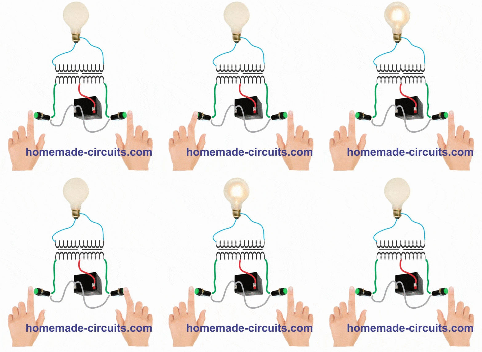
The following manual simulation shows the basic operating principle of a center tap transformer based push pull inverter circuit.
When the primary winding is switched alternately with a battery current, an equivalent amount of voltage and current is induced across the secondary winding through flyback mode, which illuminates the connected bulb.
In a circuit operated inverters the same operation is implemented but through power devices and an oscillator circuit which switches the winding at a much faster pace, usually at the rate of 50Hz or 60Hz.
Thus, in an inverter the same action due to fast switching would cause the load to appear always ON, although in reality the load would be switched ON/OFF at 50Hz or 60Hz rate.
How the Transformer Converts a given Input
As discussed above, the transformer usually will have two winding, one primary and the other secondary.
The two winding react in such a way that a when a switching current is applied at the primary winding would cause a proportionately relevant power to be transferred across the secondary winding through electromagnetic induction.
Therefore suppose, if the primary is rated at 12V and the secondary at 220V, an oscillating or pulsating 12V DC input to the primary side would induce and generate a 220V AC across the secondary terminals.
However, the input to the primary cannot be a direct current, meaning though the source may be a DC, it must be applied in a pulsed form or intermittently across the primary, or in the form of a frequency at the specified level, we have discussed this in the previous section.
This is required so that the inherent attributes of an inductor can be implemented, according to which an inductor restricts a fluctuating current and tries to balance it by throwing an equivalent current into the system during the absence of the input pulse, also known as flyback phenomenon.
Therefore when the DC is applied, the primary stores this current, and when the DC is disconnected from the winding, allows the winding to kick back the stored current across its terminals.
However since the terminals are disconnected, this back emf gets induced into the secondary winding, constituting the required AC across the secondary output terminals.
The above explanation thus shows that a pulser circuit or more simply put, an oscillator circuit becomes imperative while designing an inverter.
Fundamental Circuit Stages of an Inverter
To build a basic functional inverter with reasonably good performance, you will need the following basic elements:
- Transformer
- Power Devices, such as N-channel MOSFETs or NPN Biploar Power Transistors
- Lead Acid Battery
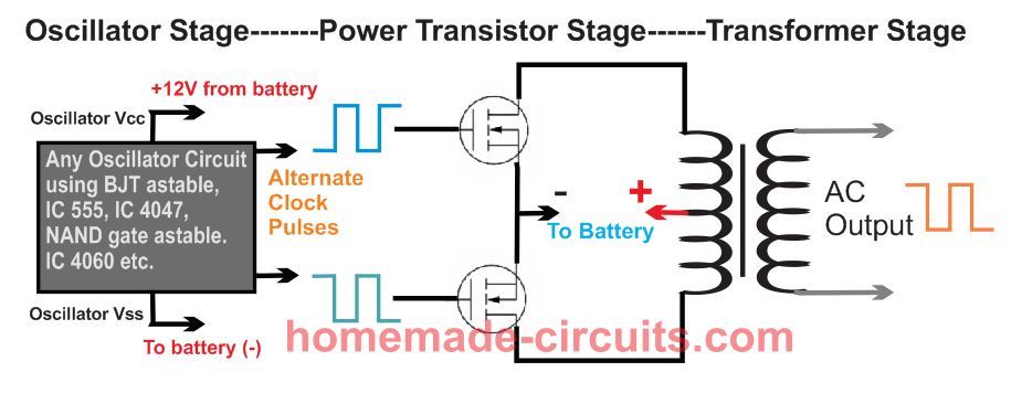
Block Diagram
Here's the block diagram which illustrates how to implement the above elements with a simple configuration (center tap push-pull).
How to Design an Oscillator Circuit for an Inverter
An oscillator circuit is the crucial circuit stage in any inverter, as this stage becomes responsible for switching the Dc into the primary winding of the transformer.
An oscillator stage is perhaps the simplest part in an inverter circuit. It's basically an astable multivibrator configuration which can be made through many different ways.
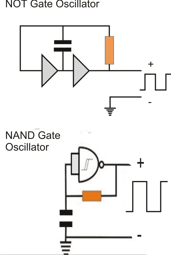
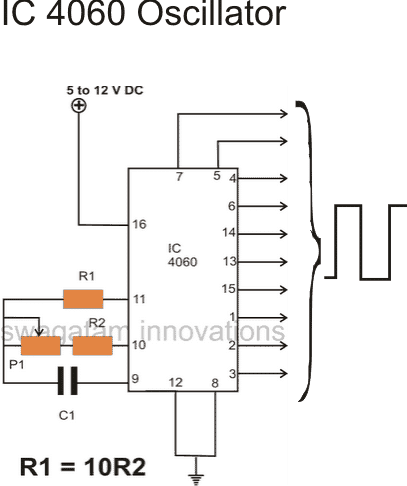
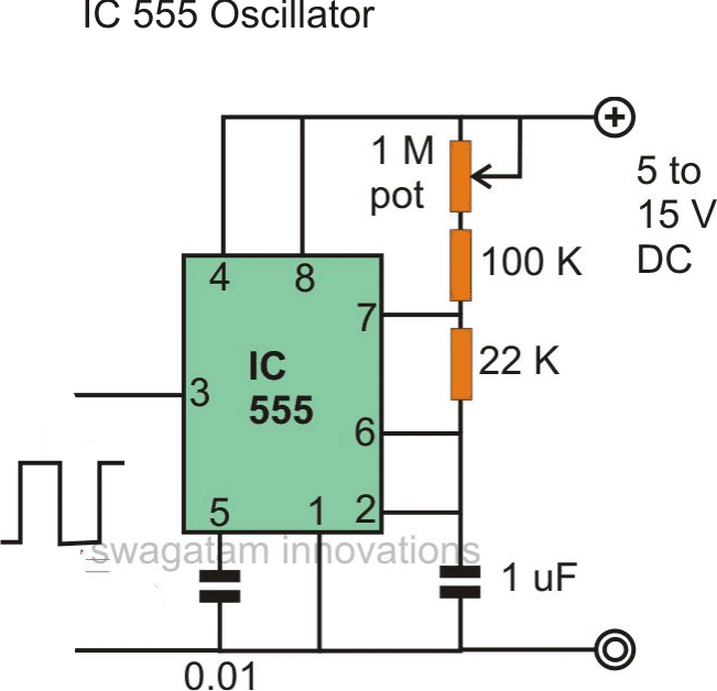
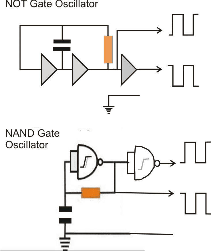
You can use NAND gates, NOR gates, devices with built-in oscillators such as IC 4060, IC LM567 or just utterly a 555 IC. Another option is the use of transistors and capacitors in standard astable mode.
The following images show the different oscillator configurations which can be effectively employed for achieving the basic oscillations for any proposed inverter design.
In the following diagrams we see a few popular oscillator circuit designs, the outputs are square wave which are actually positive pulses, the high square blocks indicate positive potentials, the height of the square blocks indicate the voltage level, which is normally equal to the applied supply voltage to the IC, and the width of the square blocks indicate the time span for which this voltage stays alive.
The Role of an Oscillator in an Inverter Circuit
As discussed in the previous section, an oscillator stage is required for generating basic voltage pulses for feeding the subsequent power stages.
However the pulses from these stages can be too low with their current outputs, and therefore it cannot be fed directly to the transformer or to the power transistors in the output stage.
In order to push the oscillation current to the required levels, an intermediate driver stage is normally employed, which might consist of a couple of high gain medium power transistors or even something more complex.
However today with the advent of sophisticated mosfets, a driver stage may be completely eliminated.
This is because mosfets are voltage dependent devices and does not rely on current magnitudes for operating.
With the presence of a potential above 5V across their gate and source, most mosfets would saturate and conduct fully across their drain and source, even if the current is as low as 1mA
This makes conditions hugely suitable, and easy for applying them for inverter applications.
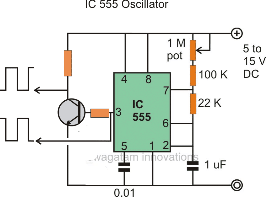
We can see that in the above oscillator circuits, the output is a single source, however in all inverter topologies we require an alternately or oppositely polarized pulsing outputs from two sources. This can be simply achieved by adding an inverter gate stage (for inverting the voltage) to the existing output from the oscillators, see the figures below.
Configuring Oscillator Stage to Design Small Inverter Circuits
Now let's try to understand the easy methods through which the the above explained with oscillator stages can be attached with a power stage for creating effective inverter designs quickly.
Designing an Inverter Circuit using NOT Gate Oscillator
The following figure shows how a small inverter can be configured using a NOT gate oscillator such as from the IC 4049.
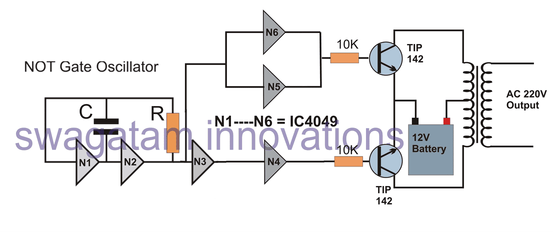
Here basically N1/N2 forms the oscillator stage which create the required 50Hz or 60Hz clocks or oscillations required for the inverter operation. N3 is used for inverting these clocks because we need to apply oppositely polarized clocks for the power transformer stage.
However we can also see N4, N5 N6 gates, which are configured across the input line and output line of N3.
Actually N4, N5, N6 are simply included for accommodating the 3 extra gates available inside the IC 4049, otherwise only the first N1, N2, N3 could be alone used for the operations, without any issues.
The 3 extra gates act like buffers and also make sure that these gates are not left unconnected, which can otherwise create adverse effect on the IC in the long run.
The oppositely polarized clocks across the outputs of N4, and N5/N6 are applied to the bases of power BJT stage using TIP142 power BJTs, which are capable of handling a good 10 amp current. The transformer can be seen configured across the collectors of the BJTs.
You will find that no intermediate amplifier or driver stages are used in the above design because the TIP142 itself has an internal BJT Darlington stage for the required in-built amplification and therefore are able to comfortably amplify the low current clocks from the NOT gates into high current oscillations across the connected transformer winding.
More IC 4049 inverter designs can found below:
Homemade 2000 VA Power Inverter Circuit
Simplest Uninterrupted Power Supply (UPS) Circuit
Designing an Inverter Circuit using Schmidt Trigger NAND gate Oscillator
The following figure shows how an oscillator circuit using IC 4093 can be integrated with a similar BJT power stage for creating a useful inverter design.
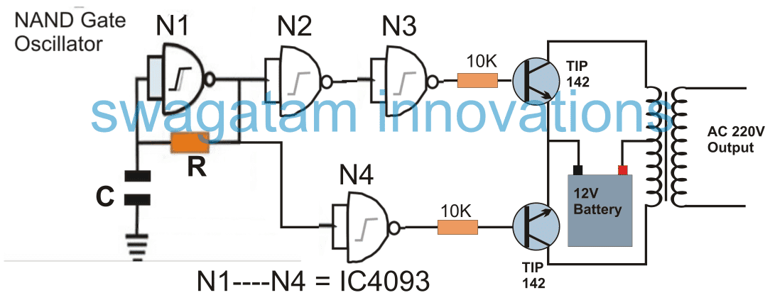
The figure demonstrates a small inverter design using IC 4093 Schmidt trigger NAND gates. Quite identically here too the N4 could have been avoided and the BJT bases could have been directly connected across the inputs and the outputs N3. But again, N4 is included to accommodate the one extra gate inside the IC 4093 and to ensure that its input pin not left unconnected.
More similar IC 4093 Inverter designs can be referred from the following links:
Best Modified Inverter Circuits
How to Make a Solar Inverter Circuit
How to Build a 400 Watt High Power Inverter Circuit with Built in Charger
How to Design an UPS Circuit – Tutorial
Pinout diagrams for the IC 4093 and IC 4049
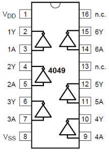
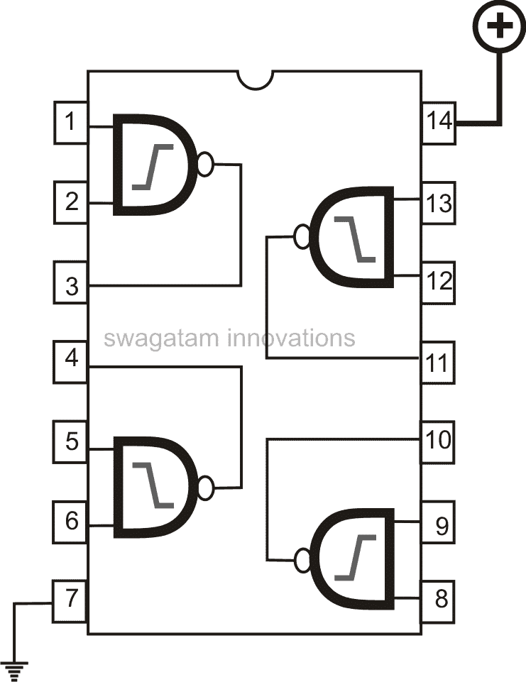
NOTE: The Vcc, and Vss supply pins of the IC are not shown in the inverter diagrams, these must be appropriately connected with the 12V battery supply, for 12V inverters. For higher voltage inverters this supply must be appropriately stepped down to 12V for the IC supply pins.
Designing a Mini Inverter Circuit using IC 555 Oscillator
From the above examples, it becomes quite evident that the most basic forms of inverters could be designed by simply coupling a BJT + transformer power stage with an oscillator stage.
Following the same principle an IC 555 oscillator can be also used for designing a small inverter as shown below:
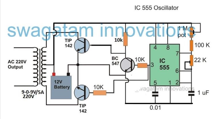
The above circuit is self explanatory, and perhaps does not require any further explanation.
More such IC 555 inverter circuit can be found below:
Simple IC 555 Inverter Circuit
Understanding Inverter Topologies (How to Configure the Output Stage)
In the above sections I have explained about the oscillator stages, and also the fact that the pulsed voltage from the oscillator goes straight to the preceding power output stage.
There are primarily three ways through which an output stage of an inverter may be designed.
By Using a:
- Push Pull Stage (with Center Tap Transformer) as explained in the above examples
- Push Pull Half-Bridge Stage
- Push Pull Full-Bridge or H-Bridge Stage
The push pull stage using a center tap transformer is the most popular design because it involves simpler implementations and produces guaranteed results.
However it requires bulkier transformers and output is lower in efficiency.
A couple of inverter designs can be seen below which employs a center tap transformer:
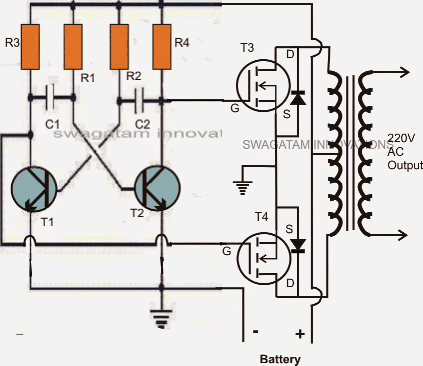
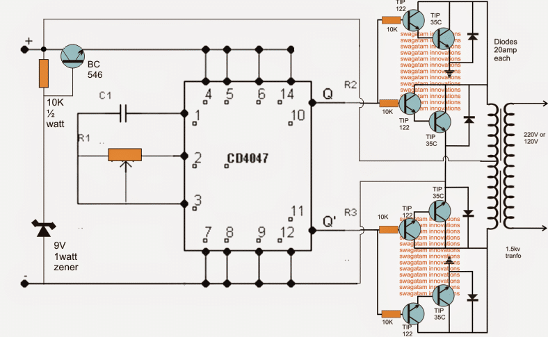
In this configuration, basically a center-tap transformer is used with its outer taps connected to the hot ends of the output devices (transistors or mosfets) while the center tap either goes to the negative of the battery or to the positive of the battery depending upon the type of devices used (N type or P type).
Half-Bridge Topology
A half bridge stage does not make use of a center tap transformer.
A half bridge configuration is better than a center tap push pull type of circuit in terms of compactness and efficiency, however it requires large value capacitors for implementing the above functions.
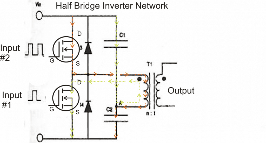
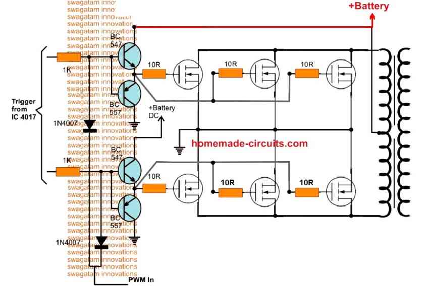
A full bridge or an H-bridge inverter is similar to a half bridge network since it also incorporates an ordinary two tap transformer and does not require a center tap transformer.
The only difference being the elimination of the capacitors and the inclusion of two more power devices.
Full-Bridge Topology
A full bridge inverter circuit consists of four transistors or mosfets arranged in a configuration resembling the letter "H".
All the four devices may be N channel type or with two N channel and two P channel depending upon the external driver oscillator stage that's being used.
Just like a half bridge, a full bridge also requires separate, isolated alternately oscillating outputs for triggering the devices.
The result is the same, the connected transformer primary is subjected to a reverse forward kind of switching of the battery current through it. This generates the required induced stepped up voltage across the output secondary winding of the transformer. Efficiency is highest with this design.
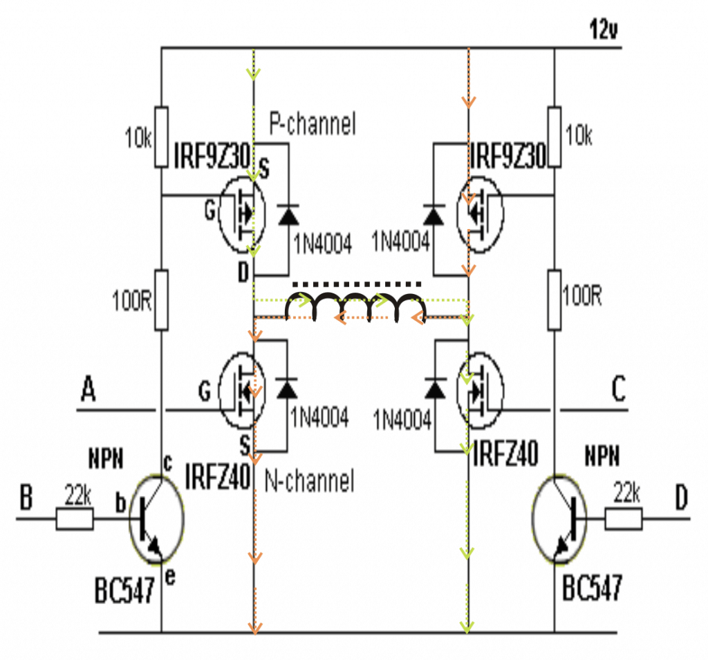
H-Bridge Transistor Logic Details
The following diagram shows a typical H-bridge configuration, the switching are made as under:
- A HIGH, D HIGH - forward push
- B HIGH, C HIGH - reverse pull
- A HIGH, B HIGH - dangerous (prohibited)
- C HIGH, D HIGH - dangerous (prohibited)
The above explanation provides the basic information regarding how to design an inverter, and may be incorporated only for designing a ordinary inverter circuits, typically the square wave types.
However there are many further concepts that may be associated with inverter designs like making a sine wave inverter, PWM based inverter, output controlled inverter, these are just additional stages which may be added in the above explained basic designs for implementing the said functions.
We will discuss them some other time or may be through your valuable comments.


Questions & Answers
No, the above circuits are not suitable for 48V, you can try the following design with 48V:
https://www.homemade-circuits.com/2012/09/mini-50-watt-mosfet-inverter-circuit.html
use BC546 for T1 and T2.
Good day,
Please make the basic design first and then we can gradually try upgrading it for more power.
You can try the following basic model first and then go on upgrading it with more mosfets for getting more power:
https://www.homemade-circuits.com/2012/09/mini-50-watt-mosfet-inverter-circuit.html
T1/T2 must be replaced with BC546 for 50V supply.
hello sir
do you have 3 ph inverter design, in 1 ph 220v 0ut 3 ph 220V 400Hz, with simple design
thks
reply
I am sorry cnc, presently I do not have this design.
what is the use of bc547 or any transistor in this circuit
for making frequency.
hi,i need 1000w circuit diagram of ups
Hi question = cncmesin but an investor to 220AC 220AC single phase of variable frequency from 50 to 400Hz you could make the sine wave generator integrated or L298 TB6560? and place suitable for 220V mosfet
thank you very much
Yes it's possible, thanks for the good suggestion!
Hello swagatam, will this circuit(link below) give me a modified sinewave?
4.bp.blogspot.com/-Uepf26wgJO0/TpQGZ-0QbHI/AAAAAAAABA4/lb51Ejk9SAs/s1600/12+to+220V+modified+sinewave+inverter.jpg
Hello ifeanyi,
yes it will work and give you a modified sine wave,.
sir i also want to know all information about inverter
Hello Swagatam,
i need to convert 12v dc to 120v ac with at least 5 amp load capacity.
i need a suggestion what could use for my purpose.
could u suggest me ???
thank you
Hello Rudra,
you can try the circuit design shown in the following link:
https://www.homemade-circuits.com/2012/09/mini-50-watt-mosfet-inverter-circuit.html
Hi dear Swagatam, I am ur fan & have built many projects for my personal use with success & had a lot of pleasure. God bless you. Now I intend to build a 1000 watt UPS with a different concept (inverter with high voltage input dc). I will use a battery bank of 18 to 20 sealed batteries in series each 12 volts/ 7 Ah to give a 220+ volts storage as input to a transformerless inverter. Can you suggest a simplest possible circuit for this concept which should include a battery charger + protection and auto switching by mains failure. Later I will include a solar power input too.
Thank You Aquarius!
I'll try to post it soon and let you know, most probably I would publish it within a couple of days.
Hi again, I hope you will soon be able to suggest a suitable circuit for my project requested in my last mail of March 17. …. Aquarius
Aquarius, please refer to this post:
https://www.homemade-circuits.com/2014/03/1000-watt-ups-circuit.html
My heartiest thanks for the circuit. i will build this one soon and let you know the result. Aquarius.
you are welcome!
Can u plz name some alternatives to the mosfets IRF9Z30 and IRFZ40 coz they arent available in my area
you can try IRF9540 and IRF540
would I need a gate driver if i am generating the PWM from a micro controller?
with 5v out, gate driver won't be required.
what if I have a 12V out
Thanks a lot buddy 😀
MCUs don't have 12V out, but 12v would be also suitable for driving msfets directly.
Can etch and use this circuit with a load of 200W.
Thanks a lot
Hi dear Swagatam, I intend to build a 1000 watt UPS with a different concept (inverter with high voltage input dc). I will use a battery bank of 18 to 20 sealed batteries in series each 12 volts/ 7 Ah to give a 220+ volts storage as input to a transformerless inverter. Can you suggest a simplest possible circuit for this concept which should include a battery charger + protection and auto switching by mains failure. Later I will include a solar power input too.
Hi Taiye,
I'll to post the design soon in my blog for your reference, please keep in touch.
I have seen you made similar inverters to this, I tried this one, it works duty cycle is 50% and voltage would be ok if I used the correct transformer but the frequency is 282hz do you know how I coud get it to 50hz?
which one are you referring to? please provide me with the link?
adjust the IC 555 frequency pot to acquire the desired frequency at the output of the inverter
The lowest settings of the pot is 282hz and wen I adjust the pot it will go all the way to little above 1khz, it doesnt go as low as 50hz
remove the 500k preset from the shown position and connect it in series with the 10k resistor, now you'll be able to achieve lower values..
Hii sir ,
What is value of resistance in 5th circuit
you can use 10k for both the resistors.
thanks it worked perfectly, I dont know how that worked but it did
you can modify it and repost it that would be nice, probably getting it to use a 12v transformer would be nice because this circuit works well.
thanks, I may do it in my free time…
Hi sir i wanted to make a simple inverter, i saw a video on YouTube "Make an inverter : DIY Experiments [#2] power AC devices with battery ".circuit diagram is at end of video, there he use 12-0-12v(dc) to 220/230v(ac)transformer.but I'm not getting how much amps transformer he used ??
Is it ok if i use 12-0-12v to 220v&2amps transformer?if not suggest me a better one sir
It will depend on how much load (watts) you intend to operate with the transformer output…just divide this requirement with 12V and you'll get the amp value….suppose you are planning to use 300 watt load with the trafo, then dividing this with 12V gives, 300/12 = 25 amps so you'll neeed a 12-0-12V/25amp/220V trafo for operating 300 watt load with a 14V/150AH battery
with 12V/2amps…the output power won't be more than 2 x 12 = 24 watts.
Hi sir i wanted to make a simple inverter, i saw a video on YouTube "Make an inverter : DIY Experiments [#2] power AC devices with battery ".circuit diagram is at end of video, there he use 12-0-12v(dc) to 220/230v(ac)transformer.but I'm not getting how much amps transformer he used ??
Is it ok if i use 12-0-12v to 220v&2amps transformer?if not suggest me a better one sir
Hi Swagatam can you help me with something why is it that even though I have a dc circuit if I put it to measure ac it shows a voltage measurement
A DC content will always have some superimposed AC content which is also called ripple, therefore if measured in the AC range this will become apparent.
let's give me the knowledge I I want to be 400 VDC 220VAC you are using diagram baruti.themigambo@gmail.com
i have an ups.. damaged board. tried to repair. but all in vain. its a 300w ups. its trafo is working good. during repair i bought 4 of its irfz44n.. so the thing is.. could you please guide me building a circuit for that.. it got a H kinda circuit n trafo isnt centre-tapped.. i tried making a circuit using tip127 n tip122 also with bc547 n mje3055… everything failed. i also have a 4047ic… its my humble request to please design a circuit using bc547, cd4047.. so that it may atleast provide 250w ac.. 300w trafo means has a capacity of atleast 20amps/12vdc. i am already having 3 of 12v 7.5AH batt…!!
please help as soon as possible..
thanx for all the circuits..
a 4047 IC inverter will require a center tap transformer, for a two wire transformer you will require an H-bridge driver circuit as explained in the following article:
https://www.homemade-circuits.com/2014/01/simplest-full-bridge-inverter-circuit.html
the "load" needs to be replaced with the transformer primary winding