In this post I will elaborately explain how to build a simple LM317 based adjustable power supply circuit using minimum number of external components.
As the name suggests a variable power supply circuit provides the user with a range of linearly varying output voltages through a manually controlled potentiometer rotation.
A LM317 is a versatile device which helps an electronic hobbyist to build a variable voltage power supply quickly, cheaply and very efficiently.
Introduction
Whether it’s an electronic noob or an expert professional, an adjustable power supply unit is required by everybody in the field.
It is the basic source of power that may be required for various electronic procedures, right from powering intricate electronic circuits to the robust electromechanical devices like motors, relays etc.
A variable power supply unit is a must for every electrical and electronic work bench and it’s available in a variety of shapes and sizes in the market and also in the form of schematics to us.
These may be built using discrete components like transistors, resistors etc. or incorporating a single chip for the active functions.
No matter what the type may be, a power supply unit should incorporate the following features to become a universal and reliable with its nature:
Essential Features
- It should be fully and continuously adjustable with its voltage and current outputs.
- Variable current feature can be taken as an optional feature because it’s not an absolute requirement with a power supply, unless the usage is in the range of critical evaluations.
- The voltage produced should be perfectly regulated.
With the advent of chips or ICs like LM317, L200, LM338, LM723, configuring power supply circuits with variable voltage output with the above exceptional qualities has become very easy nowadays.
How to Use LM317 for Producing a Variable Output
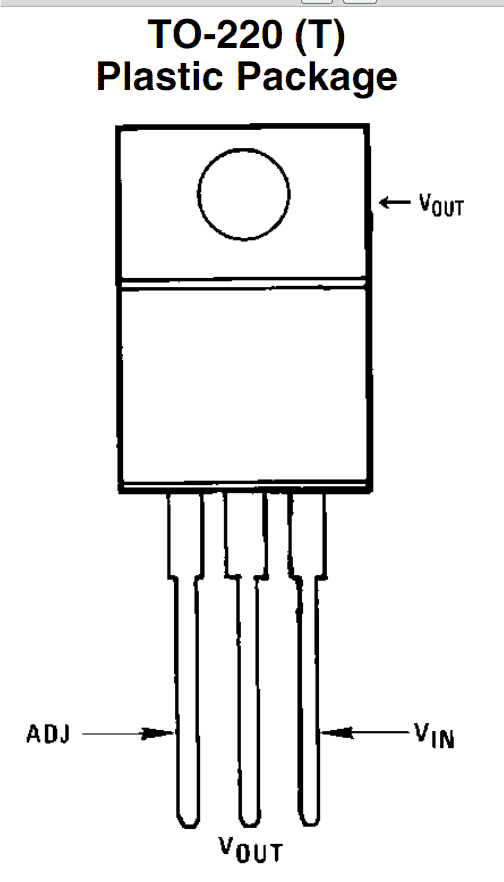
Here I have explained how to construct a simplest power supply circuit using the IC LM317. This IC is normally available in TO-220 package and has three pin outs.
The pin outs are very easy to understand, since it consists of an input, an output and an adjustment pins that just needs to be wired up with the relevant connections.
The input pin is applied with a rectified DC input, preferably with the maximum tolerable input, that’s 24 volts as per the specs of the IC.
The output is received from the “out” pin of the IC while the voltage setting components are connected around the adjustment pin.
How to Connect LM317 in a Adjustable Voltage Power Supply Design
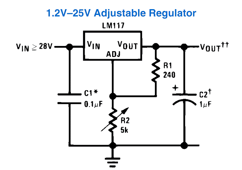
As can be seen the diagram, the assembly needs hardly any components and is in fact a child’s play to get everything in place.
Adjusting the pot produces a linearly varying voltage at the output that may be right from 1.25 volts to the maximum level supplied at the input of the Ic.
Though the shown design is the simplest one and therefore includes only a voltage control feature, a current control feature can also be included with the IC.
Output Voltage Formula
The output voltage (Vout) of the LM317 can be calculated through the two external resistors, R1 and R2, using the formula:
Vout = 1.25 * (1 + R2 / R1)
Where:
- 1.25V is the reference voltage between the Adjust and Output pins.
- R1 is the resistor between the Output pin and the Adjust pin (typically 240Ω).
- R2 is the resistor between the Adjust pin and ground.
Current Through Resistor R1
The current I1 through resistor R1 is approximately:
I1 = 1.25 / R1
If R1 = 240Ω, the current is:
I1 ≈ 5.21 mA
Adjusting the Output Voltage
To set a desired output voltage we can choose the resistors R1 and R2 accordingly. For example if R1 = 240Ω and you want Vout = 5V then you can rearrange the formula for Vout to solve for R2:
5V = 1.25V * (1 + R2 / 240Ω)
Solving for R2 gives:
R2 = 720Ω
Maximum Output Voltage
The output voltage is limited by the input voltage and the LM317's dropout voltage, which is typically around 3V. The maximum output voltage (V_out) is:
Vout = Vin - Vdropout
For example if Vin = 12V and the dropout voltage is 3V then maximum output voltage would be:
Vout = 12V - 3V = 9V
Power Dissipation in the LM317
The LM317 dissipates power as heat, and this power dissipation (Pdiss) is calculated as:
Pdiss = (Vin - Vout) * Iout
Where:
- Vin is the input voltage.
- Vout is the output voltage.
- Iout is the output current.
For example if Vin = 12V, Vout = 5V, and Iout = 1A, then power dissipated by the LM317 would be:
Pdiss = (12V - 5V) * 1A = 7W
Adding a Current Control Feature
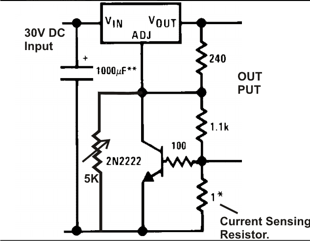
The figure above shows, how the IC LM317 can be effectively used for producing variable voltages and currents, as desired by the user.
The 5K pot is used for adjusting the voltage, whereas the 1 Ohm current sensing resistor is selected appropriately to acquire the desired current limit.
Enhancing with High Current Output Facility
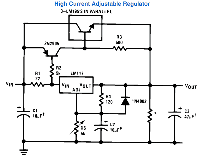
The IC can be further enhanced for producing currents higher than its rated values. The diagram below shows how the IC 317 can be used for producing more than 3 amps of current.
LM317 Variable Voltage, Current Regulator
Our versatile IC LM317/338/396 may be used as an adjustable voltage and current regulator through simple configurations.
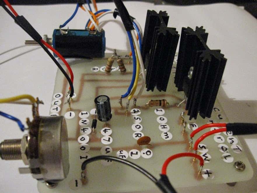
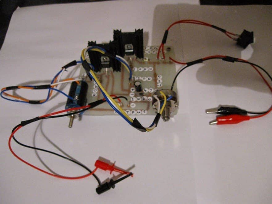
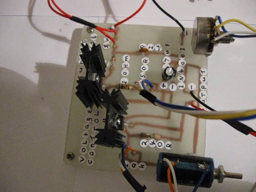
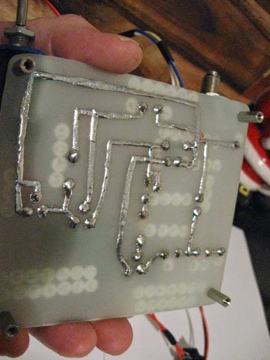
The idea was built and tested by one of the avid readers of this blog Mr. Steven Chiverton and used for driving special laser diodes which are known to have stringent operating specifications, and could be driven only through specialized driver circuits.
The discussed LM317 configuration is so accurate that it becomes ideally suitable for all such specialist current and voltage regulated applications.
Circuit Operation
Referring to the shown circuit diagram, the configuration looks pretty straightforward, two LM317 IC s can be seen, one configured in its standard voltage regulator mode and the other in a current control mode.
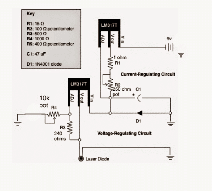
To be precise the upper LM317 forms the current regulator stage while the lower acts like a voltage controller stage.
The input supply source is connected across the Vin and ground of the upper current regulator circuit, the output from this stage goes to the input of the lower LM317 variable voltage regulator stage.
Basically both the stages are connected in series for implementing a complete foolproof voltage and current regulation for the connected load which is a laser diode in the present case.
R2 is selected to acquire a range of around 1.25A max current limit, the minimum allowable being 5mA when the full 250 ohms is set in the path, meaning the current to the laser may be set as desired, anywhere between 5mA to 1 amp.
Calculating the Output Voltage
The output voltage of a LM317 power supply circuit could be determined with the following formula:
VO = VREF (1 + R2 / R1) + (IADJ × R2)
where is = VREF = 1.25
Current ADJ is usually around 50 µA and therefore too negligible in most applications. You can ignore this.
Calculating Current Limit
The above is calculated by using the following formula:
R = 1.25/max allowable current
The current controlled voltage acquired from the upper stage is next applied to the lower LM317 voltage regulator circuit, which enables the desired voltage to be set anywhere from 1.25V to 30V, here the max range being 9V since the source is a 9V battery. This is achieved by adjusting R4.
The discussed circuit is assigned to handle not more than 1.5amps, if higher current is required, both the ICs may be replaced with LM338 for obtaining a max 5amp current or LM396 for a max of 10amp current.
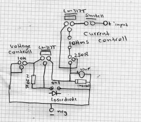
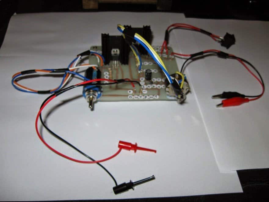
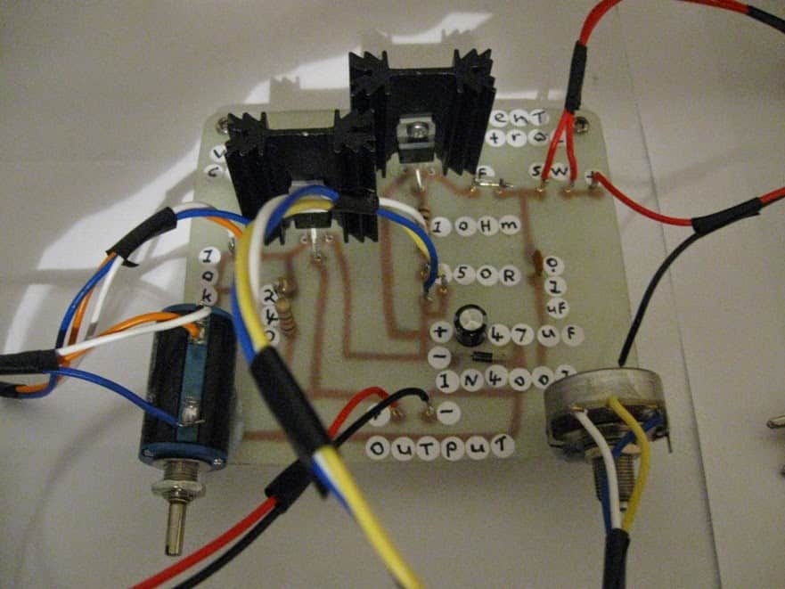
The following lovely pictures were sent by Mr. Steven Chiverton, after the circuit was built and verified successfully by him.
Prototype Images
Upgrading LM317 with Push Button Voltage Control
So far we have learned how to configure an LM317 for producing adjustable output using a pot, now I have explained how push buttons may be used for enabling digitally controlled voltage selection.
We eliminate the use of mechanical pot and replace it with a couple of push buttons for the up/down selection of the desired voltage levels.
The innovation converts the traditional LM317 power supply design into a digital power supply design, by eliminating the low tech potentiometer which might be prone to wear and tear in the long run resulting in erratic operations and incorrect voltage outputs.
The modified LM317 design which would be allow it to respond to the push button selections can be seen in the following diagram:
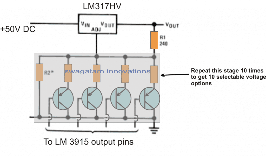
The R2 resistors associated need to be calculated with respect to R1 (240 ohms) for setting up the intended push button selected voltage outputs.
High Current LM317 Bench Power Supply
This high current LM317 power supply can be used universally for any application that requires a high quality regulated high current DC supply, such as car sub woofer amplifiers, battery charges etc.
This power supply is designed to be as versatile as feasible, while also ensuring that the parts count stays low and affordable.
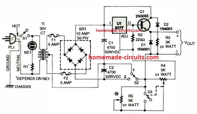
This simple LM317 fixed os adjustable voltage supply satisfies the conditions superbly and is capable of delivering up to 10 amps.
The voltage output is governed by the circuit stage containing R4, R5 and S3; observe that switch S3 is a part of R4.
For getting a fixed voltage output, R4 must be determined for getting zero ohms (fully counter-clockwise). In this situation, switch S3 should be in the open position.
The preset R5 should in that case be tweaked so that the circuit generates a 12 volt output (or anything your personal application requires).
To have an variable output, R4 can be flipped clockwise, with S3 in the closed position, and getting rid of R5 from the circuit.
The output voltage can now be operated by the R4 resistor solely. When the position of SPDT switch S2 is in 1, the highest output current can be accomplished having the two halves of T1 supplying current to the filter stage, in order to increase the overall current output 2 times more.
Having said that, the highest output voltage will be reduced by 50% in this position. It really is a much productive setting considering that the power transistor does not have to drop a significant amount of potential.
In position 2, the maximum voltage practically equals the power specifications of T1. Here, we employed a 24 volt center-tapped transformer for T1.
Lastly, D1 and D2 had been incorporated to safeguard the LM317 IC in case power was switched off with an inductive load at the output


Questions & Answers
hello sir, I want to ask that for the above circuit which dynamo would be suitable as we want to charge our laptop from dynamo by using it in our bike wheel. and to charge a laptop e will require atleast 24v and from dynamo I don't know this much power can be generated or not and if it can be done then which dynamo will be used as there are different types of dynamo.
so should we use a d.c. motor as an input source or dynamo can work here. and please specify the ratings and type of d.c. motor or dynamo.
Thank you.
Hello concor,
you can use any small dynamo rated at around 28V/2amp for the project, the dealer will be able to advise you better with the product.
Dear sir
Aap ne jo 7805 ke help se charger banane ki idea diya hai thanx for that . maine kal wo banake dekha . to successfully run hua . but wo 12v 12amp pe chalane ke bad hot ho raha tha . to plz usake liye koi solution batawo . sir muze actually muti pin charger aur sibhi automobile battery ke liye (motorcycle , car , truck )ke liye charger banana tha . so plz help me sir
Dear Shrikant,
Use a large aluminum heatsink with the 7805 IC for preventing it from getting hot.
For using the circuit with many cell phiones you can try the folowing design
4.bp.blogspot.com/-6nMOBLLNkTQ/UgMfLIQHHRI/AAAAAAAAE8w/Ke2Ci0w91Oo/s1600/LM123%20Cell%20phone%20charger%20circuit.png
50mA per second is huge, it's the problem of your clock not the battery configuration, I don't think any external circuit can help to reduce this.
If you increase the voltage from 1.5 to 1.8 would force the clock to consume even more current so that's not a correct approach, and the opamp has no role in the situation.
One method could be to use LM317 with an input of 2.4V and output of 1.25V supplying the clock
Another possible way could be to use a joule thief circuit.
Hello Mr. Majumdar. What have to be done differently to adjust the output current to a specific value? I mean I would like to make the available current adjustable to that it could go through a digital ammeter before the terminal. Also, for the high current circuit, how should the circuit be fused? Thank you.
Hi Courtney,
Please refer to the following posts where you will find a simple method of controlling current using a variable resistor:
https://www.homemade-circuits.com/2013/06/universal-high-watt-led-current-limiter.html
Hi Swagatam
I need your help to get rid of the frustration I am experiencing with my first LM317 circuit.
As the configuration is quite simple, I soldered the components on PCB straightaway. The value of the resistor was selected based on the value of the POT and the required output voltage (30V). The step down transformer is about 500mA
Initially the 30V-analog voltmeter would show more than 30V. When I adjusted the POT, I noticed some spark or flash inside the POT. And then the output remains within 28V-32V. The current consumption of the load is hardly 100mA.
I assembled fresh components on a breadboard but same results. I checked the circuit on the simulator, it works perfectly…………….so where am I wrong???
Hi Abu-Hafss,
R1 could be 240 ohms or a 120 ohms, it won't make any difference as long the pot is selected for satisfying both the values… in other words a 10K pot would be just enough.
so R1 is not so crucial.
There's hardly anything one can suggest regarding the troubleshooting of the first circuit, because it's as simple as can be.
Only two things which you probably know that could be causing the problems are, incorrect pin connections, or faulty (duplicate) devices. there's nothing else that could blow these devices of as these devices have a thorough and very robust internal protection circuitry.
Hi Swagatam
Here is how I made the connections.
So far I have used 3 devices unsuccessfully. None of them blew, instead I noticed flash inside the POT. Please confirm if R1 is 1/4W rated.
I have updated the connection diagram. Please re-check. That is how I am connecting the components.
I have tried another IC (4th one). When the POT is providing very low resistance the voltmeter shows about 5V. When trying to rotate the shaft of the POT, I can see light inside the POT which means it cannot withstand the current flowing thru it. Do I have to use a wire-wound POT?
Hi Abu-Hafss,
use a new IC and try with a 24V supply, I think the 36V input could be damaging the IC….and it should 240 ohms for R1 and 10k for R2 ideally.
Just fried the 220 ohms resistor when used with 10k wire-wound POT.
Supply is 32V. And there is no load, no C2 only a 30V analog voltmeter.
I assume, earlier the carbon film of 5K POT could not withstand the I(adj) and now the 220 ohms resistor failed to withstand that current. Why I(adj) is so high?
As per datasheet the output voltage range is 1.5 – 37V. And input voltage must be 1.5V higher than the output, which means to get 37V at output the input should be 38.5V ! However, in my case the input is not 36V, it is 32V.
Ok, I will try with 220R (240R not have) and 10k POT.
I checked with 24V supply:
R1=180, R2=5K POT, Output 24V at low R2 and high R2, POT frying.
R1=180, R2=10K POT wire wound, Output 1.5V at low R2, 24V at slight increase in R2, R1 heating up.
I have tried the fifth and last LM317…………all behaving similarly.
Hi Abu-Hafss,
You decide how this can be possible, LM317 can be never wrong, its datasheet cannot be wrong, the indicated part values cannot be wrong.
I am suspecting that the entire lot of your LM317 could be duplicate and faulty… assuming your connections to be perfectly correct as per the diagram.
a wire wound pot is not required, even a preset should work here.
That is what I also thinking. But, is there any way to check and confirm if all those 5 regulators are dude?
Hi Abu-Hafss,
the sparking of the pot itself suggests that the ADJ pin is shorted with the input pin which is probably causing the input supply to short to ground through the pot making all those sparks inside the pot.
Past 1 month observing yours technical article looks very helps
Thanks 😉
Hi sir,
I came across your work on “Bicycle Dynamo Battery Charger Circuit” in Homemade circuit design blog. It was really informative. I would like to ask something regarding that article. I am working on a hexapedal robot with battery switching mechanism. Once the primary battery gets beyond a preset voltage, secondary battery will power up the robot’s system. My concern is not regarding the switching circuit. Together with this, I am working on energy generation by attaching a generator to each motor. The current generated is intended to be used to recharge 30C 11.1V 2200mAh 3 cell LiPo battery. I am aware that the circuit mentioned in “Bicycle Dynamo Battery Charger Circuit” will not be useful for my purpose. Can you give me any other option pertaining my issue. I just need to know on how to modify the circuit to make it LiPo compatible. Thanks, looking forward for a reply.
Regards,
Arun Prashan
Hi Arun, yes I'll post the required design in this blog soon, may be by tomorrow, so please be in touch
By the way if you are assuming that you would be able to charge the battery with the same energy which is being used for operating the robot, that may be not feasible….the output will be always less than the input
Hi, I am trying to build a variable PSU using a 24 v smps and LM338. The circuit works but the output current is very low. The same circuit works with LM317. Could you advise me if any changes are needed in components for LM338. I have used the first circuit as shown here on top.
Hi, please provide all the info regarding what exactly you are trying to include in your power supply, and what are the input/output amp specs
I am trying to build a benchtop variable supply. I just require variable output using LM338, 5k wirewound potentiometer which will be used to vary the voltage.Input amperes is 3A and same is needed at output. The 24v SMPS is a ready made manufactured by meanwell. Hope this info is helpful.
The IC LM338 is designed to provide in excess of 5amps at its output, so if the input is 3amps you should get 3 amps full at the output of the IC, across the whole variable voltage range, if this is not happening your IC could be faulty(duplicate) or not connected correctly.
A 10k pot would work better than 5k
Thanks Swagatam, will try that.
Hi i tried the same circuit using 10k pot, still i get the same result. Now for the resistor between ADJ and Vout, do we need it to be of higher wattage, currently i am using 220 ohms 1/4 watt.
All resistors can be 1/4 watt rated, it cannot be an issue.
Hi Swagatam, As you said, the LM338 turned out to be faulty. I ordered same ICs from Texas Instruments samples and they worked perfectly.
Now another issues is do LM338 have short circuit protection ? If not can i use your suggested circuit which uses relay to protect the SMPS from damage ?
Hi Janesh, yes the LM338 has in-built output short circuit, over load protection, still for getting a desired current control you can add a BC547 transistor with the adj pin of the IC as shown in the following diagram…R4 is not important can be replaced with a wire link
https://www.homemade-circuits.com/2012/04/how-to-make-solar-battery-charger.html
Dear Mr Swagatam,
is there a possibility that a 5Amps 50Hz transformer be combined with timer to regulate the Vout? I've successfully built a variable bench power supply with ic L200 and a few power transistors, but I don't think it's efficient enough.
Dear imanul, i have no idea how a timer can be used for voltage/current regulation, one of the best options is shown in the above article first diagram, an LM338 may be used instead of Lm317 for a 5amp input
I'm sorry, not a timer, i mean some controller that's designed for smps, like pwm.
When using a linear regulator like LM317 I can feel a lot of heat on the heatsinks both from the ic and power transistors, and I believe that's a wasted power.
I googled the formula of the wasted heat, (Vin – Vout) x Amps.
eg. (18V – 6V) x 3A = 36Watts of wasted heat.
So if you could please teach me how I can get high efficiency by using alternative other than linear regulator. Building a complete smps, with ferrite core, is too hard for me.
the formula and the calculations that you have shown is true for resistors and zeners, not for these sophisticated power regulator ICs. These ICs may dissipate say about 10% of the total power, which is quite reasonable.
You can try LM338 circuit for your application, or if you are interested to get 99% efficiency then ferrite cored smps is the only way to go..
Thank you Mr. Swagatam, a new lesson learned today.
Anyway I'd like to stock up common diodes at home, like 1n4001. Most people recommend the 1n4007-the highest voltage rating ones. With their particularly equal price, why do the manufactuter still make the lower ones? When I go to the retailer and ask for 1n4001 they give me 1n4007 instead, and saying "its the same". I dont think it's true, a "marking" means "something", right. And what about 1n5819 Schottky diodes, should I stock them up for my everyday electronics? Can they be used as the substitute for the 1n400x series?
Thank you in advance Mr. Swagatam for your advice.
Thanks Imanul, yes the numbers definitely indicate a lot of things, 1N4007 is much better than 1N4001 in terms of reverse voltage handling capability, and nowadays all other variants are slowly getting obsolete except 1N4007.
1N5819 may be considered an enhanced version of 1N4007 in terms of speed and forward voltage drop but as far as voltage rating is concerned its far inferior just around 30V
Well…. Sir….we hav a project to design a 40mA power supply with transformer…. So basically I could be using either of these IC's…. But since we have just entered our branch I do not have knowledge to the depth…. Could you please suggest me what changes is to be done in the values of the passive components so as to get a 40mA power supply
you can try the first circuit with IC LM317….no changes in the component values is required, use a 50mA transformer in order to restrict the output current to the specified limit
Well…. Sir….we hav a project to design a 40mA power supply with transformer…. So basically I could be using either of these IC's…. But since we have just entered our branch I do not have knowledge to the depth…. Could you please suggest me what changes is to be done in the values of the passive components so as to get a 40mA power supply
Sir,
I have done this …
It working well..
But one problem… the IC LM317 is too heating when some load (like a 6 volt dc motor) is connecte. I also used a medium size heat sink.
So please tell me how can reduce the heating problem…
Thank you…
Narottam, Linear ICs like 317 and 338 will always heat up even with normal loads…it cannot be avoided, you can try LM338 instead and see the response
or try reducing the input voltage
Ooh…thanks Sir…
Also I thinking that if I use two IC(LMLM317 or LM338) in parallel than have any chance to reduce the heat ??
A single LM338 would be enough since it's rated to handle up to 5 amp current
Ok..
Thank you…very much… Sir..
I've seen some ckt on Google…they have a diode that is connected betwwen the Vin and Vout of the regulator..whats that for? can you explain? tnx
that's for protecting the IC in a situation where the output of the might have a filter capacitor, and the input of the IC is shorted to ground, which is never possible under normal conditions.
Can I change the current sensing resistor from fixed to a variable? like pot?
yes if you are able to get a value with the specific low Ohms range
So it needs a very low resistance? The higher the value..the lower the current? and vice versa?…
and where is the negative of the output? base or emitter?
yes that's correct, negative is at emitter, and positive at the base