In this article I have explained an alternator power booster circuit which was unveiled by one of the keen followers of this blog, Mr Michael Mbamobi. I have explained more about the details.
Technical Specifications
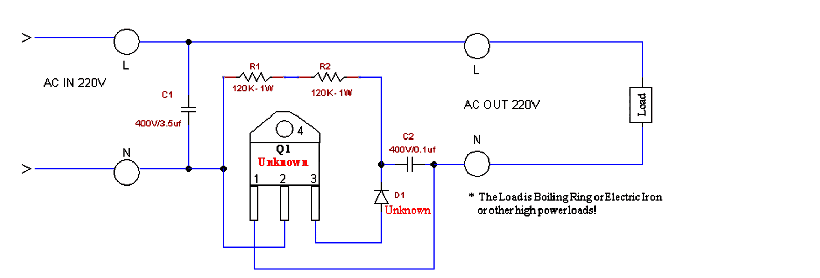
There is this circuit I want to show you. I want to show you the circuit through Homemade Circuit or Brighthub.
I didn't see how I can upload picture there. Please direct me I can sent this through Homemade Circuit. Anyway I uploaded the picture here! see the circuit and find out what these our Nigerian Guys are up to. I only hear about this type of device here in Nigeria.
I bought it and disassembled it. With your ability as Engr. Swagatam Majumdar, you can build a better device that can perform this same thing without depending on their own construction.
The folks call this an alternator power booster! It enables small gensets support loads bigger than their coils and feel alright with it without yearning!
I disassembled it carefully because D1, R1, R2, C2 and Q1 are obscured inside a glue like paste.
AC IN is from a small 650VA Generating set which is normally incapable of powering the connected loads.
The diode polarity and the value is not certain but this is its place in the circuit. It got broken while dismantling the glued circuit.
Q1 couldn't be traced either because the print was scraped of by the manufacture.Only its pin#1 and pin#3 responded to the DMM, it read zero like a dead diode, pin#2 does not read with any other pin at all. Pin#4 which is the tab is also unconnected.....just cannot figure out the device or its specs.
The diode D1 is blue in color, small glass type.
Solving the Circuit Request
Dear Michael,
It looks like an AC voltage booster circuit to me. Q1 is probably a power triac, the diode might be a diac DB-3, I am assuming this since it's small glass type and blue in color.
I would be addressing this circuit in my blog very soon....kindly stay tuned for the updates in my blog.
Thanks and Regards.
Circuit Explanation
This circuit is a simple AC voltage booster designed for supplying boosted voltage to high-power resistive loads like electric irons or boiling rings. Here's how it works:
Working Principle:
Capacitive Voltage Divider (C1)
The capacitor C1 (3.5µF, 400V) works like a reactive voltage dropper to provide a phase-shifted voltage for triggering the TRIAC (Q1).
It limits the current flowing into the gate of the TRIAC.
Gate Drive for the TRIAC (Q1)
Resistors R1 and R2 (120K, 1W each) form a voltage divider network which ensures a controlled gate drive for Q1.
The combination of D1 (Unknown, but likely a Diac) and C2 (0.1µF, 400V) creates a triggering delay, which allows phase control of the AC waveform.
Switching Action of TRIAC (Q1)
The TRIAC remains off until the breakover (firing) voltage of D1 (could be a Diac like for example a DB3) is reached.
When this happens then the D1 conducts, which sends a sharp pulse to the gate of Q1, turning it on.
The TRIAC then conducts ON, allowing the AC power to reach the load.
Voltage Boosting Mechanism
The phase angle of TRIAC conduction is controlled, which modifies the effective RMS voltage applied to the load.
By partially delaying the triac conduction, the circuit makes it possible to increase the peak voltage for the load.
The increase of the voltage across the load is achieved by extending the conduction duration of the AC cycle.
Main Features:
It Increases output voltage above input voltage (may not bee a true step-up transformer action but rather a phase-controlled voltage boost type).
It will Work effectively with resistive loads (boiling rings, irons, etc.).
This concept Uses phase angle control to regulate output power.
Capacitor C1 is a crucial component which helps to boost the voltage by acting as a reactive impedance.
Limitations:
This design is Not suitable for powering inductive loads (motors, transformers).
Here, the Voltage boost depends on the load resistance and the phase angle.
It Can create harmonics and waveform distortion in the AC supply line of the grid.
Mains Voltage Booster using Two Capacitors and Two Diodes
The above concept can also be implemented with the following circuit which is simpler than the above and is also a lot cheaper.
The capacitor ratings may be modified and experimented with as per the load, and individual preferences.
However this circuit can be used only for heater applications such as irons, heaters, geysers, ovens, toasters, blowers, dryers, hot air gun etc.
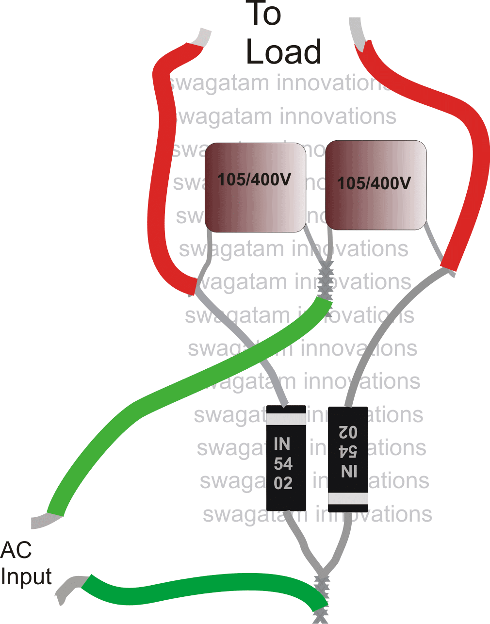
Please use 1N5408 diodes instead of 1N5402, mistakenly shown in the above diagram.



Questions & Answers
everything's already furnished in the above article.
It would be difficult to troubleshoot without seeing, actually my prototype worked very well, in fact the connected soldering iron became red hot within a minutes time and I had to switch power off to prevent the iron from blowing off.
1N5401 is not a problem, and if you are using a soldering iron at the output even a 1N4007 will work as diodes.
check the capacitors, they might be faulty.
I think the triac use in mr micheal cct is BT151 but the diode I can't tell. Pls try complete the cct ƒσя ♏ε̲̣̣̣̥
It's not recommended, but you can give it a try, if there's no audible noise from the fan then it could be fine.
please mr swagatam how can i make the above circuiy yo power a refrigerator
the above circuits will work only for heater types of resistive loads, not for other appliances.
it should be 105/400V not 104/400V. 104 = 0.1uF, 105 = 1uF so pls correct this in your circuit.
It will take time…just keep investigating the circuits and the concepts theoretically and practically, when in trouble put up your question here to get them answered appropriately…in this way you will be able to gradually grasp the many aspects and get stronger in the field.
Mr. Swagatan, please what exactly is the booster used for or what is the purpose of the booster?
Mr Eno, in the above shown circuits it's for boosting the performance of resistive appliances during low voltage conditions.
please what will happen when there is high or normal voltage conditions, won't it blow up the appliances?
yes it will damage the load (resistive only) if the input voltage is restored back to normal.
thanks for your explanations on this booster. actually I have built the first circuit by mr Michael and I connected the positive to Q1 instead of negative and the device worked without any humming noise but when I reversed my connection to as it is in the drawing above I.e with negative to Q1 I discovered that the device was humming, and also I connected a metre to the output socket the output with out load was 50v but with load 100v. please can you explain these my discoveries.
more so, instead of a ceramic capacitor can't I use polarised ones because I have 4700uf 25v &1000uf 25v and I have IN5392MIC.
lastly can I use a diode instead of diac? thank you.
to me the first circuit doesn't make any sense at all. C1 is connected directly across the power rail meaning it will only waste power and do nothing.
even if the circuit works it won't do anything significant.
the second circuit suggested by me has been tested by me and it really works, but only for resistive loads such as heaters
4700uF/25V will give you a big explosion.
pls sir i bought one of those power optimizer as it were called and dismantled it and the circuit looks exactly like the first one uploaded and it was working fine but when i dismantled it, i discovered that the component numbers were wiped off, so my question is this, cant the first one work owing to the fact that it really worked when bought and secondly what is ur take sir. pls reply me and once again thanks for educating me alot
Ekeh, if it was working before means it is a good design, but may be you broke something while trying to dismantle it, there must be something that was hidden and secret which you might have broke and that's why it isn't working now….
I am finding it difficult to simulate the first design so I can't suggest my opinion about it.
am confused sir u said and i quote "The capacitor ratings may be modified and experimented with as per the load, and individual preferences". what exactly do u mean by this? is it that the 105/400v can be increased or reduced? if that is true what will be the effect of such increase or reduction? also if i have a 600va gen set and i want to use a 1500watt iron on it, will ur modified circuit work? if no what do u advice?
yes you got it right, by increasing the uF of the capacitors in the second design you can increase the current or the wattage handling capacity of the circuit
but you cannot increase the output wattage than the input wattage by using any method, anywhere in this universe, that's not feasible.
I BUILT THE SECOND CIRCUIT YOU GAVE SIR BUT IT DIDNT WORK. WHEN I PLUG IT TO LIGHT THE SOCKET COMES ON BUT WHEN I PLUG AN ELECTRIC IRON TO THE SOCKET, THE LIGHT GOES OFF BUT MY GEN REMAINS ON. PLS WOT EXACTLY COULD BE THE PROBLEM. I NEED UR HELP PLS
I am not sure what you are trying do?
If you are thinking that this circuit will boost wattage then you may be wrong…the circuit will not boost wattage.
if your iron wattage is too big for the generator then no circuit in this world would be able to make it function.
the second circuit above will not boost voltage provided the wattage of the load is much smaller than the wattge of the fed input
….sorry I meant
the second circuit above will only boost voltage provided the wattage of the load is much smaller than the wattage of the fed input
as i posted earlier, i bought one of those power optimizer and i use a 650va generator set (called i pass my neighbour). this gen can not power up a 1500watt electric iron or heater but with the use of the optimizer/ power booster i was able to iron effectively and heat up my water several times and the first diagram looks exactly like d one i have. how i wish there is a way i an send u a snap shot of the components so u take a look at it yourself
if you are able to generate 1500VA from a 650VA source by any method then that's a miracle and you must show it to the world, the idea can you a millionaire.
As for me I have no idea how to do it, as I told you before I am unable to simulate the first circuit so can't help with it.
a snap shot will not help because that will not reveal the circuit details or the component details of your circuit
Dear swagatam,
What rate (in VA) ur circuit above, and can it use for air conditioner 1hp inverter?
Dear Yuzie,
the above circuits will work only with resistive loads not with inductive loads, and an inverter is an inductive load.
Hi.
I want to view Posted circuit pictures. How do I view them because they don't seem to appear when I click on them?
Hi, place the curser over the image, and click when it turns into a "hand" icon
Hi Mr swagatam please can you device a circuit that can power fridge using
Triac diac and Micah capacitor please I need it urgently thanks Emmanuel Obayagbona
Hi emmanuel, can you please specify what exactly are you trying to achieve…if it's getting more output than the input then I am sorry that's impossible and not feasible….
But Mr swagatam,is there no alternative booster circuit Tha can power a fridge using tiger generator??
can you specify the input power specifications and the fridge voltage and watt specifications, to be able to understand the situation.
Hi michael…..good day,i'm Francis…..please could you share the circuit with me?!!!!!!!!?
I have to agree with my fellow Nigerians that this thing WORKS… Its still kinda strange to me how the circuit could possibly make a 500W generator power a 1500W electric Iron, but somehow it works…perfectly in fact….for heating applications only though. Iron, cooker, electric kettle, .. It goes crazy on any other kind of load like a fridge…. I'd really like to know how this works… The mystery is eating me…
From Onyenkwere Chinaza.
Please I use a 1000W pressing iron and I use a 650VA small generator. Does it mean that this circuit can help me use the iron with the generator?
If yes which circuit will work. The first or the second?
In the second is there a transformer involved?
Forgive me for the many questions, I'm a newbie in this field.
No, the above circuits will not increase wattage or power, these circuits will only boost the voltage to double or triple values
Ok sir. Which circuit should I work on?
Secondly if it's the second one, does it require a transformer because transformer was mentioned in one of the comments yet I didn't see a transformer in the circuit. Please help me out.
I have tested the second circuit with my soldering iron and it worked perfectly…so you can try the second circuit…transformer will not be required, just connect the source supply across the shown input wires, and the output wires can be connected with the load.
adding more capacitors in parallel will allow you to get more current for the load
Sir, still on this matter: if am able to buy one and send it to you will it help to solve this mistry and share the knowledge as you have been doing so kindly?
In all honesty your kind is very rare.
I want to say again that am highly impressed and humbled by your openess and willingness to share what you know and guide others like me without attaching a price.
People ask same questions and you patiently give answers and where you do not know you are humble to admit. Thank you, thank you and thank you again.
Am learning bit by bit, I loves electronics hopefully someday I will be good and able to help others too.
Finally, I did write you requesting for a circuit to help me charge my nicd drill batteries. You promised to look into it. Just a friendly reminder
Thank you so much Nwachukwu, actually I have already published it in this site…you can check it out here:
https://www.homemade-circuits.com/2016/05/cordless-drill-battery-charger-circuit.html
hello sir how was your day. my 1hp eletric pump affect my generator when ever i use it to pump water. is there any circuit solution for this to add to my 2.5kva generator to power it.
hello olutayo, a 2kva generator should easily handle a 1hp motor, you must first check how much current the motor is trying to draw for the pumping operations, if it's more than 5 amps then probably you may have to replace the generator with a higher rated model.
hello, thanks you…I had tried it successfully on a 25 watt soldering iron but yours is a 1000 watt press iron which might require a huge current….therefore the capacitors must be rated accordingly, may be upto 50uF to 100uF….but should be non polar type….you can try connecting many 105/400V capacitors in parallel for acquiring the results.
Thank you very much!
A generator output is mainly dependent on the RPM of the alternator, which is governed by the correct timing of the CDI sparks….so may be the CDI sparks are not firing correctly in the ignition chamber of the generator…so perhaps this issue could be identified and rectified appropriately
Engr.Swagatam
I commend u for this wealth of knowledge you always made available to anyone who demand of it.my question is; can a variable resistor and additional capacitor be use to vary the amount of current that the load receive.In due course I will upload another circuit of the same function with the one mr Michael uploaded for your input and analysis. this is because this circuit has a variable resistor of 250K
Thank you Gabriel,
Actually I am not sure about the first circuit since it was drawn by assuming the stages.
in the second circuit the current is controlled by the capacitor values….however this cannot be made variable.
If you have a more appropriate diagram you can surely send it to me for publication.
Can this work on solar powered inverter?
Hello Sir Swagatam..
Can i use this 2nd circuit for soldering iron that is connected to a low voltage grid?
Thanks in advance…
Hi Paul, yes you can do it…
hello sir Swagatam,
Our grid is 170 volts which is a low voltage and my soldering iron is rated 220 volts 40 watts?
can this be helpful to power up my soldering iron?
thanks again sir..