I have designed and published a variety of battery charger circuits in this website, however the readers often get confused while selecting the right battery charger circuit for their individual applications.
And I have to explicitly explain each of the readers regarding how to customize the given battery charger circuit for their specific needs.
This becomes quite time consuming, since it's the same thing that I have to explain to each of the readers from time to time.
This compelled me to publish this post where I have tried to explain a standard battery charger design and how to customize it in several ways to suit individual preferences in terms of voltage, current, auto-cut-off or semi-automatic operations.
Charging Battery Correctly is Crucial
The three fundamental parameters that all batteries require in order to get charged optimally and safely are:
So basically, these are the three fundamental things one needs to apply to successfully charge a battery and also make sure that the life of the battery is not affected in the process.
A few enhanced and optional conditions are:
Thermal management.
and Step charging.
The above two criteria are especially recommended for Li-ion batteries, while these may not be so crucial for lead acid batteries (although there's' no harm in implementing it for the same)
Let's figure out the above conditions step wise and see how one may be able to customize the requirements as per the following instructions:
Importance of Constant Voltage:
All batteries are recommended to be charged at a voltage that may be approximately 17 to 18% higher than the printed battery voltage, and this level must not be increased or fluctuated by much.
Therefore for a 12V battery, the value comes to around 14.2V which should not be increased by much.
This requirement is referred to as the constant voltage requirement.
With the availability of a number voltage regulator ICs today, making a constant voltage charger is a matter of minutes.
The most popular among these ICs are the LM317 (1.5 amps), LM338 (5amps), LM396 (10 amps). All these are variable voltage regulator ICs, and allow the user to set any desired constant voltage anywhere from 1.25 to 32V (not for LM396).
You can use the IC LM338 which is suitable for most of the batteries for achieving a constant voltage.
Here's an example circuit which can be used for charging any battery between 1.25 and 32V with a constant voltage.
Constant Voltage Battery Charger Schematic
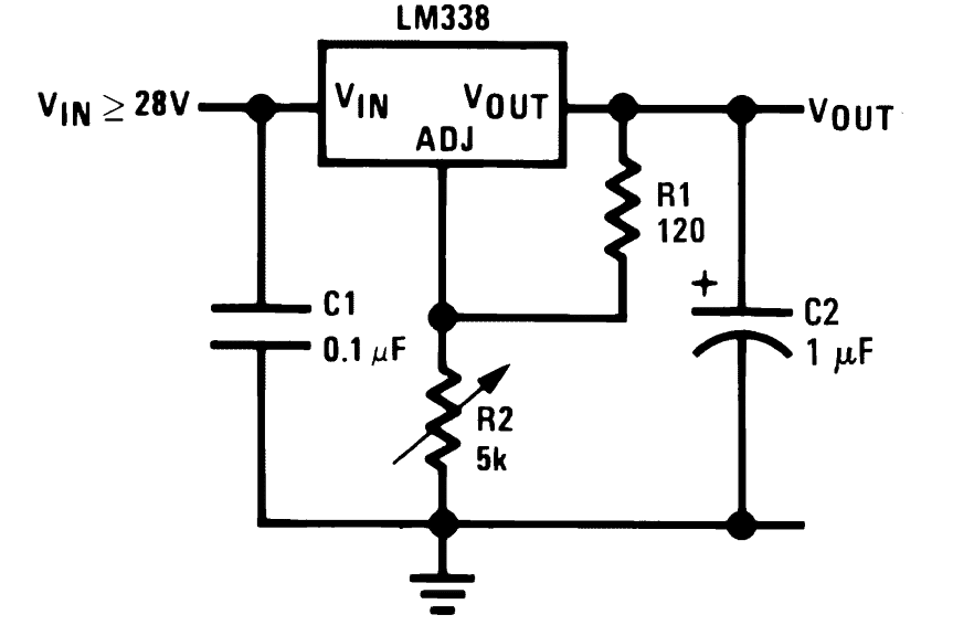
Varying the 5k pot enables setting of any desired constant voltage across the C2 capacitor (Vout) which can be used for charging a connected battery across these points.
For fixed voltage you could replace R2 with a fixed resistor, using this formula:
VO = VREF (1 + R2 / R1) + (IADJ × R2)
Where VREF is = 1.25
Since IADJ is too small it can be ignored
Although a constant voltage may be necessary, in places where the voltage from an input AC mains does not vary too much (a 5% up/down is quite acceptable) one may entirely eliminate the above circuit and forget about the constant voltage factor.
This implies that we can simply use a correctly rated transformer for charging a battery without considering a constant voltage condition, provided the mains input is fairly dependable in terms of its fluctuations.
Today with the advent of SMPS devices, the above issue completely becomes immaterial since SMPS are all constant voltage power supplies and are highly reliable with their specs, so if an SMPS is available, the above LM338 circuit can be definitely eliminated.
But commonly an SMPS comes with a fixed voltage, so in that case customizing it for a particular battery might become an issue and you may have to opt for the versatile LM338 circuit as explained above.... or if you still want to avoid this, you may simply modify the SMPS circuit itself for acquiring the desired charging voltage.
The following section have explained the designing of a customized current control circuit for a specific, selected battery charger unit.
Adding a Constant Current
Just like the "constant voltage" parameter, the recommended charging current for a particular battery should not be increased or fluctuated by much.
For lead acid batteries, the charging rate should be approximately 1/10th or 2/10th of the printed Ah (Ampere Hour) value of the battery. meaning if the battery is rated at say 100Ah, then its charging current (amp) rate is recommended to be at 100/10 = 10 Ampere minimum or (100 x 2)/10 = 200/10 = 20 amp maximum, this figure should not be increased preferably to maintain healthy conditions for the battery.
However for Li-ion or Lipo batteries the criterion is entirely different, for these batteries the charging rate could be as high as their Ah rate, meaning if the AH spec of a Li-ion battery is 2.2 Ah then it's possible to charge it at the same level that is at 2.2 ampere rate Here you don't have to divide anything or indulge in any kind of calculations.
For implementing a constant current feature, again a LM338 becomes useful and can be configured for achieving the parameter with a high degree of accuracy.
The below given circuits show how the IC may be configured for implementing a current controlled battery charger.
Make sure to check out this article which provides an excellent, and highly customizable battery charger circuit.
Schematic for CC and CV Controlled Battery Charger
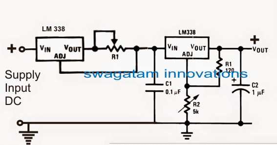
As discussed in the previous section, in case your input mains is fairly constant, then you can ignore the right hand side LM338 section, and simply use the left side current limiter circuit with either a transformer or an SMPS, as shown below:
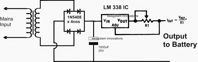
In the above design, the transformer voltage may be rated at the battery voltage level, but after rectification it might yield a little above the specified battery charging voltage.
This issue can be neglected because the attached current control feature will force the voltage to automatically sink the excess voltage to the safe battery charging voltage level.
R1 can be customized as per the needs, by following the instructions furnished HERE
The diodes must be appropriately rated depending on the charging current, and preferably should be much higher than the specified charging current level.
Customizing current for charging a battery
In the above circuits the referred IC LM338 is rated to handle at the most 5 amps, which makes it suitable only for batteries upto 50 AH, however you may have much higher rated batteries in the order of 100 AH, 200 AH or even 500 AH.
These might require charging at the respective higher current rates which a single LM338 might not be able to suffice.
To remedy this one can upgrade or enhance the IC with more ICs in parallel as shown in the following example article:
In the above example, the configuration looks little complicated due to the inclusion of an opamp, however a little tinkering shows that actually the ICs can be directly added in parallel for multiplying the current output, provided that all the ICs are mounted over a common heatsink, see the below diagram:
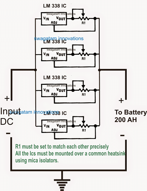
Any number of ICs may be added in the shown format for achieving any desired current limit, however two things must be ensured in order to get an optimal response from the design:
All the ICs must be mounted over a common heatsink, and all the current limiting resistors (R1) must be fixed with a precisely matching value, both the parameters are required to enable an uniform heat sharing among the ICs and hence equal current distribution across the output for the connected battery.
So far we have learned regarding how to customize constant voltage and constant current for a specific battery charger application.
However without an auto cut-off a battery charger circuit may be just incomplete and quite unsafe.
So far in our battery charging tutorials I have explained how to customize constant voltage parameter while building a battery charger, in the following sections I will try to explain how to implement a full charge auto cut off for assuring a safe charging for the connected battery.
Adding an Auto-Cut 0ff in Battery Charger
In this section we'll discover how an auto cut-off may be added to a battery charger which is one of the most crucial aspects in such circuits.
A simple auto cut-off stage can be included and customized in a selected battery charger circuit by incorporating an opamp comparator.
An opamp may be positioned to detect a rising battery voltage while it's being charged and cut off the charging voltage as soon as the voltage reaches the full charge level of the battery.
You might have already seen this implementation in most of the automatic battery charger circuits so far published in this blog.
The concept may be thoroughly understood with the help of the following explanation and the shown circuit GIF simulation:
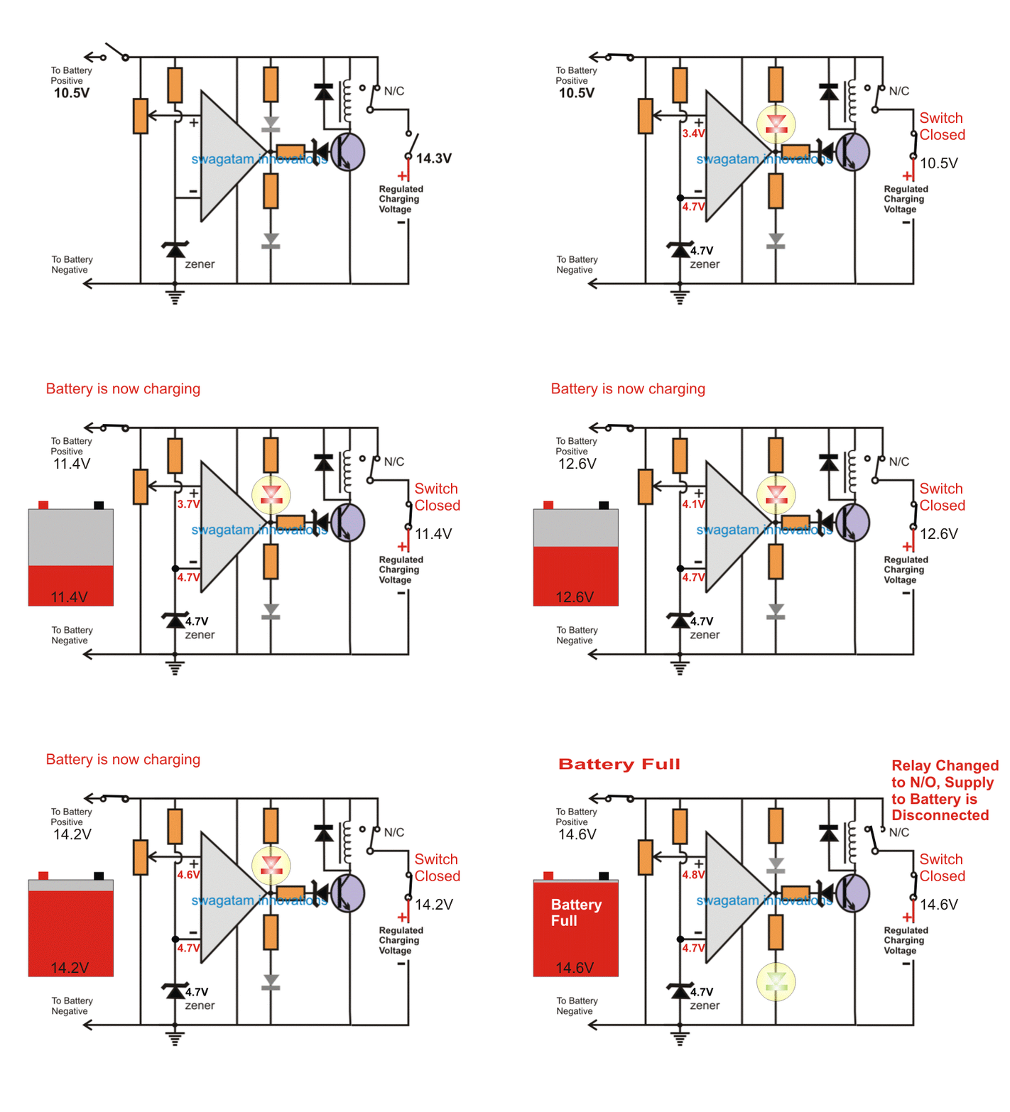
NOTE: Please use the relay N/O contact for the charging input, instead of the shown N/C. This will ensure that the relay does not chatter in the absence of a battery. For this to work, also make sure to swap the input pins (2 and 3) with each other.
In the above simulation effect we can see that an opamp is been configured as a battery voltage sensor for detecting the over charge threshold, and cutting off the supply to the battery as soon as this is detected.
The preset at pin (+) of the IC is adjusted such that at full battery voltage (14.2V here), the pin#3 acquires a shade higher potential than the pin (-) of the IC which is fixed with a reference voltage of 4.7V with a zener diode.
The previously explained "constant voltage" and "constant current" supply is connected to the circuit, and the battery via the N/C contact of the relay.
Initially the supply voltage and the battery both are switched off from the circuit.
First, the discharged battery is allowed to be connected to the circuit, as soon as this is done, the opamp detects a potential that's lower (10.5V as assumed here) than the full charge level, and due to this the RED LED comes ON, indicating that the battery is below the full charge level.
Next, the 14.2V input charging supply is switched ON.
As soon as this is done, the input instantly sinks down to the battery voltage, and attains the 10.5V level.
The charging procedure now gets initiated and the battery begins getting charged.
As the battery terminal voltage increases in the course of the charging, the pin (+) voltage also correspondingly increases.
And the moment the battery voltage reaches the full input level that is the 14.3V level, the pin (+) also proportionately attains a 4.8V which is just higher than the pin (-) voltage.
This instantly forces the opamp output to go high.
The RED LED now switches OFF, and the green LED illuminates, indicating the changeover action and also that the battery is fully charged.
However what may happen after this is not shown in the above simulation. We'll learn it through the following explanation:
As soon as the relay trips the battery terminal voltage will quickly tend to drop and restore to some lower level since a 12V battery will never hold a 14V level consistently and will try to attain a 12.8V mark approximately.
Now, due to this condition, the pin (+) voltage will again experience a drop below the reference level set by pin (-), which will yet again prompt the relay to switch OFF, and the charging process will be again initiated.
This ON/OFF toggling of the relay will keep on cycling making an undesirable "clicking" sound from the relay.
To avoid this it becomes imperative to add a hysteresis to the circuit.
This is done by introducing a high value resistor across the output and the (+) pin of the IC as shown below:
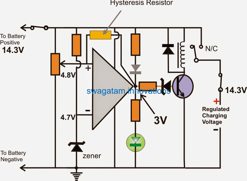
Adding Hysteresis
The addition of the above indicated hysteresis resistor prevents the relay oscillating ON/OFF at the threshold levels and latches the relay up to a certain period of time (until the battery voltage drops below the sustainable limit of this resistor value).
Higher value resistors provide lower latching periods while lower resistor provide higher hysteresis or higher latching period.
Thus from the above discussion we can understand how a correctly configured automatic battery cut-off circuit may be designed and customized by any hobbyist for his preferred battery charging specs.
Now lets see how the entire battery charger design may look including the constant voltage/current set up along with the above cut-off configuration:
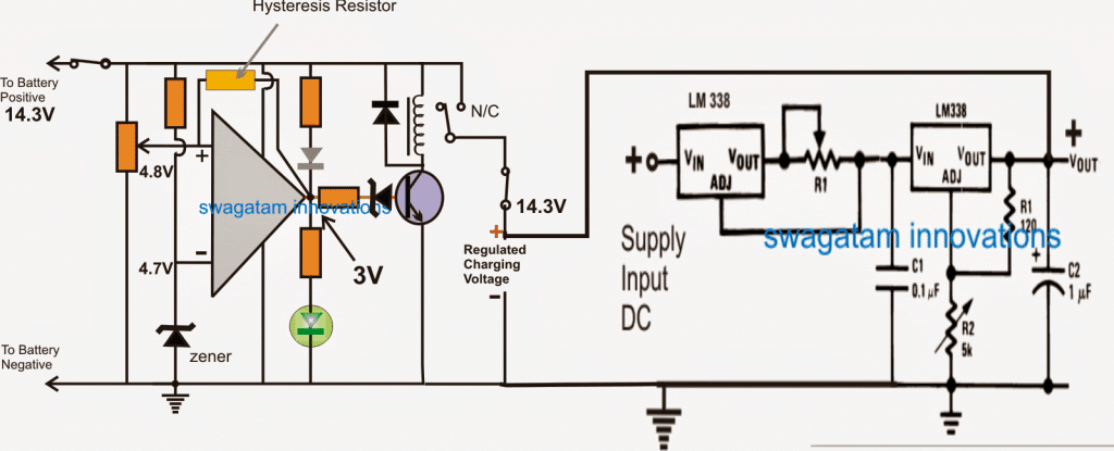
So here's the completed customized battery charger circuit which can be used for charging any desired battery after setting it up as explained in our entire tutorial:
- The opamp can be a IC 741
- The preset = 10k preset
- both zener diodes can be = 4.7V, 1/2 watt
- zener resistor = 10k
- LED and transistor resistors can be also = 10k
- Transistor = BC547
- relay diode = 1N4007
- relay = select match the battery voltage.
How to Charge a Battery without any of the Above Facilities
If you are wondering whether it is possible to charge a battery without associating any of the above mentioned complex circuits and parts?
The answer is yes, you can charge any battery safely and optimally even if you do not have any of the above mentioned circuits and parts.
Before proceeding it would be important to know the few crucial things a battery requires to charge safely and the things that make "auto cut off" "constant voltage" and "constant current" parameters so important.
These features become important when you want your battery to be charged with extreme efficiency and quickly. In such cases you may want your charger to be equipped with many advanced features as suggested above.
However if you are willing to accept the full charge level of your battery slightly lower than optimal, and if you willing to provide a few hours more for the charging to finish, then certainly you wouldn't require any of the recommended features such as constant current, constant voltage or auto cut off, you can forget all these.
Basically a battery should not be charged with supplies having higher rating than the battery's printed rating, it is as simple as that.
Meaning suppose your battery is rated at 12V/7Ah, ideally you must never exceed the full charge rate above 14.4V, and current over 7/10 = 0.7 amps.
If these two rates are correctly maintained, you can rest assured that your battery is in safe hands, and will never get harmed regardless of any circumstances.
Therefore in order to ensure the above mentioned criteria and to charge the battery without involving complex circuits, just make sure the input supply that you are using are rated accordingly.
For example if you charging a 12V/7Ah battery, select a transformer which produces around 14V after rectification and filtration, and its current is rated at around 0.7 ampere.
The same rule may be applied for other batteries also, proportionately.
The basic idea here is to keep the charging parameters slightly lower than the maximum permissible rating.
For example a 12V battery may be recommended to be charged upto 20% higher than its printed value, that is 12 x 20% = 2.4V higher than 12V = 12 + 2.4 = 14.4V.
Therefore we make sure to keep this slightly lower at 14V, which may not charge the battery to its optimal point, but will be just good for anything, in fact keeping the value slightly lower will enhance the battery life allowing many more charge/discharge cycles in the long run.
Similarly, keeping the charging current at 1/10th of the printed Ah value makes sure that the battery is charged with minimum stress and dissipation, rendering a longer life to the battery.
The Final Setup
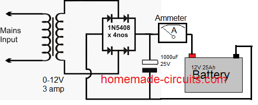
A simple set up shown above can be universally used for charging any battery safely and quite optimally, provided you allow sufficient charging time or until you find the needle of the ammeter dropping down to almost zero.
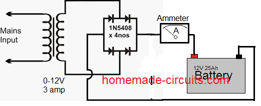
The 1000uf filter capacitor is actually not needed, as shown above, and eliminating it would actually enhance the battery life.
Have further doubts? Do not hesitate to express them through your comments.
Source: battery charging


Questions & Answers
Hi sir,
Your blog is very much interesting.
Sir I need some help to build CONSTANT VOLTAGE OUTPUT,
As I have 1kw alternator, It gives 0-50vdc output, but it's fluctuating & will be varied from 0 to 50vdc….I need constant voltage for battery charger, so that I can connect FAST BATTERY CHARGER CIRCUIT to that output…..Can I use LM338?………Please suggest me. Your help will be very HELPFUL.
THANK YOU
Thanks Kaustubh,
LM338 will take not more than 38V at the input, so it might not be possible to use this IC.
You can try using the following voltage regulator concept and see the response….you can reduce the number of transistors as per your amp requirement:
https://www.homemade-circuits.com/2015/03/100-amp-variable-voltage-power-supply.html
Dear Sir,
I have recently purchased 2pcs of 6V 4.5Ah SLA and 1pc of 12V 12Ah battery but currently i am not using them.
I will be using them in the near future as and when i need them.
I don't want the newly purchased batteries to self discharge, so i wish to keep them on continuous charging system i.e., 24Hrs non-stop.
What i wanted to know was how much current and at what voltage should i need to apply continuously on the batteries?
Also is a continuous charging system dangerous to the battery OR one can implement it freely without any issues?
Thanks
Hi Sherwin,
to keep the battery healthy you can keep it trickle charged using an automatic battery charger.
you can charge it at a constant current rate which may be at 1/10th of its AH rating and then float charge it with a 1/50th AH rate…. this figure is not too critical but lower current is preferred for the float charge.
HI sir,
i want to ask that some other topic’s question.”To get 2amp power output can i use two lm7805 in parallel in circuit?”
Hi Abhishek , it is possible, just make sure to attach them both over a single common heatsink.
Hello
I would like know, if I can do a charger circuit for battery lipo just with a CI LM337 with current constant.
and a AMPOP, how voltage comparator para turn off when to be 4.2V
I would like let my circuit without voltage constant because i know that only current constant the CI lM317 do this to work voltage regulator for the current.
I would like know if is possible charger battery lipo this way ?
Best Regard
congratulation for blog perfect in subject.
Hello, yes definitely you can build a Li-po battery charger using a simple LM317 circuit as shown below,
https://www.homemade-circuits.com/how-to-make-current-controlled-12-volt/
however make sure to adjust the output of the LM317 to 4.1V and not 4.2V, this will never allow your battery to become fully charged, and safeguard it from over charge.
Thank you for the answer.
Just for confirm your answer. I have a littel doubet that cause a confusion in my understand.
When you say adjust output for 4.1V, you say adjust the LM317 for this output or adjust the cut AMPOP for 4.1V.
Because always in circuit when seen in internet is build with current and voltage constant. Setuping first LM317 how constant current and second LM317 how constant voltage.
I would like eliminet the second LM317 with constant output, and let this job all to the first LM317 that control current e voltage. And who will control the cut output is AMPOP.
thank you
4.1 V should be adjusted using the LM317 preset to get a constant 4.1V out for the battery, please see the first diagram in the link which I referred, it has only a single LM317 IC based design, with a BC547 stage for the current control
please can help me with comprehensive design and construction of four level automatic battery charger incorporating a digital progress indicator that is capable of charging a 12v,24v,36v and 48volt design analysis and circuit design .
Hello
I would like know if is possible regulate voltage and current just with one lm317.
Example. I would like 4.2V just with 150mA.
I cant to place 2 regulator because cost project will be stay very heigh. So for me is very import know if this is possible.
Best Regards
Hi, yes that’s definitely possible, you can refer to the following article for the details:
https://www.homemade-circuits.com/how-to-make-current-controlled-12-volt/
Hello sir Swagatam,
Thank you so much for the published article. I have few questions:
I want to use the schematic to charge four 7AH batteries connected in parallel, which gives a total of 28AH.
1. How do I set R1 to match the correct output current which is about 2.8A? If I want use fixed resistor for R1, how do I make the calculation?
2. If I want use a fixed resistor for R2, how do I make the calculation in order to achieve 14.8V, which is the required voltage for charging?
3. What is the function and value of the zener diode connected to BC547?
4. Can I use LM358N as the opamp?
5. Will the two LM338 require heat sinks for the said purpose?
6. How do I calculate the value of the hysteresis resistor for the said purpose?
Anticipating your usual prompt response. Thank you sir.
Thanks Godson, for a 28 AH battery, you can set
R1 = 1.25 / 3 = 0.41 ohme, 5 watts
for R2 you can try the following software
https://www.homemade-circuits.com/lm317-lm338-lm396-calculator-software/
the zener is used to prevent leakage voltage from opamp output to get into the transistor base, instead of zener you can use a 1K resistor across base/emitter
you can use any other opamp, all will work, LM321 can also be tried
for calculating hysteresis resistor you can study the following article
https://www.homemade-circuits.com/universal-battery-charger-circuit/
Hello sir Swagatam,
Thanks a lot for the reply. Regarding using fixed resistors for R2, what will be the power rating of the resistor? What will be the power rating of the 120ohm resistor connected between the “output” and the “adjust” pins of th LM338?
Hello Godson, whenever it is not specified, it is always 1/4 watt CFR or MFR, CFR will be cheaper.
Hello sir Swagatam,
Thanks a lot for the reply. Please I would like you to help me with the following info:
1. If I want to obtain 12V from a 12V transformer based power supply, can I simply connect a 12V zener diode across the filter capacitor? I want to use it to run the cooling fan for my inverter which is rated 12V DC.
2. I need a schematic diagram of a transformerless power supply that can conveniently run an IC and can deliver between 100mA and 200mA.
Your reply will be appreciated sir.
Hello Godson,
the zener will burn and create a short circuit if the input is from a transformer because the transformer will have much higher current than the zener rating, a series resistor can be used with the supply to prevent but that would also reduce the current output to a very low level, insufficient for the fan.
the correct way would eb to use a 7812 IC, or a transformerless power supply will also work, but will not be isolated from mains and may cause fatal electric shock if touched in powered condition.
you can try the following design:
https://www.homemade-circuits.com/cheap-yet-useful-transformerless-power/
use 5uF/400V for C1, use 5 watt zener (1N5349B) for the zener, and replace the 50 ohm with a 22 ohm resistor
Hello sir swagatam , i made the circuit but when i connect my battery to the circuit it does not charging showing but voltage across battery terminal is same as applied , i did not decrease .
1. what does it mean?
2. Is my ciruit wrong ? If it is then what should it do to correct it? and
3.Iam unable increase my voltage regulator output to applied voltage
i.e.,if i apply 12v at input iam getting maximum of 7 volts output (by changing the 5k pot).
Hello Kranthi,
Please use a 10K pot, and set the output to 14V, and for this you will need an input of at least 18V.
Please do this and check the response again.
When you connect the output with your battery, the voltage must immediately drop to the battery’s existing voltage level, and then begin rising slowly as the battery charges.
and Make sure to select the current control resistor correctly.
If you are using a transformer or the input supply source with a current rating 1/10th of your battery Ah, in that case the current control stage can be eliminated….
thank you in advance
sir i have a cpu power stage that i tweak it setting to produce (+18v %-18 volt ) instead of (+12v & -12 volt) but i want the negative output to be (-9 volt ) in stead of (-18 volt) please can you kindly refer me to a circiut i to use it as a dc to dc converter for the gate driver circiut to drive igbt for electric car
And sir i think BD140 and BD139 is capable of 3 or 2amps is there any transistor that that as the similarities of BD140 and BD139 but can give up to 6 or 5amps
Abioye, may be you can try adding the following circuit, but preferably use a pot instead of the shown rotary switch
https://www.homemade-circuits.com/dual-power-supply-3v5v6v9v1215v-with/
for 2/3 amp it is better to go for TIP31/32 transistors, BD139/140 will not be able to handle that much current
sir thanks for cheering your precious time with me, but is 3amps enough for the gate of a 600v 1200 amps igbt assuming i use the tip31 and tip32 you recommended for me sir for switching the igbt on and off fast or sir can you direct me to any efficient and simple igbt gate driver for novice like me
Abioye, IGBT gates do not require high current to operate, just like mosfets they too can work with minimal current across their gate/emitter, but they are better than mosfets because they can be operated with minimal voltages also, and have lower On time resistance than mosfets
Hello,
I am planning to charge a 12V lead acid battery with your circuit.
I have tried your circuit in a bread board ,but it had some problems.
First off all,what is the value of hysteris resistor i need to again start auto charging when the battery charge becomes, say 30%.??
And as shown in the above simulation the red led doesnot light up. Only the green lights up all the time.
And at what value should i set the 10k preset to charge 12V lead acid battery.?
hysteresis resistor will need to be found through trial and error by experimenting with different resistors and increasing or decreasing the values proportionately until the right cut off is achieved.
you can change the LED positions as shown in the following diagram for correct response, because IC 741 is not an efficient opamp and has a large offset voltage which may keep the green LED permanently On,
https://www.homemade-circuits.com/make-6v-4ah-automatic-battery-charger/
initially keep the 10K preset at pin#3 of the opamp to ground, switch ON input power, adjust the the LM338 pot to 14.3V, and finally next adjust the 10K preset until the green LED just lights up, this will set the upper full charge cut off.
remember to remove the green LED from the shown position and place in series with the transistor base or you can also replace it with the base zener of the transistor
Hi swag..
I have 12v 6ah and 5amp trasnformer along with lm317 set to 14.2v
How to know if the battrery is fully charged?
Thanks.
Hi Candra, limit the current to 600mA, and voltage to 14V, and keep the charger connected. Occasionally check the voltage across the battery terminals, when it reaches 14V , you can consider it almost fully charged.
thanks..
looking at your lm338 current limiter what is value for R1?
candra, you can refer to this article for the details:
https://www.homemade-circuits.com/universal-high-watt-led-current-limiter/
how to be a current variable rather than fixed?
for example from low to 3A max current
thanks.
you can change the resistor values or use a pot in its place for changing the range
Iout = Vref/R1 thats mean R1 could not be zero am I right? or is there any explanation
thanks.
yes it cannot be zero, because any conductor will have some resistance
What if R1 is removed? Or it should not be omitted? Because if i use pot at max that’s mean R1 will 0 or no resistance between out and adj?
Theoretically R1 can be never zero. As I said previously, even a shorted R1 will have some resistance, it could be in 0.00000xyz but it will have some value.
it means even if R1 is 0.00000xyz max current will around 5A?
yes that’s what we are supposed to get if there’s hardly any resistance, we’ll have the full current from the source.
ok. thanks swag
I’ve just figured it out…
Greetings dear Swang,
I have sought to study your topics very well, very well oriented here. But some things still have difficulties. If you can help me, I’ll be very grateful again.
I have a solar panel Power (NP): 20; Νmax (v): 17.90; Im (A): 1.24; Voc (V): 21.76; ISC (A): 1.32; Efficiency (%): 11.1; Cell Type: Polycrystalline; Number of cells per module: 36.
And 3 small of 6V / 1W.
1 PMW 12V / 10A charge controller
1 Stationary 12V / 12 Ah lead acid battery, 18 cells 1.2V NiCd, some 18650 and several 3.7V Li-ion batteries.
I do not have a power grid, but my consumption is little. Only lighting, sound and smartphone.
I would like to maximize what I have.
This custom charger circuit using the LM 338, LM 741 and BC 547 seemed to me quite versatile and fit my design given the variety of my batteries. Am I right?
* I intend to acquire more powerful solar panels
1º – As the current need would be low, can I replace the LM338 with the LM317?
2 – Can I use the LM833 (which I have in the trash) instead of the LM741?
3º – With the configuration of this circuit I could work in the range of 6V up to 12V?
4º – In this range from 6V to 12V, if possible, what would the hysteresis resistor look like? Could it replace with a variable resistor of 1K?
5 – Could R1 be a variable resistor of 1K? (I have many)
6th – A 6V relay could work with batteries in series forming 12V?
7th Later, if more current is needed, can I add a TIP42C in BYPASS?
I suppose my doubts must be tiresome to you, but to me your lessons are treasures.
Very good sir.
Thank you Dear Marcelo, for reading my articles so keenly.
Yes definitely you can use the LM338 and the op amp based circuit for your application, although it won’t give the kind of efficiency a buck converter based design would give. Nevertheless, since the design is much simpler than a buck converter, I would recommend this design.
You can use LM833, but to fix the hysteresis resistor you may require some trial and error operations. You can start with 1K, and check at what lower voltage the relay clicks back, and in this way you can increase a bit and check again, to finally set the right threshold.
LM317 can be used instead of LM338 if the battery Ah rating is less than 10 Ah.
A 6V relay can be used to charge two 6V batts in series but separately, one by one.
For more current I would recommend using LM338, because adding an an outboard transistor may required some calculations and adjustments.
Many thanks for your time dear Swag,
But my English is not very good and in the translation of google a part I do not know if I understood. In the use of 6V relay, would you have to use a relay for each 6V battery connected in series?
OK understood, you can use a single 6V relay for charging the two batteries, but it cannot be charged together, you will have to charge them one by one separately…or use a 12V relay to charge the series with 14V together.
Good morning dear Swag and thanks for the clarifications.
Still breaking his head around here. Trying to make an arrangement with what I have, what I need, and what I know.
As I know little, I need your help again.
Since I have low power panels (6v / 1w), would it be possible to connect 2 of these panels in parallel, to increase the current produced and be able to charge 5 cells of 1.2v / 1000mAh NiCd connected in series?
If so, which circuit would you recommend? I have the 555, LM317, BC547, TIP 31, 41 and 42, LM833, LM431 and some mosfets.
I thought of this circuit here, as I told you, but I do not know if it compensates in this arrangement with low power panels.
Thanks in advance for your kind help
PS. Can I use the Shottky 1N4148 diode to protect these panels?
Good Morning Marcelo,
Charging 5 cells may not be possible. Even if you add one more panel, the total wattage will be 2 watts, dividing this with 6 gives 0.33 amps, which may be just sufficient for charging 4 cells in series. At his minimal rate you won’t require any charge controller…you can just put one 1N4007 diode in series with panel and start charging the 4 cells in series….optionally you can connect an ammeter in series with the positive line to check when the meter reads zero, which will mean the cells are fully charged.
Very thankful Lighted Swag.
Your information always brings knowledge. Is the supplied amperage also divided equally into a parallel connected load?
With a panel of 6v / 3w and three of 6v / 1w each I could connect in parallel and serial respectively, without damage to them to generate 12v / 3w?
Is not the use of Schottky diodes (for less loss) a necessary protection for the panel, since its loss is less than that of silicon diodes?
Just a single diode in a serial or parallel arrangement, or one diode per panel?
Once again I thank you for your goodwill and wisdom for sharing your knowledge. May there always be light in your ways.
A big hug.
Thanks Marcel,
Yes you can connect 3 nos 6V/1 watt in parallel and connect this parallel combination in series with the 6V 3 watt panel.
Diodes hardly drop 0.7V, so if you want to save this 0.7V then you can use a Schottky diode.
For the 12V series panel, you connect just one diode with the positive line of the panel.
Wish you all the best! 🙂