In this post I will explain you all the simple formulas, step by step, which you can use for designing and building professional grade 220V AC SMPS flyback converter circuits. As we know the SMPS transformer is the heart of an SMPS design, so here we will learn all the steps, one by step, using the example of a 220V to 12V. 5 Amp, 60 watt SMPS converter, as the benchmark design. Using these same steps you can configure and design the ferrite transformer for any customized 220V or 120V AC input flyback SMPS converter circuit.
To begin with, let us consider the following parameters that must be gathered to start the calculations, and we can easily get all these from our intended SMPS specifications and the component datasheets.
Audio/Video Representation
Initial Parameters Required for Designing SMPS Flyback Transformer
- Input Voltage (Vin): 310 Volts DC
- Output Voltage (Vout): 12 Volts DC
- Output Current (Iout): 5 Amps
- Output Power (Pout): 12 Volts * 5 Amps = 60 Watts
- Estimated Efficiency (Eff): 85% (0.85)
- Input Power (Pin): Pout / Eff = 60 / 0.85 = 70.6 Watts
- Switching Frequency (f): 100,000 Hertz (100 kHz)
- Chosen Reflected Voltage (Vor): 100 Volts
- Diode Forward Drop (Vd): 0.7 Volts
- Core Effective Area (Ae): 120 square millimeters (0.00012 square meters)
- Maximum Flux Density (Bmax): 0.2 Tesla (200 millitesla)
Now let's proceed step by step and learn all the detailed formulas and calculations required for making any customized SMPS flyback converter.
Step 1: Calculate the Realized Operating Duty Cycle (D)
When we choose the reflected voltage upfront, the operating duty cycle is automatically fixed by the balance of the input voltage and the reflected voltage.
Formula: Operating Duty Cycle = Vor / (Vin + Vor)
Calculation: 100 / (310 + 100) = 100 / 410 = 0.244
Result: Operating Duty Cycle = 24.4%
Step 2: Calculate the Primary Inductance (Lp)
Formula: Primary Inductance = (Vin * Operating Duty Cycle) squared / (2 * Pin * f)
Calculation: Vin * Operating Duty Cycle = 310 * 0.244 = 75.64 75.64 squared = 5,721.4 2 * Pin * f = 2 * 70.6 * 100,000 = 14,120,000 Primary Inductance = 5,721.4 / 14,120,000 = 0.000405 Henry
Result: Primary Inductance = 405 microhenries
Step 3: Calculate the Peak Primary Current (Ipk_primary)
Formula: Peak Primary Current = (Vin * Operating Duty Cycle) / (f * Primary Inductance)
Calculation: Vin * Operating Duty Cycle = 310 * 0.244 = 75.64 f * Primary Inductance = 100,000 * 0.000405 = 40.5 Peak Primary Current = 75.64 / 40.5 = 1.87 Amps
Result: Peak Primary Current = 1.87 Amps
Step 4: Calculate the Transformer Turns Ratio (Nps)
Formula: Turns Ratio = Vor / (Output Voltage + Diode Drop)
Calculation: Output Voltage + Diode Drop = 12 + 0.7 = 12.7 Volts Turns Ratio = 100 / 12.7 = 7.87 (Let's round this to a practical, clean integer ratio of 8)
Result: Turns Ratio = 8 (Meaning you need 8 primary turns for every 1 secondary turn).
Step 5: Calculate the Primary Turns (Np)
Now we find out how many physical turns are needed on the primary winding so that the core safely handles 1.87 Amp peak current without saturating.
Formula: Primary Turns = (Primary Inductance * Peak Primary Current) / (Bmax * Ae)
Calculation: Primary Inductance * Peak Primary Current = 0.000405 * 1.87 = 0.000757 Bmax * Ae = 0.2 * 0.00012 = 0.000024 Primary Turns = 0.000757 / 0.000024 = 31.54 turns
Result: Primary Turns = 32 turns...
Step 6: Calculate the Secondary Turns (Ns)
With our primary turns rounded to 32 and our turns ratio set to 8, finding the secondary turns is easy.
Formula: Secondary Turns = Primary Turns / Turns Ratio
Calculation: Secondary Turns = 32 / 8 = 4 turns
Result: Secondary Turns = 4 turns
Step 7: Calculate the Peak Secondary Current (Ipk_secondary)
Formula: Peak Secondary Current = Peak Primary Current * Turns Ratio
Calculation: Peak Secondary Current = 1.87 * 8 = 14.96 Amps
Result: Peak Secondary Current = 15 Amps
Step 8: Calculate the RMS Currents for Wire Sizing
The primary runs at a 24.4% duty cycle, while the secondary runs during the remainder of the cycle which we call Doff.
Doff is calculated as: 1 - 0.244 = 0.756 (or 75.6% of the cycle)
Formula for Primary RMS Current: Primary RMS Current = Peak Primary Current * square root of (Operating Duty Cycle / 3)
Calculation: 0.244 / 3 = 0.0813 Square root of 0.0813 = 0.285 Primary RMS Current = 1.87 * 0.285 = 0.53 Amps
Formula for Secondary RMS Current: Secondary RMS Current = Peak Secondary Current * square root of (Doff / 3)
Calculation: 0.756 / 3 = 0.252 Square root of 0.252 = 0.502 Secondary RMS Current = 15 * 0.502 = 7.53 Amps
Result: Primary RMS Current = 0.53 Amps Secondary RMS Current = 7.53 Amps
Step 9: Final Wire Area Selection
Using your recommended current density of 4.5 Amps per square millimeter:
Formula for Primary Wire Area:
Primary Wire Area = Primary RMS Current / 4.5 Calculation: 0.53 / 4.5 = 0.118 square millimeters (Standard 26 AWG wire fits this target perfectly).
Formula for Secondary Wire Area:
Secondary Wire Area = Secondary RMS Current / 4.5 Calculation: 7.53 / 4.5 = 1.67 square millimeters (This can be nicely handled by winding 4 parallel strands of 22 AWG wire together).
Circuit Diagram
We can use the following basic IC 555 based SMPS circuit diagram for the above calculated ferrite transformer by adjusting the PWM duty cycle of the IC 555 to 24%.
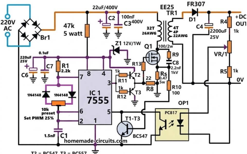
Complete Bill of Materials (BOM)
Resistors
| Reference | Value | Rating |
|---|---|---|
| R1 | 2.2k | 1/4W |
| R4 | 1k | 1/4W |
| R5 | 1k | 1/4W |
| R8 | 22Ω | 1/4W |
| R9 | 100Ω | 2W |
| R10 | 100Ω | 1/2W |
| R11 | 1k | 1/4W |
| R12 | 1k | 1/4W |
| R13 | 1k | 1/4W |
| Rs | 0.47Ω | 5W |
| Startup Resistor | 47k | 5W |
| VR1 | Preset Pot | Value not shown (typically 10k) |
| PWM Preset | 10k | Trimmer |
Capacitors
| Reference | Value | Voltage |
|---|---|---|
| C1 | 1.5nF | 100V or above |
| C2 | 22µF | 400V |
| C3 | 100nF | 400V |
| C4 | 2200µF | 25V |
| C6 | 220µF | 25V |
| C7 | 0.1µF | 50V |
| C8 | 2.2nF | 1kV |
Semiconductors
| Reference | Part |
|---|---|
| IC1 | NE555 |
| OP1 | PC817 Optocoupler |
| D1 | FR307 Fast Recovery Diode |
| Z1 | 12V / 1W Zener |
| 1N4148 | 2 pcs |
| Br1 | 2A to 4A / 600V Bridge Rectifier |
Transistors
| Reference | Part |
|---|---|
| T1 | BC547 |
| T2 | BC547 |
| T3 | BC557 |
Power MOSFET
| Reference | Suggested Part |
|---|---|
| Q1 | 7N65, FQPF7N65, STF7N65, IRF840, or similar 650V MOSFET |
For better efficiency,:
- STF7N65M2
- 8N65
- 10N65
would be preferred.
Transformer TR1
Primary
- 32 Turns
- 26 AWG Enamelled Copper Wire
Secondary
- 4 Turns
- 4 Parallel Strands
- 22 AWG Enamelled Copper Wire
Core
- EE25 Ferrite Core
- Paper or plastic spacer air gap
Input
| Item | Specification |
|---|---|
| AC Input | 220VAC |
| Fuse | 1A Slow Blow Recommended |
| NTC | Optional 5D-9 or 5D-11 |
Output
| Parameter | Value |
|---|---|
| Voltage | 12V Adjustable |
| Current | 5A |
| Power | ≈60W |
Components I Would Upgrade
If I were building it today, then I would use:
- C2 = 47µF/400V instead of 22µF
- Q1 = 8N65 or 10N65 MOSFET
- FR307 replaced with MUR460 or UF5408
- Bridge Rectifier = 4A/600V minimum
- Output capacitor = Low ESR 2200µF/25V
This can make the supply much more reliable at the full 5A output current.


Questions & Answers
Can I make the rectifier using SM5063?
Yes, you can use it to make rectifier…