In one of my electric fence charger articles, one reader asked me something interesting. He wanted to know whether a buzzer could be made to sound whenever an animal touches the fence.
At first I was thinking about a current sensing method because that looks like the obvious way. But after looking at how electric fences actually work, I realized current is not always the best thing to watch here.
How The Circuit Works
The whole circuit can be divided into four small sections.
• High-voltage sensing network.
• LM393 comparator section.
• 555 monostable timer section.
• Buzzer output section.
High-Voltage Sampling Network
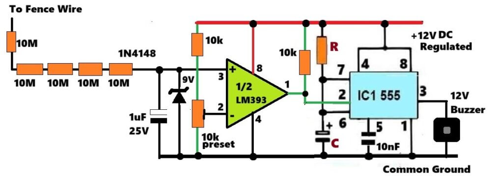
The fence wire goes to a resistor chain made from five 10 MΩ resistors connected in series. Together they become 50 MΩ
This resistance value is extremely high so the detector takes only a very tiny amount of current from the fence line. Because of that, the normal fence operation is practically not affected in any noticeable way.
For example, let us say that the fence pulse voltage is 5 kV.
I = V / R
I = 5000 / 50000000
I = 0.0001 A
I = 100 µA
So now we can clearly see that the detector is hardly loading the fence line at all. The sampled pulse then passes through the 1N4148 diode and charges the 1 µF capacitor. That diode is performing two important jobs.
First it rectifies the incoming pulse. Second, it prevents the capacitor from discharging back into the fence line between successive pulses.
So now the capacitor holds a DC voltage which follows the peak value of the fence pulses.
Zener Protection Stage
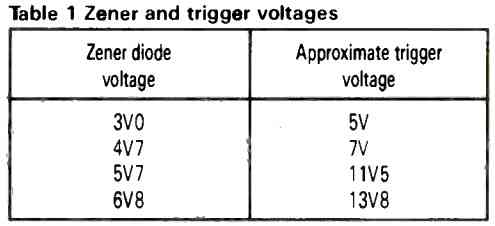
A 9 V zener diode is connected directly across the 1 µF capacitor. This zener diode prevents the capacitor voltage from rising above approximately 9 V. Without this zener diode, the capacitor voltage could slowly build up to a much higher level during no-load conditions, and then the LM393 input may receive more voltage than what we actually want.
So this small zener diode helps to keep the circuit safer and also more stable over a long period of operation.
LM393 Comparator Stage
The LM393 is working as a comparator in this circuit. The voltage stored on the 1 µF capacitor is applied to pin 3 which is the non-inverting input of the comparator. Pin 2 receives a reference voltage through the 10 k preset.
By adjusting this preset we decide the minimum acceptable fence pulse level.
Normal Fence Condition
When no animal is touching the fence then the pulse voltage remains high.
Because of that:
• The capacitor charges to a higher voltage level.
• Pin 3 remains above pin 2.
• The LM393 output transistor remains OFF.
Since the LM393 has an open-collector output, the 10 k pull-up resistor pulls the output HIGH. So now the 555 timer does not do anything and the buzzer remains OFF.
Animal Contact Condition
When an animal touches the fence, then the pulse voltage drops.
Because of this, the capacitor voltage drops, the pin 3 voltage falls, pin 3 goes below pin 2.
The LM393 immediately changes its output state. Its internal output transistor switches ON and pulls the output line directly to ground level. That falling signal is then used for triggering the 555 timer section.
555 Monostable Timer
The 555 is wired as a monostable timer. Whenever its trigger input receives a negative pulse, then it produces one output pulse whose duration depends on the values of R and C. The trigger signal comes from the LM393 output.
As soon as the comparator output goes LOW, then pin 2 of the 555 falls below one-third of the supply voltage and the timer starts operating.
Immediately pin 3 of the 555 goes HIGH and the buzzer gets energized. The ON time is according to the following standard formula:
T = 1.1 × R × C
For example:
R = 100 kΩ
C = 47 µF
T ≈ 5.2 seconds
So even though the fence pulse may exist only for a few milliseconds the buzzer can continue sounding for several seconds, and this makes the event very easy to notice.
Buzzer Operation
The buzzer is connected to the output of the 555 timer. Whenever an animal touches the fence and the pulse voltage falls below the preset level, then the timer gets triggered and the buzzer starts sounding.
After the timing period finishes, then the output returns LOW and the buzzer switches OFF automatically by itself.
Setting Up The Circuit
After assembling everything, let us do the following steps.
• Connect the sensing input to the fence wire through the 50 MΩ resistor chain.
• Power the circuit from a regulated 12 V supply.
• Adjust the 10 k preset until the circuit remains stable during normal fence operation.
• Apply a fence load or create a fence contact condition using a 10k 5 watt shunt resistor...
• Fine tune the preset until the buzzer responds only when there is a noticeable reduction in fence pulse voltage.
Concept using Current Transformer
So now this circuit watches that current increase and whenever a strong fence pulse current appears, then it switches ON a buzzer to tell us that something has touched the fence.
Circuit Operation
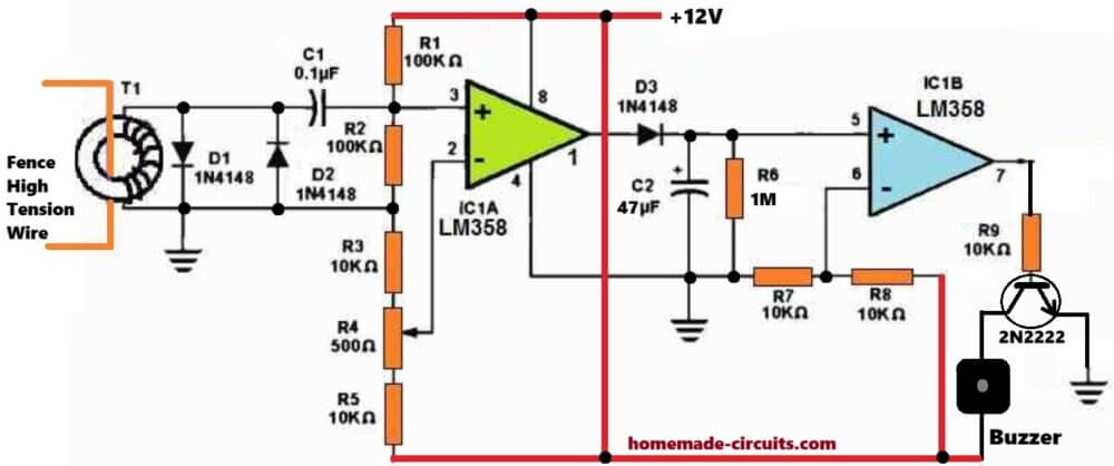
This circuit is built around LM358 and one small current transformer called T1.
The fence high tension wire is simply passed once through the center hole of the toroidal core. That itself becomes the primary winding, so there is no separate primary winding to make. Then on the same T1 core we wind a secondary coil having several hundred of wire turns and connect it with the detector circuit.
Whenever a pulse current goes through the fence wire, then a matching voltage gets induced into the secondary winding of T1.
Current Transformer Stage
T1 is actually doing the sensing job here. When fence is sitting normally, then pulse current is very small so only a weak signal appears across the secondary winding.
But when an animal touches the fence then fence current jumps up suddenly and therefore a much bigger voltage appears at the transformer secondary.
D1 and D2 are there for protection. Transformer pulses can sometimes become quite sharp so these diodes stop excessive positive and negative spikes from reaching the LM358 input.
C1 passes only the pulse signal into the non-inverting input of IC1A and blocks any unwanted DC from entering.
Signal Amplification
The first op amp section, IC1A, is used as a high gain amplifier.
R1 and R2 create a reference voltage point. R3, R4 and R5 decide the gain and switching level. R4 is the sensitivity control. If we increase it one way then circuit becomes more sensitive, if moved the other way then sensitivity reduces.
The amplified signal finally comes out from pin 1 of IC1A.
Pulse Detection and Storage
The signal from pin 1 next goes through D3. D3 rectifies the pulse and charges C2 whenever a sufficiently strong fence pulse is detected.
Fence chargers normally give only one pulse every second or around that timing, so without storage the signal would disappear between pulses. That is why we use C2. It stores the pulse energy for some time and keeps the voltage available between successive fence pulses.
R6 slowly discharges C2.
Here we have, C2 = 47 µF, R6 = 1 MΩ. So now the discharge time becomes:
T = R × C
T = 1,000,000 × 47 × 10⁻⁶
T ≈ 47 seconds
Which is quite long, so even short fence pulses can be detected properly without missing them.
Comparator Stage
The second op amp section IC1B works as a comparator. The stored voltage from C2 goes to pin 5 which is the non-inverting input. R7 and R8 create a fixed threshold voltage for the inverting input.
Whenever voltage on C2 rises above this threshold, then output of IC1B immediately goes high.
Buzzer Driver
The output from IC1B drives transistor Q1 through R9. When Q1 switches ON, then current starts flowing through the buzzer and the buzzer sounds. As long as fence current keeps producing strong enough pulses, C2 remains charged and buzzer stays active. When the animal leaves the fence, then no strong pulse current remains, so C2 slowly discharges through R6.
After some time voltage drops below the threshold and then buzzer switches OFF.
Current Transformer Construction
T1 can be made using a small ferrite toroidal core.
Typical winding details are:
- Primary: 1 turn (fence wire passing through the core)
- Secondary: 800 turns of 34 SWG enamelled copper wire
- The exact turn count is not very critical.
- Sometimes 500 turns works nicely, sometimes 1000 turns may give better sensitivity depending on the transformer core and fence conditions.
Adjustment Procedure
- Power the circuit from a regulated 12 V supply.
- Keep preset R4 roughly at the center position first.
- Run the fence charger normally.
- Now adjust R4 slowly until the buzzer remains OFF during normal fence leakage conditions.
- Next apply a test load or suitable resistor across the fence output.
- Then adjust R4 little by little until the buzzer responds only when a significant fence current is present.
Features
- Non-contact current sensing
- Complete electrical isolation from the high voltage fence wire
- Adjustable sensitivity
- Simple LM358 based design
- Suitable for battery operated fence chargers
- Audible indication whenever fence contact occurs
So now whenever an animal or any other load causes a noticeable increase in fence pulse current, then circuit detects it and gives an audible warning through the buzzer, which makes fence monitoring much easier.


Need Help? Please Leave a Comment! We value your input—Kindly keep it relevant to the above topic!