The most crucial element of a switched mode converter or an SMPS is the inductor.
Energy is stored in the form of a magnetic field in the core material of the inductor during the brief ON period (ton) switched through the connected switching element such as MOSFET or a BJT.
How the Inductor Works in SMPS
During this ON period voltage, V, is applied across the inductor, L, and the current through the inductor changes with time.
This current change is 'restricted' by the inductance, hence we find the related term choke normally used as an alternative name for an SMPS inductor, which is mathematically represented through the formula:
di/dt=V/L
When the switch is turned off, energy stored in the inductor is released or "kicked back".
Magnetic field developed across the windings collapses due to the absence of current flow or voltage to hold the field. The collapsing field at this point sharply 'cuts' through the windings, which builds a reverse voltage having an opposite polarity to that originally applied switching voltage.
This voltage causes a current to move in the same direction. An energy exchange is thus happens between the input and output of the inductor winding.
Implementing the inductor in the above explained manner can be witnessed as a primary application of Lenz's law. On the other hand, at first it seems that no energy could be stored 'infinitely' within an inductor just like a capacitor.
Imagine an inductor built using superconducting wire. Once 'charged' with a switching potential, the stored energy could possibly be held on to forever in the form of a magnetic field.
However, quickly extracting this energy can be a completely different issue. How much energy that could be stashed within an inductor is restricted by the saturation flux density, Bmax, of the core material of the inductor.
This material is usually a ferrite. The moment an inductor runs into a saturation, the core material losses its ability to get magnetized any further.
All the magnetic dipoles inside the material get aligned, thereby no more energy is able to accumulate as a magnetic field inside it. Saturation flux density of the material is generally affected with changes in the core temperature, which may drop by 50% in 100°C than its original value at 25°C
To be precise, if the SMPS inductor core is not prevented from saturating, the current through tends to become uncontrolled due to the inductive effect.
This now solely becomes limited with the resistance of the windings and the amount of current the source supply is able to provide. The situation is generally controlled by the maximum on-time of the switching element which is appropriately limited to prevent saturation of the core.
Calculating Inductor Voltage and Current
To control and optimize the saturation point, current and voltage across the inductor is thus appropriately calculated in all SMPS designs. It is the current change with time that becomes the key factor in an SMPS design. This is given by:
i = (Vin/L)ton
The above formula considers a zero resistance in series with the inductor. However, practically, the resistance associated with the switching element, inductor, as well as the PCB track will all contribute to limit the maximum current via the inductor.
Let's assume a resistance this to be a total of 1 ohm, which seems quite reasonable.
Thus the Current through the inductor can be now interpreted as:
i = (Vin / R)x (1 - e-tonR/L)
Core Saturation Graphs
Referring to the graphs shown below the first graph shows the difference in current through a 10 µH inductor with no series resistance, and when 1 Ohm is inserted in series.
The voltage used is 10 V. In case there isn't any series 'limiting' resistance, can cause the current to surge rapidly and continuously over an infinite time frame.
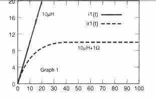
Clearly, this may not be feasible, however the report does emphasize that the current in an inductor could quickly attain substantial and potentially dangerous magnitudes. This formula merely is valid as long as the inductor remains below the saturation point.
As soon as the inductor core reaches saturation, the inductive concentration is unable to optimize the current rise. Therefore the current rises very fast which is simply beyond the prediction range of the equation. During the saturation, the current gets restricted at a value normally established by the series resistance and applied voltage.
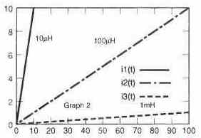
In case of smaller inductors the increases in current through them is really fast, but they can retain significant levels of energy within a stipulated timeframe. On the contrary, bigger inductor values may show sluggish current rise through, but these are unable to retain high levels of energy within the same stipulated time.
This effect can be witnessed in the second and third graphs, the former demonstrating rise in current in 10 µH, 100 µH, and 1 mH inductors when a 10V supply is utilized.
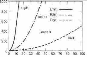
Graph 3 indicates the energy stored over time for inductors with the same values.
In the fourth graph we can see the current rise through the same inductors, by applying a 10 V although now a series resistance of 1 Ohm isinserted in series with the inductor.
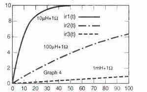
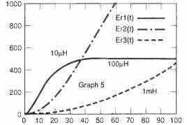
The fifth graph demonstrates the energy stored for the very same inductors.
Here, it is apparent that this current through the 10 µH inductor soars rapidly towards the 10 A maximum value in roughly 50 ms. However as a result of 1 ohm resistor it is able to retain only close to 500 millijoules.
Having said that, current through 100 µH and 1 mH inductors rises and the stored energy tend to be reasonably unaffected with the series resistance across the same amount of time.

Questions & Answers
Hello sir, I noticed the laptop smps does not have continuous charging it has a pulse charging mode, please why, is this how smps operate
Hi Dan, SMPS gives a constant DC, it does not give pulsing DC, but there’s another circuit in laptops which does the pulsing:
You are right, it looks like pulse charging, and that’s actually done purposely.
See, laptop SMPS just gives constant DC voltage (like 19V) but inside laptop there is smart charging circuit. That thing controls the battery charging.
Now modern laptop batteries are Li-ion or Li-Po and these batteries can not take continuous charging, they get hot, damaged or even blast.
So charging system gives current in small pulses. It charges for a second, then stops, checks battery condition, then charges again if needed. This is called pulse charging or intermittent charging.
It helps to keep battery cool, safe, and long lasting. So this is normal, not a fault and it is controlled by laptop, not by SMPS.
please how can I blend the design for smps flyback transformer and accompanying inductor, as I inputted the parameters into smps calculator and buck converter calculator, gave different duty cycle.
please kindly assist, sir, Engineer Swagatam?
Dan, Why do you have to use an inductor if you are using a flyback transformer, or vice versa? Use flyback transformer only if you want to have an isolation of the output DC from the input supply, otherwise just use a simple inductor.
Why the duty cycles are different? Lets check the relevant duty cycle formulas.
Buck Converter Formula: Duty Cycle D = Vout / Vin
Flyback Converter Formula: D = Vout * Np / (Vin * Ns + Vout * Np)
Flyback duty depends on transformer turns ratio because its isolated. It works in two phases: energy storage in core, and release to output.
So, Duty cycle changes depending on how you wind the transformer.Also depends on leakage inductance, core material and mode (DCM/CCM).
That is why You get different duty cycles in calculators because they are for different converter types.
Both are used here.
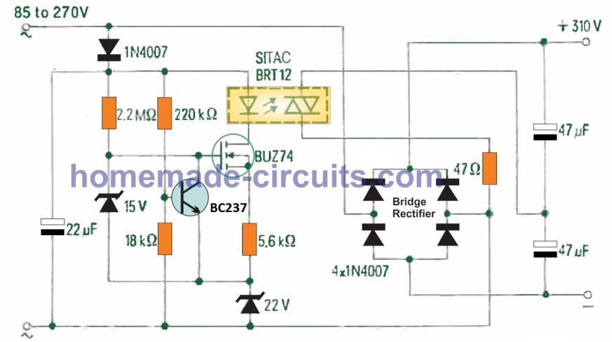
please sir, in this circuit, what is the meaning of float in upper parts, how is it interpreted?
someone said this circuit is similar and just like inverter circuit, how is it so, sir?
please sir, how is smps similar to an inverter according to an opinion?
Dan, inverter has an isolated output through a transformer, and SMPS also uses the same configuration, that is why they look similar…
I think FLOAT refers to a connection which can be either to the +310V, or ground. This float terminal cannot be kept unconnected, otherwise the transformer will not work.
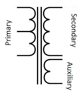
Here all the inductors different roles. Only one is used for the step-up flyback operation at the right side of the diagram using ETD59 core. There are no two inductors for boosting the inverter voltage.
Sir, please what is the function of 20uh inductor after the rectifier right side of etd59.
Those inductors are for noise and harmonics filtering.
please, just like they got 20uh inductor, is there any calculator for filtering.
You can try this:
https://www.homemade-circuits.com/inverter-lc-filter-calculator/
Thanks sir, it was useful, how will I estimate the ripple harmonics cut off.
Dan, here’s the rule of thumb formula:
fc = 3 × main frequency….. up to 10 × main frequency
so for 50Hz
fc = 150Hz to 500Hz
Currently I don’t have this calculator but will soon try to get one and post it.
please is this step up or step down, the output voltage is 50v. what is the meaning of +50 and -50v output, please how will this outputs be used in applications?
please is flyback transformer same as high frequency ferrite transformer, is it different from ferrite core inductor?
Thanks sir, Engineer Swatagam, for always willing to educate.
Dan, It seems your attached diagram is a step-down flyback buck converter. The dual 50V can be used for amplifiers or other desired applications which require a dual 50V supply.
Flyback Transformer is a type of high frequency transformer but it has special working rules.
It operates by storing magnetic energy in the core during ON time and releases it to the secondary during OFF time, just like any ordinary transformer
But we have to put air gap in the ferrite core to hold energy like an inductor, and flybacks work only with high frequency ferrite core switching.
So a flyback transformer is a transformer because it delivers the stored magnetic energy to the secondary winding during OFF periods and it is also an high frequency inductor, because it requires a ferrite core for high frequency switching to enable high efficiency.
So flyback transformer works like an iron core transformer but flyback is hugely more efficient then iron core trafos due to ferrite core high frequency switching, and therefore used in SMPS.
Hi Mr Swagatam;
Is it possible to use the primer or seconder side of a transformer as / instead of a coil?
Hi Suat, it may be possible depending upon the switching frequency…