In this post I have explained a 6 very useful yet simple ultrasonic transmitter and receiver circuit projects which can used for many crucial applications, such as ultrasonic remote control, burglar alarms, electronic door locks, and for listening to frequencies in the ultrasonic range which are normally inaudible to human ears.
Introduction
Many commercial ultrasonic gadgets work with a predetermined frequency and make use of transducers which are made to peak, or resonate, at the specific frequency. The restricted bandwidth and price of the majority of of such transducers cause them to become inappropriate for hobby and DIY implementations.
But in fact, that isn't an issue, since virtually any piezo speaker could be applied like a ultrasonic transducer for both, in the form of a transmitter output device and also as receiver sensor.
Although piezo speakers efficiency cannot be compared with the efficiency of a specialized, industrial transducer, as a hobby and fun project these can work perfectly. The device we employed with the below explained circuits was a 33/4 -inch piezo tweeter which is available from most online stores.
1) Simplest Ultrasonic Generator
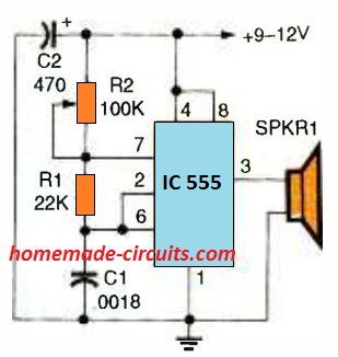
generator may be constructed without much difficulty
and very quickly.
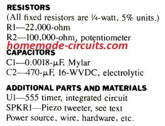
Our very first circuit, is shown in the above Fig, is an ultrasonic generator which uses the well-known 555 IC timer in a adjustable frequency astable multivibrator circuit. The design outputs a square wave signal which, works with R2, for tuning through around a frequency range of 12 kHz to over 50 kHz.
This frequency range can easily be adjusted by altering the value of capacitor C1; employing a lower value will cause the range to go higher, while larger value will make the range that much smaller.
2) Ultrasonic Generator with Fixed 50% Duty Cycle
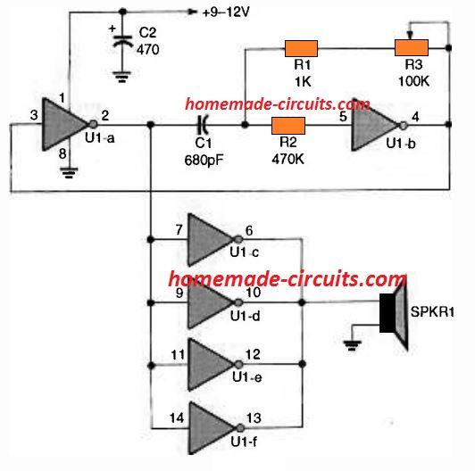
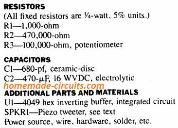
The next ultrasonic generator, revealed in the above Fig. 2, makes use of 6 buffer gates of a solitary 4049 CMOS inverting buffer IC.
A couple of the buffers, U1a and U1b, can be seen attached within a variable-frequency astable-oscillator circuit having a 50 % duty cycle, square wave output.
The rest of the 4 buffers all connected in parallel in order to enhance the output over the connected piezo element. This much better ultrasonic generator's frequency range is approximately similar to the previous IC 555 version. However, The major advantage of this design is its accurate 50% duty cycle around the full frequency range.
That said, the frequency range could be made higher by lowering the capacitor C1 value, and the frequency can be decreased by using higher values for C1. The 100k potentiometer, along with resistor R3, fixes the output frequency.
3) PLL Ultrasonic Generator
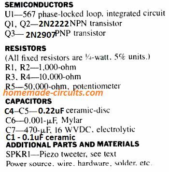
The LM567 phase-locked-loop (PLL) IC is used for generating ultrasonic frequency in our 3rd concept as proven in the above figure 3. This circuit provides a number of features better than previous two ultrasonic concepts.
First, the IC 567's in-built oscillator is developed to work within a incredibly large frequency spectrum, from under 1 Hz and as high as 500 kHz. The generator's output waveform, at pin 5, exhibits outstanding symmetry all through its performance range.
The generator additionally gives a increased output compared to other two circuits for the reason that output is matched much closely to the piezo tweeter's (SPKR1) impedance.
The output of the circuit could be tweaked through around 10 kHz to more than 100 kHz working with potentiometer R5. Transistor Q1 is hooked up like a common collector circuit in order to keep the 567's output aloof as well as to drive the output-amplifier circuit which is created using the transistors Q2 and Q3. The circuit could be changed into an ultrasonic cw transmitter by breaking the IC's pin 7 connection and inserting a switch key in series.
In that case, you will require some form of ultrasonic receiver to hear the signals; and that is the exactly what we are going to discuss in our next circuit.
4) Ultrasonic Receiver Circuits
explained LM 567 ultrasonic transmitter for best results.
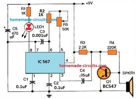
A ultrasonic receiver circuit using a 567 PLL IC that features a frequency tuning capability is shown in the above diagram. The IC's tunable oscillator circuit is identical to the earlier generator circuit, and handles exactly the same range of frequency. An LED is positioned at the pin 8 detector pin of the IC which quickly indicates the detected signals.
Transistor Q1 is positioned to amplify the minute ultrasonic signals detected by the piezo device and forwards them onto the PLL.
How to Test
To test the ultrasonic working, switch on the IC 567 ultrasonic generator circuit and move the transmitter piezo all through the area. Beginning with the minimum setting, fine-tune R5 bit by bit until you are unable to listen to anything from the speaker. This should fix the circuit's output frequency approximately to 16 and 20 kHz, depending in your ear's sensitivity to high-frequency.
Now, switch on the ultrasonic receiver circuit and position its piezo transducer at approximately 12 inches away from the generator's speaker, although having itaimed in the exact same direction. Adjust the receiver through R5, beginning from the minimum frequency point (which corresponds to the pot's maximum resistance range), and little by little maximize the frequency until yo see the receiver's LED just illuminating.
If you see receiver not responding to the transmitter output signals, try aiming the receiver's piezo accurately the generator's speaker and keep doing this persistently. As soon as the receiver detects the signal and the LED lights up, move the two Tx/Rx piezo away by a a minimum of ten feet and begin fine tuning yet again.
Once you find all is performing satisfactorily, you can make use of the the transmitter's attached telegraph key (optional at pin7) and check out the LED response on the receiver.
The LED must respond to this by flashing in the the dot-and-dash style as tapped by you using the telegraph key. An additional application of this ultrasonic generator/ receiver set can be in the form of a straightforward burglar alarm sensor.
Attach a 5 V relay across pin 8 of the receiver's LM567 and the battery's positive pole. Arrange the Tx and the Rx piezo devices approximately a foot apart and focused within the same path, but clear of any nearby object.
If a person goes in close proximity to and in front side of the a pair of speakers the ultrasonic frequency will be reflected back triggering the receiver's relay to switch ON. The output contacts of the relay could be applied to switch on an alarm or a siren device.
5) Highly Sensitive Ultrasonic Receiver Circuit
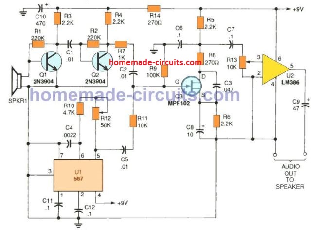
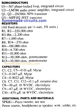
The last ultrasonic receiver circuit design is actually an extremely sensitive ultrasonic receiver which can easily pick up almost anything within the ultrasonic frequency range. You possibly can listen to insects, bats communications, engines, etc.; the idea could also be used in conjunction with the above explained ultrasonic generators for developing high quality ultrasonic systems.
The design, works using the principle of direct conversion. Transistors Q1 and Q2 boost the ultrasonic signals detected by the piezo speaker. The Q2's collector output is then used to drive the JFET (Q3) input, which can be seen hooked up like a product-detector circuit.
The PLL (U1) stage in this concept is employed like a tunable heterodyne oscillator which additionally feeds the input of the JFET detector circuit. The inbound ultrasonic signal combines with the frequency of the heterodyne-oscillator generating a sum and difference frequency.
The high frequency element is filtered out through the C3, R8, and C6 component network. The leftover low frequency output is allowed to enter across the LM386 audio amplifier input. A speaker or headphones could be attached to the circuit's audio output.
6) Another Ultrasonic Receiver Circuit for listening to Sounds above 20 kHz range
Also Recommended for you: How to listen to ultrasonic sounds
The frequency detection range of the our ear is hardly up to 13 kHz frequency. The function of the ultrasound detector is to defeat this limitation by switching the frequency of high frequency noises for example dog whistles, barely audible gas leaks, bat bleeping, and several artificial ultrasonic sounds for example lightly tapping on a newspaper.
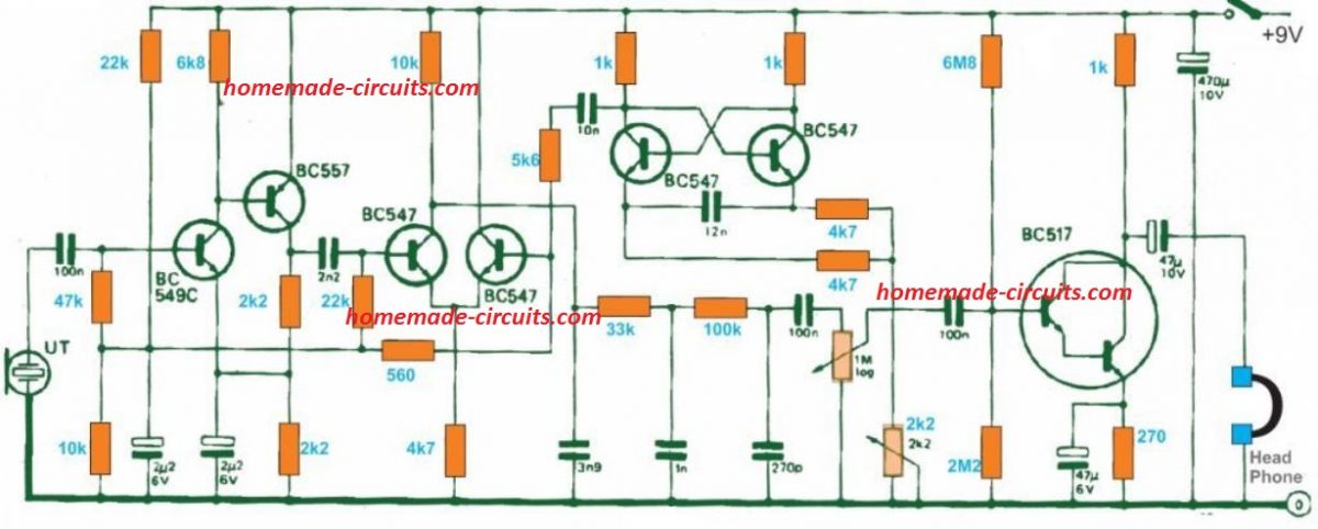
The 'ultrasound' detected by the input transducer is boosted and fed to a product detector. An astable multivibrator is included since the BFO stability may be not be of much significance. In addition for the required signal differential, the circuit additionally generates the BFO signal on its own as well as the summing frequency, which is then terminated inside a low pass filter fixed at 4 kHz.
The signal resulting here is yet again amplified to operate a set of headphones. The circuit works with around 8 milliamps, therefore it can easily be powered from a 9 V dry battery.


Comments
Swagatam! Thank you very much for sharing these designs – I’ve not been able to find off-the-shelf generators to the specs you have designed in #3 which is exactly what I’m looking for.
I am about to build several of these for a heterodyning experiment using ultrasonics, so before I start I wondered if you could advise how I might synchronize multiple generators? I’m assuming this would require another input/output circuit to do this – alas I do not have the knowledge as yet to do so.
If you could spare the time to either show how to do this – or put me on the right track, I’d really appreciate it.
Many thanks in advance!
Ian.
Thank you Ian, Glad you liked the post.
I checked the datasheet of the the IC LM567 and tried to find how multiple LM567 ICs can be synchronized with each other, however, unfortunately I could not find any relevant information. It seems this IC has no pinout support which can be configured with other identical circuits for the required synchronization. An external circuit cannot be used since the IC itself has no facility to accept and external synchronizing frequency.
If you have any further ideas or hints, please let me know, i will try to figure it out.
Thanks for your speedy reply – much appreciated.
Thanks also for checking the datasheet – I now understand this will not work for what I had in mind.
I do have 3x FY6900 signal generators I have synced up, so now I’m thinking to build 3 acoustic amplifier circuits, one for each of the 3 dual channel sig gens, and feed them into that speaker you built into #3 design. That way I would try to use the whole frequency range of 1 Hz to 500 KHz of the speaker (if that’s sensible/possible…!)
If you would be able to suggest a amplifier circuit (or an off-the-shelf amp) that would be suitable for this I would really appreciate it.
Would you also have a link to the speaker you suggested for the #3 design?
Many thanks Swagatam!
Thank you Ian,
What should be the specifications of the acoustic amplifier?
The speaker shown in the #3 PLL transmitter can be any small “Piezo tweeter”.
…also I’m trying to keep the circuit to a 12VDC supply, rather than 120/240v mains supply
Hey Swagatam – I’ve been on Chat GPT4 trying to figure this out as well, but I’m not clear enough in myself to ask the right questions to get the right answers…
I’m trying to produce a wide range of audio frequencies that I can adjust and combine, from infrasonic to ultrasonic, to see how they affect an impulsed resonant magnetic field in an encased toroid solenoid. Ideally I’d like to move the magnetic field via the longitudinal acoustic pressure waves. That’s the aim – I’ve got it all set up but the ultrasound unit I bought produces a 1.24 sec frequency sweep over 9 kHz which is no use for the experiment. I’m now looking to try to convert the combined signal generators output from, say, <1Hz to ~200kHz – into an acoustic sonic range with the ability to combine specific frequencies of interest. I found a couple of useful videos on youtube but I'm still a little unsure how they may or not be useful for this experiment.
Everything I do is entirely open source, of course.
Any advice on how to design a suitable amplifier and likely PSU for the job would be great!
Cheers,
Ian.
I appreciate your thorough explanation, Ian. Honestly, my understanding of audio and video is limited, and the topics you’ve covered may be outside my area of expertise. So I am not sure how to figure it out.
I really hope someone else on this forum is able to provide some help.
Or maybe if you could simplify the spec to make things easier to delve.
Thanks for your sharing
Can you share the basic ideas of design of 4) Ultrasonic Receiver Circuits please? Especially the part around the SPKR. That helps a lot!
Thanks
Thank you. The BC547 is a transistor which amplifies the tiny signals produced by the speaker in response to the ultrasonic waves applied by the transmitter circuit. If the frequency of the amplified signal matches with the set internal frequency of the receiver IC Lm567 then pin#8 activates and illuminates the LED
Thanks.
I’m now trying to build this receiver circuit centred at around 40kHz to detect and decode the ultrasonic signals with matching frequency. I built the circuit as instructed by your sharing but it turned out nothing happend. Do you have some advice?
Thanks
Did you confirm the exact frequency generated by the transmitter circuit? You will need a frequency meter for this. The transmitter output frequency will need to match with the frequency available across the C3 capacitor of the receiver circuit.
Thanks for your sharing
Would the results be affected by the types of the capacitors, ceramic, electrolytic etc?
Thanks
Yes, it can affect if you use the wrong type of capacitor in the wrong place.
Can we use same concepts to generate resonance frequency of 22.345GHz and how?
The battery in all these schematics is represented by single line (positive), where the other wire (Negative) would be connected? To the ground?
22.345GHz looks too high, Not feasible using the above circuits. Yes the negative of the battery goes to the ground line.
How do I download your circuits and related text? I do not desire Winzip or Shark although I already download Shark and started it.
Sorry, at the moment there’s no downloadable facility available in this blog.
Good Day, Swagatam: I hope it finds you and yours well. Thank you for sharing these circuits. I’ve just started classes, and look forward to building circuit recipes. I will try to build these- wish me good baking!
Thank you Cheryl, you can definitely try these circuits. All the best to you. Hope you succeed with the projects.
Hello,
The new features you have added are very good:
1. auto population of name and email id, when ‘Reply’ option is used.
2. mailing a copy of the posted comment.
suggesting one more addition to the above:
please mail (1st) a copy of the comment when posted.
currently I guess only when the comment is approved, user gets a copy.
next mail after the comment is approved/rejected.
Yes, it indeed looks good, it is a new commenting feature that I have installed in this website.
Swagatam,
a neighbor’s pet dog is creating nuisance, it barks endlessly mainly on 2 occasions:
1. when it wants attention.
2. when some dog or people walk on the street across the house gate.
To solve this public nuisance, it has to be trained to behave properly and the compound wall grills and gates are closed to block street.
We requested the owner to take remedial steps, but he is raking up unrelated and stupid issues. Then we gave a written complaint to municipal public health, animal husbandry, and police, but …
I find that ultrasound can deter dogs, found these among many others
1. amazon.in/Repeller-Ultrasonic-Training-Repellents-Anti-Barking/dp/B09DX8YY78/ref=asc_df_B09DX8YY78/?tag=googleshopmob-21&linkCode=df0&hvadid=586293095165&hvpos=&hvnetw=g&hvrand=2004944213184527759&hvpone=&hvptwo=&hvqmt=&hvdev=m&hvdvcmdl=&hvlocint=&hvlocphy=9062011&hvtargid=pla-1658249252631&psc=1
Review says don’t buy.
2. amazon.in/gp/product/B07NKD4LW8/ref=ox_sc_act_title_1?smid=A1BE4CFIAAE12Y&th=1
mixed fb.
Effective range and power of the above 2 devices are not clearly mentioned.
Dog is about 20-30 mts away from our bld.,
Can your ckt 3 be effective as a Dog repeller device?
Hello Sesha,
Those gadgets definitely work, but I am not sure about the range.
https://en.wikipedia.org/wiki/Dog_whistle
I think the range of the above circuits can cover a distance of 30 meters.
The first circuit can also be tried. You can create more amplification from the speaker by including a transistor driver stage at pin#3 of the 555 IC.
I also have a dedicated article on this subject which you can read below:
https://www.homemade-circuits.com/simple-electronic-dog-whistle-circuit-explained/
hello, swagatam.
thanks for the inputs. i cheked your dog-whistle circuit also, simple, but i won’t be able to assemble any ckt due to eyesight and shakey hands. gone are the days when in college i assembled power-amp using tba810 – designed and fabricated the enclosure using aluminium sheet in college workshop, got the transformer wound in local shop and bought the components from Lajpat Rai market, Delhi, and soldered/assembled them. I still have that dabba somewhere in the attic – nostalgic.
my requirements and final design plan:
1. an input noise sensor (any noise or if possible tune it to dog barking, like the anti-theft car alarm sensor)
2. your simple circuit 2 (or complicated ckt 3) with 50% duty cycle.
3. auto-off after a delay ( say 1-2 min)
4. preferably auto change the freq after every off-on (like the serial lights changing the on/off pattern)
5. output power-amp ( i checked tba810, its freq range is 20hz to 20khz).
i feel combining 4 or 5 ready-made/off-the-shelf ckts should meet requirements.
There are many ready-made cheap ( about rs 500) “ultrasonic pest repellent” boxes in amazon.in, but not sure about the specs (power, freq and effective range) and if it will be effective against dog.
if yes, point 2 is taken care of, and I need to find suitable ready-made ckts for other points.
looking forward to your inputs.
I am adding:
6. a LED indication when the tweeter (load) is ON – like LED1 in ckt 4.
say adding a led in series to an existing resistor or adding a new resistor+led on the output side
You can add an LED parallel to the tweeter wires….it will illuminate when the tweeter is ON.
Thanks, i guess a resistor is also needed in series to control current.
please specify R value and LED1 (in ckt 4 also) spec/no
Circuit#4 is a receiver, not a transmitter. Where do you want connect the resistor and the LED?
in the transmitter, similar to LED1 in the receiver
In Circuit#3 transmitter circuit, the LED can be connected between pin#5 and ground with a 1K series resistor.
in ckt 2?
Connect the LED parallel to the speaker wires with a 100 ohm resistor
Hello Swagatam,
I thought I replied to you, but unable to find my final reply. is it pending for approval?
Also I find the site has been updated.
Let me try to recollect:
my requirements can be met my combining the following modules:
1. an input “noise/sound sensor/detector”, say one from robu
2. on/off delay timer – your “Delay from an External Trigger”
or any off-the-shelf boards.
electronicscomp.com/6-30v-1-channel-power-relay-module-with-adjustable-timing-cycle?gclid=CjwKCAiAleOeBhBdEiwAfgmXf7qB5PCEh-qOKKBrGS4aN1F4Zrcyh_grVXiT1piYpO7Rn4Ijk9rCkxoCnrIQAvD_BwE
in P4 mode, will it meet my requirements?
3. Ultrasonic sound generator – your simple ckt 2 with LED parallel to the speaker wires with a 100 ohm resistor.
4. Power amp: Your Power Amplifier Circuit using IC 741 and MOSFET (can it work in Ultrasound freq say 20khz-40khz?)
5. 12V dc supply with reqd A (say one that is used with wifi-router)
Can you supply modules 2,3 and 5 and suggest modules 1 & 5.
And how to interconnect these modules.
I can put them together in a plastic box or in a scrapped AM/FM radio box.
Looking forward to your reply.
Hello Sesha,
How do you want the ON/OFF delay timer to work with the ultrasonic generator? I don’t seem to remember it.
ON when sound is detected, OFF after a delay say 30 sec-1 min (perhaps tunable)
and remains OFF for some time say 30 sec-1 min (to avoid infinite loop)
if the sound continues or a new sound is detected, goes ON.
something like car anti-theft alarm, alarm is put OFF after a delay, instead of manually.
I don’t understand the different ‘modes’ of the above ckt, but guess one of the modes can meet my requirement.
for the power supply, a 220V ac to 12V dc 2A off-the-shelf module board from amazon/robu … should be good enough?
That delay timer with both ON/OFF can be difficult to design for me. I have a circuit which will be stay ON for sometime (adjustable) when it detects sound…. but as soon as it is OFF, it can be triggered with subsequent sound inputs.
Lets say it detected the sound and goes ON. I set the OFF time to say 2 mins.
Then there are two scenarios:
1. The sound goes OFF (say in 1 min) before the OFF time (2 min), in this case, the ckt goes OFF in 2 min.
2. The sound continues for say 3 min, when will the ckt go off?
after 3+2 = 5 min? ie basically keeps getting retriggered?
If yes, then its ok.
The circuit cannot be re-triggered while it is ON and counting. It can be re-triggered only once it is OFF, after the delay is completed. So it will be 2 minutes alarm ON, after this 2 minutes is complete only then the circuit can be initiated for the next cycle by the input sound.
Let’s say Tton is the timer ON time (or delay time)
What are the min and max values for Tton that can be set?
After Tton elapses, is there a min time that is required before it can be retriggered?
Let’s say the external trigger/sound continues beyond Tton will the circuit start all over again and continue till Tton is reached?
OR it will not start at all?
Let’s say Tton is set to 2 min, external trigger/sound continues (could be non-stop, or in busts) for 5 mins and then completely stops. Will the ckt go OFF after 6 mins OR after 2 mins?
I want the ckt to be ON for some more time (Tton ) than the external sound is audible.
I have figured out a circuit which can produce both ON time and OFF delays for the output relay. Here’s the design.
https://www.homemade-circuits.com/wp-content/uploads/2023/02/ultrasonic-delay-circuit.jpg
Thanks. Since there is no explanation of the ckt, I don’t know how/where to set the ON & OFF timings.
And I am confused.
I think your Delay from an External Trigger ckt should work, the Input Trigger being the output of a Sound detection module. And the output goes to Ultra sound generator.
Given my following requirements, please suggest appropriate modules that you can supply/vendors to buy from:
1. an input “sound sensor/detector” to detect Dog barking sound.
2. OFF delay timer to keep the tweeter speaker ON for ‘sometime extra’ after the dog stops barking.
3. Ultrasonic sound generator that can repel dogs, with a 15 mtr effective range.
4. Power amp for extra range (upto 15 mtrs) and power
5. 220V ac to 12V dc module with reqd power rating (Amps) to power all the above modules.
Thanks
According to my understanding, dog barking sound will hit the MIC, which will be amplified by transistors T1, T2, T3, and supplied to T4. T4 will trigger ON the IC 555 delay OFF timer, which will immediately switch ON its relay for some time. The relay will switch ON the ultrasonic generator.
After the time has elapsed, the IC 555 will switch OFF the relay and the ultrasonic generator.
R10, C4 can be adjusted to adjust this ON delay period.
Whereas C3 and 100K can be adjusted to adjust the time period for which the IC 555 and the relay remains disabled or paused.
I have designed the circuit that you were looking for. The remaining modules can be purchased as per your requirement.
Thanks a ton for designing a ckt specifically for me.
This takes care of points 1 and 2 of my requirements.
Instead of the relay, the output can be connected to your ckt 2 Ultrasonic Generator with Fixed 50% Duty Cycle, along with LED parallel to tweeter with a 100 ohm resistor.
Please suggest a suitable power amp from your collection and an off-the-shelf PS module.
Can you supply modules 1 to 4?
Cost + shipping to Bangalore if any?
Yes, the relay can be removed and the pin#3 of the 555 can be used to power the ultrasonic generator.
For the amplifier you can simply attach a TIP122 with the generator circuit in the following manner:
https://www.homemade-circuits.com/wp-content/uploads/2023/02/ultrasonic-genertaor-with-amplifier.jpg
Sorry, it won’t be possible for me to supply assembled modules, due to work load.
1. hmm. if not assembled board, can you supply all the PCBs, I buy components and get them soldered by someone.
2. where to connect ic555’s pin#3 output to the ultrasonic generator? ie what is the input pin of ug?
I wish I could help but due to work pressure it will not be possible for me to design the PCB either.
You can connect the pin#3 and ground of the IC 555 with the supply +/- pins of the 4049 IC.
Before building this project I would like to advise you that this project is not easy and will require a through knowledge electronic circuits and concepts, so that if you happen to get stuck with a problem you can troubleshoot it quickly with your prior knowledge and understanding.
Thanks. I can try only if all the pcbs are available.
OK, no problem.
Hello Sesha,
I am sorry to hear about your physical ailments.
In your requirement, point 2 and 5 can perhaps be purchased ready-made. It is easier to buy ready-made units from amazon.
points 1 and 4 are not within my range so I cannot design them.
I can design only point 3.
Let me know your thoughts on this.
Thanks.
Point 4 is not a must.
point 1 “noise sensor” gives few off-the-shelf boards.
point 2 please suggest.
how about one of the “ultrasonic pest repellent” boxes in amazon.in? Hopefully, it has space and dc voltage/power to meet other ckts.
Or buy an ultrasonic board and an appropriate AC/DC power module that meets all the boards requirements and also fabricate a box.
point 3 please suggest. “automatic on/off timer switch” gives few off-the-shelf boards.
in P4 mode will meet my requirement?
point 5 please suggest, along with a tweeter speaker.
look forward to your inputs.
Circuit#2 already has 50% duty cycle.
Yes you can go for the ready made units as preferred by you. No issues.
For the timer you can refer to the second schematic from this article:
https://www.homemade-circuits.com/simple-delay-timer-circuits-explained/
For the amplifier, you can try this:
https://www.homemade-circuits.com/power-amplifier-circuit-using-ic-741-and-mosfet/
This is a topic that is near to my heart… Best wishes! Where are your contact details though?
Hello,
What speaker do i have to use when building the circuit? Would a MUS-40S be possible in a transmitter circuit?
Thank you for these awesome designs!
Glad you liked the post.
You will have to use a piezo based speaker such as this one:
https://www.homemade-circuits.com/wp-content/uploads/2020/02/piezo-transducer.jpg
A tweeter will also work which are used in amplifiers.
hi, i’m looking for ultrasonic circuit used for laundry
Sorry, I do not have that circuit at this moment o time.
I’ve built the PLL Ultrasonic Generator and have gone through the circuit multiple times to make sure it was as shown on the diagram. Ive blown the 470uF capacitor twice. Im using the 16V capacitor with my 12V power source. Ive even tor down the circuit and rebuilt it with the same result.
Your 16V capacitor will blow if the supply voltage exceeds 16V. If your supply voltage is exceeding 16V then you must use a capacitor rated at 25V or 35V.
By the way the circuit diagram recommended 9V as the supply input, therefore you must use a 9V DC for the circuit.
I want to send microphone audio to a receiver with headphones at 35-45khz. My idea is to water proof my circuit and let the transducers use water at the lake as the transmission media. Possibly modulate a 45khz oscillator. What do you think?
It may be possible, however it will first need confirmed on a small-scale.
I dont quite understand what you are saying about confirmed on a small scale.
I built a Very very low freq receiver about 20 years ago to listen to things below 50khz.
It was fun but now I think that I could modulate a 40khz or so freq with modulation, and by having the transducers underwater i could use the water to carry the sound from my scuba mask to a module built on a small bouy that would take that recovered audio and connect it to a on board small 200mw 146.00Mhz two-way radio module setup on a cross band (VHF to UHF) radio in my vehicle parked at the lake, to repeat my signal to our local ham radio repeater located on a mountain top a few miles away. Kind of like Maritime Underwater mobile.
I am very familiar with the NiceRF SA818 walkie Talkie module that would be used for this project.
I think i just need some direction on ideas and will be able to build the needed circuits.
I’m not looking to produce more than one or two of these for myself and a fellow ham radio operator/Scuba buddy.
We ham radio operators can come up with some pretty wild projects, building them and then giving talks to other clubs about our achievements is part of the fun also.
What do you think of my idea?
Thanks for your time on this.
Earl
I mean to say I am not sure whether the ultrasonic waves will be able to traverse through water or not, therefore this needs to be confirmed on a small water tub.
For modulation you can probably use the first IC 555 based transmitter circuit. For modulation, an amplified voice frequency could be applied on the pin#5 of the IC.
Can I use a 2N2222 transistor instead of a BC547 on the transmitter and receiver?
Would I need to change any resistor or capacitor values for bias conditions if that is the case?
yes you can do it without any changes in the circuit
Hello, I would like to make a small ultrasonic receiver over 40KHz. reliable able to operate a small low voltage relay ON OFF 5V .. 3.3V.
The transmitter should be pocket sized, similar to radio frequency ones. TX and RX should have the ability to send coded ultrasound (coder-encoder) is it possible to pass the generated signal through an MM53200 or similar?
Thanks in advance
Hello, I checked the datasheet of the IC and it seems that may be possible….
http://www.farnell.com/datasheets/105708.pdf
Have you a circuit that would allow the output to be varied from 0-100%?
Your site is great! Really appreciate your efforts at sharing
Thanks
Doug
How about a circuit that senses the inaudible pitch on tv commercials to mute my tv?
Hi Maurice, yes it may be effective depending on the power output. Frequency can be anywhere from 15kHz to 25kHz