In this post I have explained a very simple 3-phase sine wave generator circuit, using only three bipolar transistors and a few passive components for initiating the desired three phase output.
How it Works
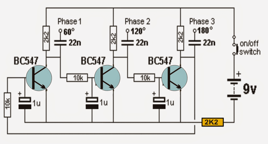
Referring to the 3 phase sine wave generator circuit we can see three identical transistor stages configured in a cross coupled manner, having equivalent RC timing constants across their bases.
The 10k resistor and the 1u capacitor essentially become responsible of providing the required delay effect for generating the intended 3 phase signals with 120 degree phase shift.
When power is switched ON, the stages may seem to undergo a locked sequence, however since all the capacitors cannot have a precisely same value, the one which has a shade lower value than the other charges up first, triggering a sequential conduction across the transistor.
Let's assume that due to inconsistency in values, the middle transistor base capacitor gets charged first, this enables the middle transistor to conduct first which in turn grounds the base of the extreme right transistor preventing it from conducting for that instantaneous moment, but in the meantime the base capacitor of the left or the right transistor also gets charged in tandem which forces the middle transistor to switch OFF and release the right transistor conduction.
Push Pull Cycle
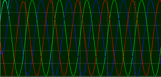
The above mutual push and pull procedure induces and settles into a continuous sequential train of conduction across the transistors causing the intended three phase signal pattern to appear across the collectors of the transistors. Owing to the gradual charge and discharge pattern of the caapcitrs, the resultant signal shape is a pure sine wave.
The 2K2 resistor shown in yellow strangely becomes crucial in initiating the 3 phase signal generation sequence, without which the circuit seems to stall abruptly.
As mentioned before the degree of phase may be altered by changing the RC values across the bases of the transistors, here it's configured to produce a 120 degree phase shift.
Circuit Diagram
Oscilloscope trace, 3 phase waveform
Video Illustration
Since my scope was not equipped to measure 3 phase signal, I could only manage to check a single channel in the video.

Questions & Answers
sir, this circuit normally or can be used for anything?
thank you /
only for 3 phase related applications.
Can I run hard disk motor with this?
I am not sure, you can try though
hai mr. swagatam,
can i use this circuit to make it as input for the 3 phase H-bridge Mosfet circuit to drive the BLDC rotor from honda motorcycle safely? or i need another complicated circuit again? thanks..
dhyaks@gmail.com
Hi Dhyaksa, I think it'll work, at least there's no harm in trying it out….since it's designed to produce a 3 phase output with a 120 degree phase shift, it should work as expected.
okay i will try it.. because of my old built in ECU for triggering the BLDC was died, and to buy a new one is quite expensive, i try to make it one, is there any potential problem to use this circuit for drive a High and Low mosfet together in each Phase of final Mosfet 3 Phase circuit then? what do you think? before i start to make it.
if you are using a driver IC for driving the mosfet bridge then the above circuit can be tried without much fear, because the driver IC will be smart enough to detect any issue and prevent the mosfets from blowing of.
Hello! I was wondering if I can simply use a 12v supply instead of the 9v in schematic, at the present components ratings? If not and components need to be swapped out for different rated ones, what would they be or where do I find the information to know? Thank you, Tim
yes 12V can be used but it might cause a slightly different frequency at the output, you can adjust it by tweaking the values of the resistances or the capacitors or both.
regarding components you an read the following comprehensive article:
https://www.homemade-circuits.com/2015/09/how-to-identify-component-specs-in.html
Thank you very much for the quick response and information Swagatam Majumdar!
Does this circuit has any formula for frequency. Because I'm going to make a bldc driver. And can the frequency be varied.
BLDC circuts work by sensing back emf or signals from the hall-effect sensors….you won't need a 3 phase generator circuit for it.
How would you get the high low needed six ouputs for the half bridge?
connect NOT gates with each of the transistor collectors…the o/p from the gates could then be used for the half bridge
Can this circuit be used to drive three leds
yes.
Great work as always. I refer a lot on this site. Great source for hobbyist like me. good work. BTW, is this 3 phase output shown is with or without load? will it be disturbed on some minimal load?
I'm glad you liked my site….yes the shown output is without load and will get disturbed with any kind of load…a buffer stage will be required for accessing the 3 phase output correctly
Sir can it be applied to three phase inverter circuit to produce three phase sine wave?
Does the moasfet drivers give sine wave output if we use this as input?
Athri, no that won't happen, because the mosfet driver will convert it into square waves, and the output will be also a square wave only.
Hello sir, do you think we make differential 3 phase shifter with this architecture?
Hello Bhanu, can you please specify why do you think that this circuit could be relevant to a differential 3 phase shifter?
Hello Sir,
I want to take a strong signal for some experiments.(To reinforce the signal)
What can I do? Do you have a schematic in order to I can multiply the multi watt phases (as more are better).
best Regards
P.I e-mail sunrisezero@yahoo.gr
Hello sunrisezero you can try connecting TIP122 BJTs with the output leads of the circuit, and get strong outputs from the collector or the emitter of the BJTs
It is very easy actually, just connect the bases of the respective TIP122 BJTs with the phase1,2,3 outputs, connect their collectors with the positive supply, and finally strong signals can be obtained from their respective emitters.
The plan suggested by me is right, and you must try exactly the same plan.
the collector/emitter voltage of TIP122C is 100V, in the emitter follower mode as suggested by me, the base pattern and voltage will be replicated at its emitter, so if the above BC547 3 phase circuit is operated with 12V, the emitters of the TIP122 would also replicate the same sequence at a little less than 12V
Dear Swagatam,
Thank you very much.I'll try it.
Best Ragards
P.I
sir can I use this circuit to drive my 3phase inverter transformer for 3phase ac output
kels, yes you can do it, I have posted quite a few dedicated articles related to this topic which you can search in the website and refer them…
Dear Swagatam,
I would like to have your opinion on my choice as to the power of section in ultrasonic area.
I attach a video (YT) that shows some patterns of sections.
Please let me know the most powerful for ultrasounds (I want to use it for dog repeller in distance).
In the video I have 5 section.
What would you suggest to me for each one.
I’ll use piezoelectric transducer.
best regards
P.I
Dear sunrise, the design which uses 4 transistor bridge-network will produce the most powerful output.
Dear Swagatam,
Thank you.
How much power according to the plan could be at 12 volts?
P.I
the power may be almost equal to the 12V x load current specification.
ok thank you
hi
how can count the frequency of this oscilator
By using a high impedance frequency meter and connecting it across the transistor collector emitter
Good evening, I would like to build a power supply with three-phase output 400 hz power 100/200 watt 115volt.
I saw its circuit with inp sinus and output from lm324, three-phase. could I have the scheme of the unit ‘power? Is it possible to use 3 transformers? Unfortunately I can’t find a three-phase core for these small powers. I hope to be understood.
Thank you and best regards
Julian
Hello Guilliano, I guess you are referring to the 3 phase inveter circuit, using LM324 3 phase generator. Te power of the output can be any magnitude depending on the power of the MOSFETs used, and also the input supply ratings..
Transformer can be used if it is designed correctly as per 3 phase configuration.
Hello, thank you for your response. Excellent circuit
I’d like to know if the output frequency on the three phases, it’s 400 cycles.
Best regards
Giuliano
Thanks, glad you liked the post! The frequency can be adjusted to any desired level by tweaking the values of the base resistor and the capacitor, both together or either the capacitor or the resistor individually.
Thank you, now I’m going to proceed to the experimentation
Greetings
Wish you all the best!
Dear Friend,
I don’t understand the last sentence of the description, about the phase shift degree values. I’d expect the R-C values determine the frequency, and the phase degrees, supposed all three transistor blocks are the same, remain always 0, 120 and 240 degrees.
Am I wrong?
The transistors are conducting sequentially and producing signals with 120 degrees separation across each other
Dear Mr. Swagatam,
Interested in having a 60-watt 3-phase sine wave power device to drive a three-phase trafo from the 60-Hz mains. I would like to have a circuit from your side for discussions, to be finalized with the placement of purchase order for the hardware of the bench version, a functioning circuit board will do. RSVP.
Sincerely,
MingChing Teng
Apr. 19 ’20 ( Sun. )
Thank You Ingching, You can find all the required details under this page, however I don’t sell these items.
https://www.homemade-circuits.com/?s=3+phase
The derivation to earth of the excess energy in permanent generators where the field cannot be reduced has always called my attention, the question is: why not make a three-phase rectifier with three diodes, its anode to earth and three scr its cathode to the positive of battery, controlling the conduction of these scr the necessary current is sent to the battery and there is no need to dissipate the extra power with temperature on the stator and on the device that performs the function of switch, either transistor or scr, in addition there would be no consumption engine power or fuel…
the difficulty with the triple oscilloscope display . Like everything else – tools for the job . Designed , constructed 8 channel display for single beam oscilloscope – more than 20 years ago . Been looking around for a ‘partner’ to commercially “”””exploit”””” that product .
Did make a version of the bc547 – triple sine – building better / neater version .
Also constructing digital version = with a few wrinkles to that
I now live in Cypus – which is difficult re forming tech cannot get the bits , licences and taxes . In uk ???????
As regards that 2k2 resistor in yellow suspect that with it not fully discharged the transistor – thus that little bit just enough to permit oscillation
Sir, if i add three transistors bc 547, so that six, Will it be 360 sin?