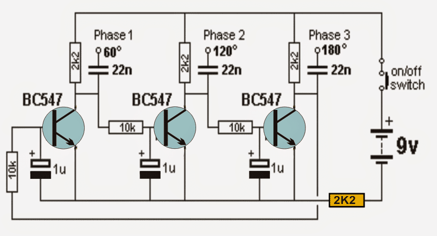
In this post I have explained a very simple 3-phase sine wave generator circuit, using only three bipolar transistors and a few passive components for initiating the desired three phase output.
How it Works
Referring to the 3 phase sine wave generator circuit we can see three identical transistor stages configured in a cross coupled manner, having equivalent RC timing constants across their bases.
The 10k resistor and the 1u capacitor essentially become responsible of providing the required delay effect for generating the intended 3 phase signals with 120 degree phase shift.
When power is switched ON, the stages may seem to undergo a locked sequence, however since all the capacitors cannot have a precisely same value, the one which has a shade lower value than the other charges up first, triggering a sequential conduction across the transistor.
Let's assume that due to inconsistency in values, the middle transistor base capacitor gets charged first, this enables the middle transistor to conduct first which in turn grounds the base of the extreme right transistor preventing it from conducting for that instantaneous moment, but in the meantime the base capacitor of the left or the right transistor also gets charged in tandem which forces the middle transistor to switch OFF and release the right transistor conduction.
Push Pull Cycle
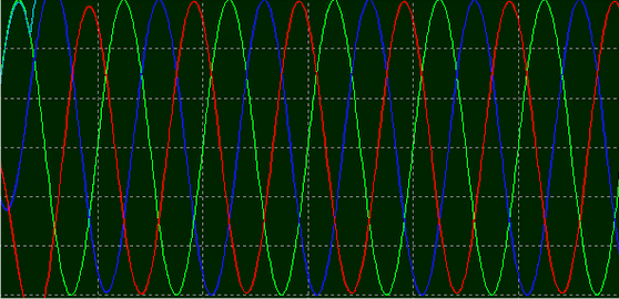
The above mutual push and pull procedure induces and settles into a continuous sequential train of conduction across the transistors causing the intended three phase signal pattern to appear across the collectors of the transistors. Owing to the gradual charge and discharge pattern of the caapcitrs, the resultant signal shape is a pure sine wave.
The 2K2 resistor shown in yellow strangely becomes crucial in initiating the 3 phase signal generation sequence, without which the circuit seems to stall abruptly.
As mentioned before the degree of phase may be altered by changing the RC values across the bases of the transistors, here it's configured to produce a 120 degree phase shift.
Circuit Diagram
Oscilloscope trace, 3 phase waveform
Video Illustration
Since my scope was not equipped to measure 3 phase signal, I could only manage to check a single channel in the video.

Questions & Answers
I constructed the circuit, and i also purchased a 4 channel scope to view the results. ’twas awesome! after changing out the caps and resistors for slightly different values i was able to achieve a very smooth, nearly perfect sine wave. (the vertical symmetry was nearly perfect, the top positive peak of the wave was slightly more rounded than the bottom negative peak, the lateral symmetry was perfect)
I changed out the 2k2 resistor on the negative feed for a 10k trimpot and was able to tweak the frequency to 60 Hz. (at fist the frequency was around 480 Hz.) .
Mostly, i do understand your explanation for the circuit, however, I am puzzled as to how it produces the negative portion of the wave…
Are you able to design a 3 phase circuit similar to the one above that can drive a tiny 3 wire DC permanent-magnet-rotor motor?
Thank you so much for your useful feedback and for perfecting the component values.
It is actually not the negative portion of the waveform, it is the section between the positive voltage peak and the 0V level, it happens when the capacitors gradually discharge until 0V is reached, and then climbs back to the positive peak…
Designing 3 phase circuit can be difficult because it will require creating a phase difference of 120 degrees, which cannot be done using basic analog circuits.
this circuit does work, I built and tested it,
but there’s no way in heck those oscilloscope graphs are from this circuit,
I get triangle waves, not sine waves, and there’s a 50-percent off time
between the triangles, so don’t expect this to be useful as is 🙁 !!!
You can see the video proof which shows how well the circuit works, please change your oscilloscope and check again..
This thing is so simple and elegant that it blows my mind. never thought of doing it by simply using the phase shift off a capacitor.
Till now i’d been doing this using an Arduino and 3 H-bridges, now i think i can use this circuit to drive some IRF830’s or some-such. so much simpler…
Sir,What is the maximum frequency of this circuit.
Thanks in advance.
The frequency can be perhaps increased upto many MHz.
How can i make it maximum to 50hz without interfering with the circuit specifications or can i attach
the pwm output signals from tl494 circuit Having a set freq of 50hz to the input of this circuit to make it 3 phase 50hz output signal?
The above circuit generates its own frequency, it cannot be connected with an external PWM frequency. The 10uF, and 10K values can be changed to change the 3 phase frequency.
Sir which formular do i apply to make the generated frequency to be 50hz
Joseph, sorry, I do not have a formula to calculate the frequency, you will have to do with some trial and error process.
Very cool, this will help me out. I would like to use this as a gate driver for a brush-less 3 phase motor controller; can I increase the frequency by lowering the 10k resistor value?
Thanks, and hope the circuit works for your application. Yes, the 10K can be adjusted to change the output frequency.
Is there a formula for the RC time constant if you change the voltage? I’m looking to use 24V and still maintain 120 degree phase shift.
yes there is a formula for RC time constant, you can find it here:
https://en.wikipedia.org/wiki/RC_time_constant
I believe i got the circuit right, all my voltages at the E, B and C are the same measuring to common ground. Across the phases I’m getting 5.4mV, -0.4mV and -5.4mV. Does this behave differently than a high voltage AC 3 phase. Unfortunately I don’t have a scope but I’m not to concerned with the duty cycle right now only that it’s 3 phase.
Whenever a waveform is involved, an oscilloscope is a must for verifying it. Without checking the waveform it can be almost impossible to know whether the circuit is working correctly or not.
Thanks for your quick replies it is really helpful when you get stuck.
After a lot of thought I am beginning to think it is theoretically impossible to simulate AC 3 phase with DC voltage because of the commons, DC will always need a (-) to go to, but AC waves are identical except for the phase shift. I wish I had a scope to verify for sure. But it is more the behavior I’m looking for, because our apprentices aren’t allowed to touch high voltage. I measure 7v at the phase outputs (from common) and removing a leg there is still 7v on the other 2, but no reading across the dead leg and a live one.
The three transistors will never conduct simultaneously, they will only conduct sequentially and exponentially. I have tested the circuit using an oscilloscope and could get a sine wave output across each of the outputs, so I believe the circuit should work as expected.
But with the DC component will it behave as AC Delta?
This will again need to be confirmed by connecting the 3 outputs of the circuit to an oscilloscope which can measure 3 phase signal. Actually the signal has been already tested by someone else, and the image is given in the second figure from top.
Thanks for all the help. I wish I had a scope. I believe the circuit works because of the voltage readings I’m getting, I will recheck my breadboard wiring.
No problem, wish you all the best!
dear Sir, i would like to know if this circuit can be powered with 220AC 50hz (Italian power) maybe with rectifier diodes at the input instead of the 9v battery supply without any changes in the components used?
And with 12volt battery?
How many volts in generate on the 3phase output at 9v, 12v or 220v input?
Thanks a lot.
Hello Walter, yes this circuit can be powered from a 220V AC to 12 DC adapter
Sir, if i add three transistors bc 547, so that six, Will it be 360 sin?
Yes it seems that can be achieved.
the difficulty with the triple oscilloscope display . Like everything else – tools for the job . Designed , constructed 8 channel display for single beam oscilloscope – more than 20 years ago . Been looking around for a ‘partner’ to commercially “”””exploit”””” that product .
Did make a version of the bc547 – triple sine – building better / neater version .
Also constructing digital version = with a few wrinkles to that
I now live in Cypus – which is difficult re forming tech cannot get the bits , licences and taxes . In uk ???????
As regards that 2k2 resistor in yellow suspect that with it not fully discharged the transistor – thus that little bit just enough to permit oscillation
Dear Mr. Swagatam,
Interested in having a 60-watt 3-phase sine wave power device to drive a three-phase trafo from the 60-Hz mains. I would like to have a circuit from your side for discussions, to be finalized with the placement of purchase order for the hardware of the bench version, a functioning circuit board will do. RSVP.
Sincerely,
MingChing Teng
Apr. 19 ’20 ( Sun. )
The derivation to earth of the excess energy in permanent generators where the field cannot be reduced has always called my attention, the question is: why not make a three-phase rectifier with three diodes, its anode to earth and three scr its cathode to the positive of battery, controlling the conduction of these scr the necessary current is sent to the battery and there is no need to dissipate the extra power with temperature on the stator and on the device that performs the function of switch, either transistor or scr, in addition there would be no consumption engine power or fuel…
Thank You Ingching, You can find all the required details under this page, however I don’t sell these items.
https://www.homemade-circuits.com/?s=3+phase
Dear Friend,
I don’t understand the last sentence of the description, about the phase shift degree values. I’d expect the R-C values determine the frequency, and the phase degrees, supposed all three transistor blocks are the same, remain always 0, 120 and 240 degrees.
Am I wrong?
The transistors are conducting sequentially and producing signals with 120 degrees separation across each other
True, but the diagram still shows 60, 120 and 180 degrees…
may be the diagram is designed for 60 degrees, so it will need to verified and then the parts can be sightly modified for getting 120 degrees
Thank you, now I’m going to proceed to the experimentation
Greetings
Wish you all the best!
Hello, thank you for your response. Excellent circuit
I’d like to know if the output frequency on the three phases, it’s 400 cycles.
Best regards
Giuliano
Thanks, glad you liked the post! The frequency can be adjusted to any desired level by tweaking the values of the base resistor and the capacitor, both together or either the capacitor or the resistor individually.
Good evening, I would like to build a power supply with three-phase output 400 hz power 100/200 watt 115volt.
I saw its circuit with inp sinus and output from lm324, three-phase. could I have the scheme of the unit ‘power? Is it possible to use 3 transformers? Unfortunately I can’t find a three-phase core for these small powers. I hope to be understood.
Thank you and best regards
Julian
Hello Guilliano, I guess you are referring to the 3 phase inveter circuit, using LM324 3 phase generator. Te power of the output can be any magnitude depending on the power of the MOSFETs used, and also the input supply ratings..
Transformer can be used if it is designed correctly as per 3 phase configuration.
hi
how can count the frequency of this oscilator
By using a high impedance frequency meter and connecting it across the transistor collector emitter
Dear Swagatam,
I would like to have your opinion on my choice as to the power of section in ultrasonic area.
I attach a video (YT) that shows some patterns of sections.
Please let me know the most powerful for ultrasounds (I want to use it for dog repeller in distance).
In the video I have 5 section.
What would you suggest to me for each one.
I’ll use piezoelectric transducer.
best regards
P.I
Dear Swagatam,
Thank you.
How much power according to the plan could be at 12 volts?
P.I
ok thank you
the power may be almost equal to the 12V x load current specification.
Dear sunrise, the design which uses 4 transistor bridge-network will produce the most powerful output.
sir can I use this circuit to drive my 3phase inverter transformer for 3phase ac output
kels, yes you can do it, I have posted quite a few dedicated articles related to this topic which you can search in the website and refer them…