• Skip to main content
  • Skip to primary sidebar

Homemade Circuit Projects

Need circuit help? Post them in the comments! I've answered over 50,000!

Blog | Categories | About | Contact | Calculators-online
You are here: Home / Inverter Circuits / 1500 watt PWM Sinewave Inverter Circuit

1500 watt PWM Sinewave Inverter Circuit

Last Updated on January 19, 2025 by Swagatam 216 Comments

A vey basic yet reasonably efficient 1500W PWM based sinewwave inverter circuit can be studied under this post. The design utilizes very ordinary parts to accomplish a powerful SPWM type inverter circuit.

Table of Contents
  • Main Specifications
  • The Design
  • Circuit Operation
  • The Objective behind this Logic Configuration
  • The Oscillator Stage
  • About the Mosfets and the Transformer

Main Specifications

Power Output: Adjustable from 500 watts to 1500 watts

Output Voltage: 120V or 220V as per the transformer specs

Output Frequency: 50Hz or 60Hz as per requirement.

Operating Power: 24V to 48V

Current: Depending on the Mosfet and transformer Ratings

Output Waveform: SPWM (can be filtered to achieve a pure sinewave)

The Design

The proposed 1500 watt PWM sinewave inverter is designed using extremely basic concept through a couple of IC 4017 and a s single IC 555.

In this concept the sequencing logic from the output of the IC 4017 are configured by selecting and skipping subsequent pinouts such that the resultant sequencing produces a decent SPWM like switching on the connected mosfets and the transformer.

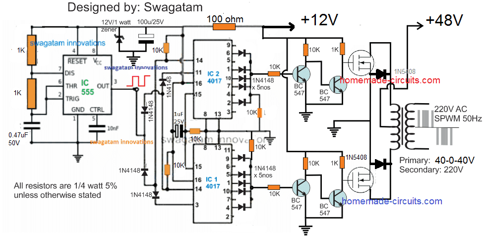
The complete schematic could be visualized in the following diagram:

SPWM sine wave 1500 watt inverter circuit diagram using IC 4017

The working of the Inverter can be understood from the following explanation:

Circuit Operation

As can be seen, two IC 4017 are cascaded to form an 18 pin sequencing logic circuit, wherein the each negative pulse or frequency from the IC 555 produces a shifting output sequence across each of the indicated outputs of the two 4017 ICs, starting from pin#9 of the upper IC upto pin#2 of the lower IC, when the sequence is reset to initiate the cycle afresh.

We can see that the output of the IC 4017 are intelligently tapped by skipping and combining sets of output pinouts such that the switching to the mosfets achieves the following kind of waveform:

SPWM image from IC 4017 inverter

Acording to the waveform, the start and the end sequences can be seen being skipped by eliminating the relevant pinouts of the IC, similarly, the second and the  6th pinouts are also skipped, while the second, 4rth, 5th, 6th pinouts are joined for accomplishing a decent SPWM like pulse form across the outputs of the two 4017 ICs.

Video Proof (100 watt example)

The Objective behind this Logic Configuration

The above shown waveform is selected so that it is able to replicate the actual sinusoidal or sine waveform as closely as may be possible.

Here we can see the initial blocks are eliminated so that the SPWM waveform can match the actual sinewave's initial lowest RMS value, the next two alternate blocks imitate the average rising RMS within a sinewave, while the center 3 blocks tries to replicate the maximum RMS of an  exponentially rising sinewave.

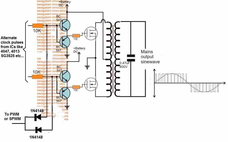
When the above PWM format is applied to the gates of the mosfets, the mosfets alternately execute the switching of the transformer primary with the very same switching format in a push pull manner.

This forces the secondary synchronously to follow the induction pattern with an identical waveform which ultimately results in the creation of the required AC 220V, having the above SPWM waveform pattern.

An appropriately dimensioned LC filter across the output winding of the transformer may finally allow the secondary side to achieve a perfectly carved sinusoidal waveform.

Therefore when the resultant output of this SPWM is filtered should hopefully result in the replication of a sinewave output which could be suitable for operating most electrical appliances.

The Oscillator Stage

An ordinary IC 555 astable is implemented here for creating the required clock pulses for feeding the cascaded 4017 ICs and for enabling the sequencing logic across their output pinouts.

The R1, R2,and C1 associated with the IC 555 must be accurately calculated so that pin#3 is able to generate around a 900Hz frequency at around 50% duty cycle.

A 900 Hz output becomes necessary so that the sequencing across the total 18 pinouts of the 4017 ICs causes the BJTs to trigger at a 50 Hz across the two channels, and at around 150 Hz for chopping the individual 50 Hz blocks.

About the Mosfets and the Transformer

The mosfets and the transformer of the above explained 1500 watt SPWM inverter circuit are the two elements which determine the total power output.

For getting a 1500 watt output make sure the battery supply is not less than 48V, at 500 Ah, while the transformer could be anywhere around 40-0-40V/ 40 amps.

The mosfets can be  IRFS4620TRLPBF each if 48V battery is used, a pair of these mosfets would be required in parallel on each channel for ensuring proper delivery of the full 1500 watts at the output

If you have any doubts or personalized queries, please feel free to add them in the comments below for getting quick pertinent replies.

You'll also like:

  • 1.  Inverter Voltage Drop Issue – How to Solve
  • 2.  Convert a Square Wave Inverter into a Sine Wave Inverter
  • 3.  Automatic Inverter Fan Switch ON while Charging and Inverting Modes
  • 4.  Universal H-Bridge Circuit Module
  • 5.  2 Easy Automatic Inverter/Mains AC Changeover Circuits
  • 6.  Designing a Grid-Tie Inverter Circuit

About Swagatam

I am an electronics engineer with over 15 years of hands-on experience. I am passionate about inventing, designing electronic circuits and PCBs, and helping hobbyists bring their projects to life. That is why I founded homemade-circuits.com, a website where I share innovative circuit ideas and tutorials. Have a circuit related question? Leave a comment.... I guarantee a reply!

Previous Post: « 18650 2600mAh Battery Datasheet and Circuit Diagram
Next Post: Free Energy from Inverter with Amazing Overunity »

Reader Interactions

Comments

  1. Douglas Singumba says

    October 14, 2024 at 12:24 pm

    Don’t you have a circuit diagram for simple or pure sine wave inverter that produce 1500 watts that MOSFET irf 1010e or irf3205 and sg 3524/4017?
    in my those are common I marketplace.

    Reply
    • Swagatam says

      October 14, 2024 at 12:57 pm

      Hi, Sorry, I do not have a 3524/4017 based sine wave inverter circuit at the moment.

      Reply
  2. Douglas says

    October 14, 2024 at 12:07 pm

    I really impressed with your knowledge
    am trying to be your follower but I fail what should I do?

    Reply
  3. Hersan Widiatmono says

    June 21, 2024 at 10:36 am

    Dear Swagatam,
    I need a DC to DC inverter, to minimize space, the transformer uses a large Fair Rite transformer for SMPS. Do you have a schematic diagram and a glance at the calculations for the transformer, especially? 600volts output for am transmitter power supply. thank you

    Reply
    • Swagatam says

      June 21, 2024 at 11:16 am

      Hi Hersan,
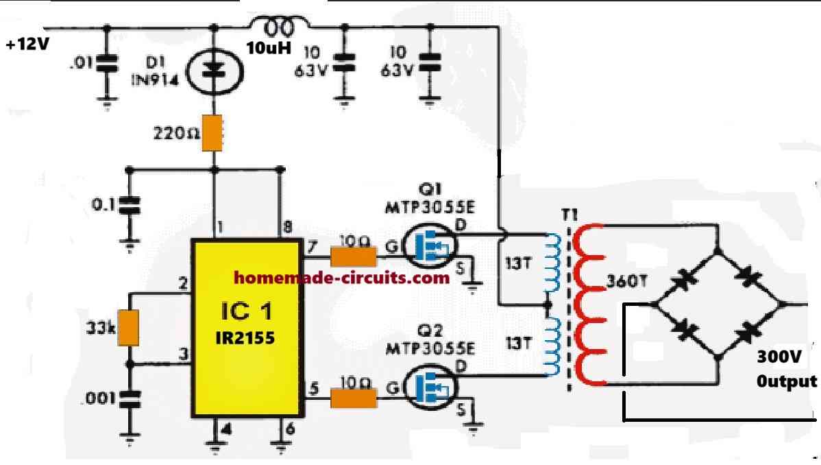
      I think you can try the following design:
      " rel="ugc">comment image
      The output winding of the ferrite transformer can be increased proportionately to increase the output voltage to 600V.
      The transformer can be wound on any standard ferrite E core transformer.

      Reply
      • Hersan Widiatmono says

        June 22, 2024 at 3:27 pm

        Dear Swagatam, if the supply voltage is 48 Volts, do we just need to multiply the number of primary coils by 4, or does it need to be recalculated. The second question is to make the mosfet power dissipation stronger. Can I use the FGH60N60 mosfet or equivalent. so it’s safer and doesn’t get too hot. or igbt STGW39NC60. Coincidentally there is stock. Thank you, your opinion is very helpful and appreciated

        Reply
        • Swagatam says

          June 22, 2024 at 5:52 pm

          Hi Hersan,
          " rel="ugc">comment image
          I think that should work, for 48V you can multiply the 13 turns into 4 for each of the primary winding.
          Also, you can eliminate all that parts which are just above the 220 ohm resistor, and then replace the 220 ohm with a 10k 2 watt resistor, and also make sure to connect a 15V zener diode across the supply pins of the IC and ground.
          Yes, both of those OGBTs can be tried.
          I would advise you to try the circuit with 12V firstas exactly shown in the diagram….if it works only then go for the upgrade.

          Reply
  4. ciro says

    May 10, 2024 at 8:11 pm

    hi. great job! how i put to 60hz? increase hz on outout of 555?

    Reply
    • Swagatam says

      May 11, 2024 at 8:21 am

      Hi, yes you will have to slightly increase the frequency of the IC 555 output, and confirm the results using an oscilloscope.

      Reply
  5. Prashanth Suvarna says

    January 24, 2024 at 12:57 pm

    Hi Swag! Very good job that you are doing esp regarding Inv and pwr supplies. I’m not sure and I may be mistaken but in the above circuit diagram using 555 to drive 2 of 4017,s, here I’ve noticed that santhosh the circuit appears logically ok, I’ve discovered that the pin numbers of the 4017 ic,s which should have been identical are not the same in both the Ic,s. Is this deliberate and ok or is it a printing error? And also BTW Pz include the winding details of the Opt Trx optimised for 12+12v/150A each or more simply 24/150 Thanks.
    Regards,

    Reply
    • Swagatam says

      January 24, 2024 at 2:05 pm

      Thank you Prashanth, Glad you liked the design.
      Yes the pinout configuration of the two 4017 ICs are not identical and that’s as per the requirement of the circuit so that the two ICs can work in cascaded manner.
      You can use a 12-0-12V transform or a 24-0-24V transformer, rated at any desired current with this circuit, just make sure the battery voltage matches the transformer voltage spec.
      The transformer will need to be order made from a professional transformer manufacturer.

      Reply
  6. Ochima Joh says

    August 8, 2023 at 11:25 pm

    Sir, there’s+12V and +48v. I’m confused. Does it mean we need two sources of DC supply to the circuit?

    Reply
    • Swagatam says

      August 9, 2023 at 9:19 am

      Ochima, you can derive the 12V from the 48V source using a transistor regulator circuit or a buck converter.

      Reply
  7. John says

    December 24, 2022 at 1:55 am

    Please sir i don’t have 48v battery to power this circuit can i use 12v instead and please explain for me how to use BJT transistor

    Reply
    • Swagatam says

      December 24, 2022 at 10:49 am

      You can use a 12V battery also, but to get 1500 watts the Ah value of the battery may need to be around 1000 Ah

      Reply
  8. Richard Jombo says

    December 12, 2022 at 8:15 pm

    Dear Swagatam
    2 questions,
    1) inorder to fine-tune the output voltage, can I connect a feedback loop from the output of the transformer to pin 5 of the 555ic ?
    2) can the outputs of the 4017 be connected to ir2110 to get a full bridge drive as I only have a 3kva 220input, 0 -12v output transformer at my disposal

    Reply
    • Swagatam says

      December 13, 2022 at 9:35 am

      Hi Richard,
      Adding a feedback with pin#5 of 555 will not work. Instead you can configure the feedback with the bases of the left side BC547 transistors, so that these transistors are switched off if an over voltage is detected.
      The outputs of the 4017 are specifically designed to work with a center tap transformer so a full bridge configuration may not be possible here.

      Reply
  9. CHUCK VON BECK says

    June 24, 2022 at 7:14 am

    Hi Swagatam,
    How would you approach a low cost PI controller that can control a 1500W 120V input to a resistive heat element. I need temperature feedback and digital readout and temperature setpoint controls.

    Thanks Chuck.

    Reply
    • Swagatam says

      June 24, 2022 at 9:35 am

      Hi Chuck, this can be perhaps designed using simple circuit stages, but the above article is about a sine wave inverter so we cannot discuss it here. We can discuss it under the following post:
      http://www.homemade-circuits.com/how-to-make-25-amp-1500-watts-heater/

      Reply
  10. PAULO AFONSO SILVA says

    June 21, 2022 at 5:15 am

    Hello Swagatam, I’m Paulo from BRAZIL… Congratulations With praise, for the excellent work you do, in favor of science, contributing enormously, with your spiritual greatness, to serve and at the same time humbly, listen to the other sides, suggesting them ideas and reflections to your projects.

    I come here, to request your knowledge, for some doubts I have, regarding the OFF GRID INVERTER…

    I am an Electronics Technician, and in calculations, projects, I have no competence…

    I would like to hear from you the following:

    I can use 11 BATTERIES in series of 12Vdc, 30 Amps each, making a total of 132Vdc and 330 Amps, and convert straight to 120 Vac, 60 Hz, providing an output, a load of 3,000W, in a PURE SINUSIDE INVERTER ( ~ ).

    Another question, is it possible to extract, obtain from the 120 Vac POWER GRID, the 60HZ, instead of going through the square wave OSCILLATORS and then transforming it into SINUS.
    If possible, I would like to see a project of yours like this, posted here.
    Thanks.

    Olá Swagatam, sou Paulo do BRAZIL…
    Parabéns Com louvores, pelo excelente trabalho que faz, em prol da ciência, contribuindo enormemente, com sua grandeza espiritual, a servir e ao mesmo tempo humildemente, ouvir os outros lados, sugerindo-lhes idéias e reflexões aos seus projetos.

    Venho aqui, solicitar seus conhecimentos, para algumas dúvidas que tenho, no que se diz respeito a INVERSOR OFF GRID…

    Sou Técnico de Eletrônica, e em cálculos, projetos, não tenho competência…

    Gostaria de saber de você o seguinte:

    Posso usar 11 BATERIAS em série de 12Vcc, 30 Amperes cada uma, perfazendo um total de 132Vcc e 330 Amperes, e converter direto para 120 Vca, 60 Hz, fornecendo uma saída, uma carga de 3.000W, em um INVERSOR SENOIDAL PURO ( ~ ).

    Outra pergunta, é possível, extrair, obter da REDE de ENERGIA de 120 Vca, os 60HZ, ao invés de passar pelos OSCILADORES de onda quadrada e depois, transformá-la em SENOIDAL.

    Obrigado.

    Reply
    • Swagatam says

      June 21, 2022 at 9:51 am

      Thank you Paulo,
      You can connect the specified 11 batteries in series but the output current will be 30 Ah, it won’t be 330 Ah since the batteries are in series.
      Yes the 60 Hz wil be required for replicating a synchronized version of the grid AC, but the circuit will be complex. I already have one article on this, as shown in the following link:
      Designing a Grid-Tie Inverter Circuit

      Reply
  11. Sankhaja says

    June 4, 2022 at 1:44 am

    Dear sir.
    If use FET z44

    Reply
    • Swagatam says

      June 4, 2022 at 9:17 am

      Hi Sankhaja, IRFZ44 can be used in the above explained design

      Reply
  12. Roy Bandara says

    April 30, 2022 at 8:38 am

    Dear Sir,
    An inverter driven by 24 DC volts (12 volts/7AH X 02 batteries) , producing approximately AC 200 volts.
    Guess 600VA and performing ok.

    In order to increase the sustain period of the device in the absence of mains, I suggest 01 number 24volts high capacity battery Or high capacity 12 volts 02 batteries, providing external charger for the same.(let’s say 40AH)

    Sir, since the the device was originally designed for a specified time for in the absence of I/P AC. Can the device stand for proposed extended period ?
    Regards et have a nice weekend.

    Reply
    • Swagatam says

      April 30, 2022 at 10:12 am

      Dear Roy,

      Dividing 600 with 24 gives 25 amps.. But 25 amps is too high, it cannot be obtained from a 7 Ah battery.

      Yes you can connect more batteries in parallel to increase the backup time, but make sure not to increase the load beyond the rated capacity of the inverter.

      Reply
      • Roy Bandara says

        April 30, 2022 at 11:15 am

        Dear Sir,
        I doubt, if I submitted my question above correctly to understand anyone.

        There are already inbuilt 12volts/7AH 02 batteries in series in the device.(ie inverter driven by 24 volts DC and producing out put 200 volts AC.)

        I want to replace those batteries with a 24 volts 40AH battery or 12 volts,40 AH 02 batteries in series in order to increase the back up time. (Suggest an external battery charger if necessary )

        01. Is it advisable ?
        02. can the device stand for such proposed extended period. ?
        Regards.

        Reply
        • Swagatam says

          April 30, 2022 at 12:13 pm

          Yes it is fine to increase the Ah rating of the battery for extending the back up time….but you cannot increase the output load wattage beyond the specified rating of the inverter otherwise the internal mosfets and transformer may burn.

          Reply
          • Roy Bandara says

            April 30, 2022 at 1:25 pm

            Thank you sir,
            Answer was very clear and you simply put me in the picture.

            Best Regards.

            Reply
            • Swagatam says

              April 30, 2022 at 1:27 pm

              You are welcome Roy!

              Reply
  13. Roy Bandara says

    April 25, 2022 at 6:02 pm

    Thank you sir, learned a lot from the given file.
    I just want to know any publications of yours,(for international community)
    Best Regards.

    Reply
    • Swagatam says

      April 25, 2022 at 8:47 pm

      You are welcome Roy. I only have this website online and I do not have it published in any other form.

      Reply
  14. Roy Bandara says

    April 24, 2022 at 11:03 pm

    Hi Sir,
    In fact, how do we differentiate between an Inverter and a Ups? The functions of both devices look same.
    If you had answered to this question before , Please tell me where it was I can find.

    My next question is sir, if we don’t know the specifications of a given inverter how we can find the VA of the same ? ( I guess, a known load will be connected to the o/p and wait till batteries totally drained with respect to the time. Is that correct?.),also, the current taken by the inverter circuit is also taken into account.
    Regards.

    Reply
    • Swagatam says

      April 25, 2022 at 9:49 am

      Hi Roy,
      The difference is very basic. An inverter will normally not have an automatic changeover from battery mode to grid mode AC output, whereas an UPS, as the name suggest, will have an uninterruptible output since it features a built-in automatic changeover that will changeover from mains AC to battery mode and vice versa depending on the presence or absence or the grid mains AC.

      Yes the only approximate way to find out the VA rating of an unknown inverter is by draining the battery through a known load, which may be moderately rated.

      The current consumption method can be also tried, but in this method it can be difficult to figure out how much maximum load can be tried without burning the mosfets.

      Reply
      • Roy Bandara says

        April 25, 2022 at 12:35 pm

        Thank you Sir,
        Seeking for further clarification. If it is an off line UPS then it is similar to an inverter as you explained above. Am I correct Sir? ( And all I am referring to small scale, not industrial ones.)

        One last question Sir, (awfully sorry if I’m disrupting you)
        Considering two individual devices such as an Inverter and a UPS having almost similar specs such as
        DC volts, OP power, Q factor, average magnitude value of AC o/p,… so on then connected to identical loads.
        Under no AC i/p condition,
        The sustaining period of each equipment approximately same?
        Regards.

        Reply
        • Swagatam says

          April 25, 2022 at 2:08 pm

          You are welcome Roy, yes I was referring to an off line UPS. You can learn more about them in the following article:
          Different Types of UPS systems – Explained
          Basically an UPS is also an inverter, so if its specifications are exactly similar to another inverter, then the performance of the two systems will be also exactly similar.

          Reply
  15. Roy Bandara says

    April 22, 2022 at 4:01 pm

    Hi Sir,
    I have been repairing an inverter almost similar to ur 04 Mosfet one (but here IRF 3205’s and 12volts x02))
    Rectified the fault, replaced said 04 Mosfets, But a complex issue has arisen. Now the op is nearly 380 volts AC. The OP is loaded , no hum, no over heating. Performing ok apart from the excessive over voltage.
    Sir, what factors determine the magnitude of the op?

    Is it PWM (KA3843 being used),
    Defect of a feed back path,
    Or the transformer.
    Best Regards.

    Reply
    • Swagatam says

      April 22, 2022 at 4:31 pm

      Hi Roy,
      Yes the output voltage can be reduced by reducing the PWM. The transformer can be also responsible, if its winding voltage is less than the average DC value of the PWM.

      Reply
      • Roy Bandara says

        April 22, 2022 at 11:55 pm

        Noted with thanks sir.

        Reply
  16. Roy Bandara says

    April 15, 2022 at 9:43 am

    Hi Sir,
    I found an u/s inverter almost similar to your 04 Mosfets,(IRF3205), body diodes charging 24volts.(12×02 batteries).
    Sir, when powered the unit only 150volts ac o/p appeared, beeps at regular intervals (10seconds) and battery alarm LED blinking simultaneously.
    No o/p load connected, Removed AC i/p. The two batteries are fully charged,. As in your circuit relay controlled.
    Seeking your guidance to rectify the fault.
    Regards.

    Reply
    • Swagatam says

      April 15, 2022 at 1:02 pm

      Hi Roy, Without actually seeing the circuit it can be very difficult to judge the fault. The function may be similar to my circuit but physically there may be a lot of difference, so it can be very difficult to troubleshoot without a practical check.

      Reply
      • Roy Bandara says

        April 15, 2022 at 9:41 pm

        Noted with thanks.

        Reply
  17. Roy Bandara says

    April 6, 2022 at 6:06 am

    Dear sir,
    Why SCR s being used for full wave wave rectifications in inverters instead of diodes/bridges?
    Any specified reason?
    Regards.

    Reply
    • Swagatam says

      April 6, 2022 at 9:51 am

      Dear Roy, SCRs also work exactly like rectifier diodes, the only difference being they can be switched ON/OFF with an external signal. So in inverters there might be a need of a rectifier which can be switched ON/OFF for some specific purpose in the circuit, therefore SCRs may be preferred instead of diodes.

      Reply
      • Kai says

        April 15, 2022 at 8:44 am

        Hi Swag,
        Hope you doing well.
        I am from Sydney, and I am trying to design a grid-tie micro-inverter circuit. Will it be possible to get some help from you, please? It will be appreciable if you contact me. TIA.

        Reply
        • Swagatam says

          April 15, 2022 at 10:49 am

          Hi Kai, I wish I could help you, however I am not an expert with micro GTI circuits, so it will difficult for me to help you with this subject.

          Reply
          • Kai says

            April 15, 2022 at 9:41 pm

            All good mate. Thanks for your early response though. Cheers.

            Reply
  18. Roy Bandara says

    April 5, 2022 at 12:23 am

    Dear sir,
    Is it necessary to have a center tap transformer for final Trs or mosfets in the inverter circuits.?
    I found an inverter using IRF 3205 in which primary winding connected to the drains of mosfets.
    No center tap, but 24 volts given to one end. Out put 230 volts taken by the secondary .
    Regards.

    Reply
    • Swagatam says

      April 5, 2022 at 1:25 pm

      Dear Roy, For the above circuit a center tap transformer will be required. If you use a single mosfet then a two wire transformer can be used, but then the output will not produce a full AC cycle rather a half wave cycle only.

      Reply
  19. yusuf says

    April 2, 2022 at 11:20 pm

    can we add “pwm and output voltage correction circuit” to inverter? If so,why and if not so,why?

    Reply
    • Swagatam says

      April 3, 2022 at 10:26 am

      Yes we can but it is not required, since it is constant pwm oscillator which makes sure the output voltage is constant.

      Reply
      • Roy Bandara says

        April 6, 2022 at 6:00 am

        Thank you sir, I have gone through most of your articles, innovations, teachings, tutorials so on.
        In fact, Sir you are an asset to India.
        Best Regards and best luck for all your future endeavors.

        Reply
        • Swagatam says

          April 6, 2022 at 9:45 am

          It’s my pleasure Roy. Thanks for your encouraging words, appreciate it.

          Reply
  20. Novax says

    April 2, 2022 at 2:42 pm

    Hi Dear Swagatam, can the 555 oscillator circuit be replaced with “EGS002 psw inverter module” ?
    if can, please update the circuit diagram.

    Best Regards
    Novax

    Reply
    • Swagatam says

      April 2, 2022 at 4:54 pm

      Hi Novax, the IC 555 circuit here functions like a simple oscillator or pulse generator. It can be replaced with any other simple astable oscillator, but not with a complex circuit like the EGS002

      Reply
  21. Okafor Fidelis says

    March 14, 2022 at 12:08 pm

    Hi Sir, l appreciate your good works. Please l cant see the components from the circuit diagram of 1,500W inverter and it doesn’t zoom . Can you resolve that please, so that the components will be visible.

    Reply
    • Swagatam says

      March 14, 2022 at 6:00 pm

      Hi Okafor, It is quite visible to me, you can refer to the following image: It zooms when pressed cntrl+

      " rel="ugc">comment image

      Reply
  22. Yusuf says

    January 24, 2022 at 11:53 am

    pin 14 and 16 are used for what purpose?

    Reply
    • Swagatam says

      January 24, 2022 at 1:27 pm

      Pin 14 is for the clock input, and pin16 is for the DC supply to the IC.

      Reply
  23. Bams says

    December 27, 2021 at 10:17 am

    sir
    can the 555 oscillator circuit be replaced with a 50Hz xtal oscillator, to get a pure sine wave?

    Reply
    • Swagatam says

      December 27, 2021 at 10:58 am

      No, that’s not feasible.

      Reply
  24. Eniola says

    November 25, 2021 at 2:53 am

    Thanks sir, for cheering us the concept,may God almighty bless you.amen

    Reply
    • Swagatam says

      November 25, 2021 at 4:05 pm

      You are welcome Eniola….

      Reply
  25. Eniola says

    November 25, 2021 at 2:49 am

    Hi sir, the above cascade ic’s inverter circuit diagram, the 555 output is blocked with the diode in the reverse biased, or was it a mistake? secondly, one of your article I read on the ic4017,is that pin 14 has to be sychronize, but not that was as it is in the diagram,or is that also correct? looking forward to your nippy response.

    Reply
    • Swagatam says

      November 25, 2021 at 4:05 pm

      Hi Eniola, the reverse biased diodes are correct, the 4017 responds to the negative pulse from the IC 555. Please provide the link of the article so that I can understand the explanation and provide the clarification.

      Reply
  26. Bernhard Marius Sauerman says

    November 12, 2021 at 2:12 pm

    Good morning Swagatam,
    Thank for the diagram, in your mail you replied that if I want to up from 1500watt or higher i must go higher on the mosfets and the caps I need to connect in what way (diagram would help a lot) with their values.
    The batteries I currently have is 2 x 12VDC 18aH.
    What must the transformer spec be?
    Thank you for your valued input!
    Best regards,
    Marius

    Reply
    • Swagatam says

      November 12, 2021 at 8:26 pm

      Hi Marius,

      2 x 12V 18 Ah can provide a maximum of 200 to 250 watts. For this 24V battery specifications (2 in series) you can try a 18-0-18V/20 amp transformer or something near to this.

      For 1500 watt you will need a lot more than this, along with more number of mosfets

      Reply
  27. Ricardo A. Berdos says

    September 11, 2021 at 9:58 am

    Thank,s for the design of your sine wave inverter.Can i add 4 or 6 mosfet to have bigger wattage…?

    Reply
    • Swagatam says

      September 11, 2021 at 10:32 am

      You are welcome, yes you can do that!!

      Reply
  28. mohsen says

    August 29, 2021 at 4:47 pm

    hi,
    dear Swagatam ,i’ve a switching power supply that it’s switching ic has been exploded.if i send you the photo of circuit ,can you help me to find the IC number?

    best regards
    mohsen sadighian
    00989125417914
    Zanjan -Iran

    Reply
    • Swagatam says

      August 29, 2021 at 5:52 pm

      Hi Mohsen, I am sorry that can be very difficult, because there are many different ICs that are used in SMPS circuits, and identifying the specific one can be very difficult unless we have the complete circuit diagram.

      Reply
  29. Nimel says

    August 26, 2021 at 3:16 am

    Pls sir can u explain (two ic’s has been cascaded) i dont really understand

    Reply
    • Swagatam says

      August 26, 2021 at 7:52 am

      Cascaded means connected in series, one after the other, so that the output sequence follows from one IC to the other, continuously.

      Reply
  30. Hassan is says

    August 18, 2021 at 6:52 pm

    I like it

    Reply
  31. Владимир says

    June 17, 2021 at 10:23 pm

    Полезная хорошая статья, большое спасибо!

    Reply
    • Swagatam says

      June 18, 2021 at 7:35 am

      Glad you liked it!

      Reply
  32. Nkwenti says

    June 7, 2021 at 12:17 am

    Sir please i have an experiment to make but i wanted your advice, can i rectify a transformer, attached a DC battery to it for better DC filtering and connect it to an inverter so to get AC delivered for use?
    Please i wait to read from you.
    Nkwenti.

    Reply
    • Swagatam says

      June 7, 2021 at 10:59 am

      Nkwenti, from where the transformer will derive the input supply from? do you mean using the inverter output to charge the battery in a cyclic manner?

      Reply
  33. BABURAJ says

    December 13, 2020 at 6:28 pm

    Hi, I am looking at High efficient 1500W to 2000W Solar Power for my home with 5 hours of power backup…Request you to publish a PIC based ckt with pure sinewave AC output. Also Primarily Battery should charge from Solar panel and if no proper sunlight then battery should charge from the Grid..

    Initially I thought to purchase it but I had checked with a vendor, he had qoute me 1.20L for 2000W, Thought let me build it myself..

    Reply
    • Swagatam says

      December 14, 2020 at 12:40 pm

      Hi, sorry I do not have a PIC based design with me at this moment with me.

      Reply
      • AHMED REHMAN says

        February 10, 2021 at 6:40 pm

        what is the component name of E-MOSFET in proteus

        Reply
        • Swagatam says

          February 11, 2021 at 9:57 am

          Sorry no ideas….

          Reply
  34. David Hernandez says

    October 21, 2020 at 5:01 pm

    Good Morning,

    Very nice website… I am interested to have a complete circuit design to connect a solar panel 300w into a circuit to produce 120 AC/60 Hz/ 20 Amp. (willing to pay for the design).
    Solar Panel Specs: (to install 2 solar panels in parallel).
    Open Circuit Voltage: 38.80V
    Opitmum Operating Voltage: 32.20V
    Optimum Operating Current: 9.32A

    Reply
    • Swagatam says

      October 21, 2020 at 8:46 pm

      Thank you, and glad you liked it!

      You can probably build the circuit explained in the above article for your specific need, and hook it up straight with your 38 V panel.
      The only criteria being, the transformer and the 100 ohm resistor which will need to be replaced with a 24-0-24V transformer, and a 2k2 10 watt resistor respectively.
      Additionally you can add a couple of more MOSFETs in parallel with the indicated ones, for ensuring a much higher efficiency in terms of power optimization.

      Reply
  35. KV Prakash says

    October 14, 2020 at 2:52 pm

    Hi,

    I am working on developing a power box powered using lithium batteries and requirement is 1 kva power pure sinwave without transformer. Battery we can have multiple packs..Individual cells come at 2.7 v appx and packs can be arranged to have specific voltage and power.
    Can you help with good circuit to weigh less and have simplest but robust technology.

    Reply
    • Swagatam says

      October 15, 2020 at 6:27 pm

      Hi, you can try modifying the above explained concept in the following shown manner:

      comment image" alt="pure sine wave inverter full bridge" />

      This will be a 250 watt model, if it works you can increase the current capacity by prortionately increasing the number of parallel MOSFETs and the battery mAh rating

      Reply
      • Luke says

        March 1, 2021 at 12:13 pm

        What would the efficiency of this inverter be?

        Reply
        • Swagatam says

          March 1, 2021 at 2:31 pm

          around 80% with iron transformer

          Reply
      • Swagatam says

        June 22, 2024 at 5:41 pm

        I want to add an update here, very sorry for the incorrect diagram, the above H-bridge circuit will not work with 310V, it will work only with a 12V DC.

        Reply
  36. suat kaleli says

    September 1, 2020 at 12:05 am

    Hi Mr Swagatam;
    To understand the matter I made an simple circuit with 555 and IRF44 and by using 12 V DC 2 Amper input and I gained 220 V AC and 15W bulb was ON. However I am not able to measure output AC voltage since I measure live voltage at both side of output. Whenever I try to gauge AC output voltage then my multimeter shows error and short contact occurs again on the rotary switch terminals by excluding the fuse error. Thanks in advance

    Reply
    • Swagatam says

      September 1, 2020 at 1:22 pm

      Suat, either your meter is faulty, or may be the frequency is too high. Make sure the frequency is 50 Hz, also test the meter in your 220 V home AC socket for verifying its condition.

      Reply
      • suat kaleli says

        September 1, 2020 at 9:27 pm

        Lots of thanks Swagatam for he reply, however when I remove the short contact residue on my meter no problem on meausuring the home 220 AC voltage but after measuring the my circuit output then I am about to face the same problem. And also I have got 2 pencil types of meter one shows light if there is AC and other also shows the AC value. After receiving your reply, I have decreased frequency in the degree of that I can watch (as if blinking mode) I tested and again see the 110 AC at both side by measuring pen type meter. One side seems clear 110 V and other side seems inactive / pale written on the display / screen of the pen type meter. (it seems 110 AC since my input is 5 V DC there is no problem I am sure if I would increase the input DC voltage the output will be higher)

        Reply
      • suat kaleli says

        September 2, 2020 at 1:04 am

        Hi Dear Swagatam; this is an amendment to my latest report. Please consider the following measurement is correct one.
        My pen meter shows the home AC measurement as:
        live side: 12 36 55 110 220 (AC 220 is active)
        notr side : shows only the value 12
        the meter also shows the inverter outout as:
        at the both side 12 36 55 110 (as I said before the value at one side is pale) The point is being interesting that although there is no output voltage on the meter the bulb 15 watt is ON.

        Reply
        • Swagatam says

          September 2, 2020 at 9:37 am

          Hi Suat, please use a standard digital multi-meter with red/black probes, for verifying the results correctly, any other form of meter is not recommended for electronic circuit testing and troubleshooting.

          Reply
      • Widiatmono Hersan says

        October 14, 2020 at 11:18 am

        Dear Mr.Swagatam

        I want to ask and comment on the inverter with the 48V battery that you designed. I have tried to make it and the results are good, my question is, if we are going to increase the power output capacity to 6 kW, our power mosfets are parallel 5 mosfets each. What transistor drivers need to be replaced with BC141 for example so that the driving power is large enough, another thing is that each gate needs to be installed with a resistor of about 5 ohms so that the signal is evenly distributed to the gate. ask for an opinion and explanation and thank you for your attention

        Best regards,
        Widiatmono

        Reply
        • Swagatam says

          October 14, 2020 at 8:01 pm

          Hello Hersan, I am glad you could make it successfully.

          Nothing needs to be changed in the circuit, no matter what output power is selected, except the transformer, MOSFETs and the Battery.

          Gates will not need any resistor for all the parallel MOSFETs in this circuit….you just need to connect their G,S,D pins together in parallel.

          Reply
  37. Desmond says

    August 16, 2020 at 1:26 pm

    Hi Sir,

    For the timer 555 pin 3 will it get square wave form? because I using Simulation only give me constant voltage.

    Reply
    • Swagatam says

      August 16, 2020 at 5:35 pm

      Hi Desmond, it will be in the square wave form!

      Reply
      • Desmond says

        August 16, 2020 at 6:45 pm

        ok got it my mistake enter wrong value. then for 4017 which out measurement should i take?

        Reply
        • Swagatam says

          August 16, 2020 at 8:45 pm

          the output frequency measurement should be taken at the MOSFET gate, or transformer output

          Reply
          • Desmond says

            August 18, 2020 at 8:30 pm

            ok thank. just one last thing . do u have the BOM list for this circuit? if yes can u list it down?

            Reply
            • Swagatam says

              August 20, 2020 at 9:41 am

              I will try to update it in the article, if possible…

              Reply
  38. MABANA KABUNA says

    August 14, 2020 at 5:50 am

    Dear Swagatam,
    Thank you for your response. May you please clarify me about the voltage and current used to calculate the power of the resistor(10k) in transistor BC547. According to the formula you used in that 1500W inverter circuit: R =(1/4)x(W)x(5%).

    Reply
    • Swagatam says

      August 14, 2020 at 10:23 am

      Dear Mabana, for high impedance (resistance) loads like mOSFeTs the calculation is not critical. For example instead of 10k you can use 22k or 47k or even 100k.

      for other loads you can use the formula which is explained in the following article:

      Transistor Relay Driver Circuit with Formula and Calculations

      Reply
  39. MABANA KABUNA says

    August 12, 2020 at 6:31 am

    Dear Swagatam,
    I am about to implement the 1500W inverter circuit design. May you please guide me to determine the resistors values of the transistor BC547: 10K and 1K.
    Also I would like to know how to determine the number of Mosfet to be used in that circuit.

    Thanking you in advance for your assistance.
    regards,
    Mabana Kabuna

    Reply
    • Swagatam says

      August 12, 2020 at 6:21 pm

      Hello Mabana, if you are referring to the wattage of the resistors, they are all 1/4 watt 5%

      the number of MOSFETs can be 5 on each side.

      Reply
  40. Desmond says

    August 11, 2020 at 6:48 pm

    Hi Sir, One question for the 48 V and 12 V is it connected together or i just choose one ?
    Sorry this is my first time doing this project.

    Reply
    • Swagatam says

      August 12, 2020 at 2:05 pm

      Hi Desmond, they are supposed to be from different sources, however the 12 V can be derived from the 48 V also, by replacing the 100 ohm resistor with a 1 K 5 watt resistor

      Reply
  41. MABANA KABUNA says

    July 2, 2020 at 1:16 pm

    Dear Swagatam,
    Thank you very much for your response.
    May you please provide me a list of Technical specification of the components used in your design “1500 watt PWM Sinewave Inverter Circuit”. I am thinking to update it to 2000W if possible and combine it with Raspberry-Pi.
    Kind regards,

    Augustin Kabuna

    Reply
    • Swagatam says

      July 2, 2020 at 5:33 pm

      Dear Mabana, everything is standard in the diagram. You can copy the parts from the diagram, and procure them.
      For 2kv you may have to add a couple of more MOSFETs in parallel, and upgrade the transformer accordingly.

      Reply
  42. MABANA KABUNA says

    June 29, 2020 at 4:51 pm

    Dear Swagatam,
    Thanks for sharing your ideas in this field of electronic.
    I would like to build solar inverter using Raspberry-Pi. May you please provide me the details specification for your design: 1500 watt PWM Sinewave Inverter Circuit.
    Please if you have some suggestions for that project of mine, you are welcome for discussion.

    Kind regards,
    Augustin Kabuna

    Reply
    • Swagatam says

      June 29, 2020 at 6:50 pm

      Dear Mabana, I am sorry, Raspberry is not within my field of expertise so it can be difficult foe me to suggest you on this subject.

      Reply
  43. Francisco López says

    May 23, 2020 at 8:42 pm

    Swag you are an excellent professional and a true passionate about electronics, I am an electrician but I am still passionate about electronics, I appreciate that you share your knowledge and your projects. I am from Venezuela today the electrical system is very deteriorated and I want to put together simple projects that can contribute to improving quality of life.

    I will build this wonderful project greetings

    Reply
    • Swagatam says

      May 24, 2020 at 7:57 am

      Thank you Francisco, I appreciate your kind feedback, and wish you all the best with this project!

      Reply
  44. Hansley says

    April 21, 2020 at 4:43 am

    Hello what frequency out will I have if I have 4khz input to 4017s

    Reply
    • Swagatam says

      April 21, 2020 at 10:34 am

      Hi, Divide it with 18

      Reply
  45. Patrick says

    March 18, 2020 at 4:01 pm

    Hello sir,
    Thank you so much for the answer you provided to my earlier question.Please i would like to build the 1500kva sine inverter with a transistorised astable multivibrator with two square wave outputs.How can i do away with the 555 timer on your circuit and incorperate my sq wave circuit and still retaining the two 4017 ic.How many and the values of capacitors to be added at the output to improve the wave form and i would like to know why it has no feedback to avoid output voltage drop at addition of loads.
    Thank you in advance,i am looking forward to your reply.

    Reply
    • Swagatam says

      March 18, 2020 at 5:26 pm

      Hello Patrick, you just have to remove the IC 555 stage and replace it with transistor astable. Use one of the collectors of the astable transistor and connect it to the point where pin#3 of the IC 555 is connected.

      You an add 5uF/400V for the output capacitors. Feedback is avoided for simplicity. voltage will not drop by much as long as the load wattage is within the battery capacity.

      Reply
  46. Josh says

    March 17, 2020 at 2:38 pm

    Hi
    Thanks for such informative information really enjoy it. Just want to know if you have a 1500w, 240vac inverter circuit with the charging circuit.
    Regards

    Reply
    • Swagatam says

      March 17, 2020 at 4:20 pm

      Hi thanks, I have many charger circuits explained in this website, you can select an appropriate one and use it in conjunction with this design

      Reply
  47. Bios says

    December 4, 2019 at 9:59 pm

    Hello sir: if i use 2n3055 transistor will it work as mosfet do?

    Reply
    • Swagatam says

      December 5, 2019 at 10:29 am

      You will have to use it Darlington form, but still it won’t produce more than 200 watts.

      Reply
    • Haruna says

      February 5, 2020 at 1:01 pm

      sir please i want to build 1000 watt inverter how can i calculate ,
      1. the size of transformer to use
      2.how to calculate the number of mosfets to use
      3.how can i know that both transformer and mosfets will give me 1000 watt

      Reply
      • Swagatam says

        February 5, 2020 at 4:48 pm

        Haruna, you can read the following article for the required details

        https://www.homemade-circuits.com/how-to-calculate-and-match-inverter/

        Reply
  48. Bios says

    December 2, 2019 at 2:45 pm

    Hellow Sir can i use irf 540n mosfet?

    Reply
    • Swagatam says

      December 2, 2019 at 4:38 pm

      Yes you can, but add a few in parallel for better efficiency

      Reply
  49. Graeme says

    December 1, 2019 at 11:16 pm

    Great design. Is it possible to increase the output power by adding additional output output stages (drivers, FETs and transformers) in parallel? I think they do something like that with the commercially available devices for the grid tied systems. How complicated is this to acheive? Thanks.

    Reply
    • Swagatam says

      December 2, 2019 at 8:36 am

      Thank you, the power can be increased to any limit by modifying the battery, MOSFETs and the transformer, but Grid integration will require accurate synchronization of the frequency and RMS

      Reply
  50. Bios says

    November 29, 2019 at 9:44 pm

    Hellow Sir is fan necessary in this circuit for cooling? if it is how can i connect it?

    Reply
    • Swagatam says

      November 30, 2019 at 11:39 am

      It will depend on the load, if it’s fully loaded then a fan may be needed….you may apply the last circuit from this post

      https://www.homemade-circuits.com/lm35-circuit/

      Reply
  51. Bios says

    November 28, 2019 at 5:00 pm

    Hello sir: what if i will use 1n5406 diode instead?

    Reply
    • Swagatam says

      November 29, 2019 at 11:06 am

      The difference is only in the maximum tolerable voltage levels, please compare the two through their datasheets and you will be able to understand the difference.

      Reply
  52. Patrick says

    November 25, 2019 at 7:27 pm

    Dear Swag
    Thank you so much for the wonderful elect. Engineering package from you to the world for free. I am sure many would not like to do it and keep it to themselves.
    I have been regularly visiting your cite for various elect,circuits but the pwm sinwave inverter has taken my whole attention.I was taught on sq wave inverter by friend in polytecnic school and it worked fine ,but i want to build a pure sine wave circuit.
    Please among your two or three spwm circuit descriptions,which one is the best if i want to build like 1500va.
    I would also like to know why you leave some finishing touches on some circuit to the intended hobysts and builders ,like tank circuit you talked at the output .How can one know he achieved a bether result in absence of an oscilloscope to check output wave?
    I did my I.T in Indian acquired firm in Nigeria.I photocopied an inverter booklet from a friend from an indian.One circuit talked about using a tank circuit where inductor and capacitor reactance are equal and connected to the transformer input to achieve a pure sinwave and not at the output.What do you say on this?
    Thank you,

    Reply
    • Swagatam says

      November 26, 2019 at 12:07 pm

      Thank you Patrick, the above circuit is best sine wave inverter you can have in terms of simplicity and accuracy. If you can compromise with light lower sinewave quality, then you can try the following design which is ee simpler than the above:

      comment image" alt="" />

      As you can see adding a filter at the output side is much easier and can be implemented with some trial and error and with minimum losses. Moreover you can achieve pure sine results even without an inductor, because the secondary winding itself acts like an inductor, therefore this looks a simpler and more effective option.

      Reply
      • Bios says

        December 11, 2019 at 1:48 am

        Sir I have 2n3055 transistors can i place them instead of TIP 35?

        Reply
        • Swagatam says

          December 11, 2019 at 12:04 pm

          you can after adding a TIP122 in Darlington with the TIP35

          Reply
  53. Bios says

    November 25, 2019 at 6:13 pm

    Sir I want 500watt only can i use 12-0-12 transformer and 12v 100ah battery?

    Reply
    • Swagatam says

      November 26, 2019 at 9:37 am

      Bios, use a 300 watt transformer for getting 300 watt power

      Reply
  54. Bios says

    November 24, 2019 at 7:45 pm

    Hello Sir: would this inverter power small appliances like televisions, and phone charger

    Reply
    • Swagatam says

      November 25, 2019 at 8:53 am

      Hi Bios, yes it can be used for powering all types of electronic equipment

      Reply
  55. Gabriel Maffla says

    November 2, 2019 at 2:08 am

    Regards. 400 W at 60 Hz is enough for me and I only have a 12 V / 60 W solar panel as a source. Can I implement it? What should i change? You help me?

    Reply
    • Swagatam says

      November 2, 2019 at 11:55 am

      60 w panel will not produce 400 W

      Reply
  56. Jorge Delgado says

    May 28, 2019 at 6:14 pm

    Cordial Greeting, I congratulate you on your excellent page.
    I have proposed to design the inverter that is very interesting but a question arises, adding another power transistor in parallel I can place it completely in parallel or I must place a resistance, and of what value, to the Gate of the transistor, thank you very much for your attention and collaboration.

    Reply
    • Swagatam says

      May 28, 2019 at 7:23 pm

      Thank you jorge,

      You can place the mosfets directly in parallel, no need of any resistor or transistor

      Reply
  57. Hassen says

    April 30, 2019 at 1:19 am

    ok swag thank you for you respect full replay, i will see you next days if you can.

    Reply
    • Swagatam says

      April 30, 2019 at 8:08 am

      You are welcome Hassen!

      Reply
  58. Hassen says

    April 28, 2019 at 2:03 pm

    Dear swag, Thanks so much for your useful information and guiding for different persons who are interesting to study and work on this course. , if you have please bring me a document which basically explains the design calculation of “designing inverter using SPWM technique”

    Reply
    • Swagatam says

      April 28, 2019 at 9:46 pm

      Thanks Hassen, I have not yet investigated the calculations of SPWM, but I may surely look into it and present a new article on it, possibly soon!

      Reply
  59. Tolu says

    April 17, 2019 at 11:05 am

    Please can I use a battery charger to run an inverter. Pros and cons

    Reply
    • Swagatam says

      April 17, 2019 at 1:32 pm

      If its current is high enough then you can use it for testing the inverting

      Reply
      • Tolu says

        April 17, 2019 at 2:53 pm

        Can’t it be used to run small loads

        Reply
        • Swagatam says

          April 17, 2019 at 4:14 pm

          Please explain the purpose so that i can understand the reason behind using a power supply to run an inverter.

          Reply
          • Tolu says

            April 18, 2019 at 4:31 pm

            I have 24v battery bank and 400w panel connected to 2kva inverter. I also have 48v /20amps battery charger. I want to build 48v/2kva inverter to connect with the charger for better efficiency with my loads, because I can’t buy more batteries for now. Please educate me . thanks sir

            Reply
            • Swagatam says

              April 18, 2019 at 4:40 pm

              So you want to charge the battery bank with the solar panel, and then use the charged battery in parallel with a 48V mains converted DC for operating the inverter?? No problem, You can do that!

              Reply
  60. NISHANT says

    March 20, 2019 at 4:15 pm

    sir,
    I have a luminous sine wave inverter…….
    recently it is
    1.Not giving output with battery(gives output when mains connected).
    2.On connecting battery……all led display lights glow for 2 sec then gets off.
    3.Outer Fuse
    What could be the problem…….which components on the PCB should i check ?

    Reply
    • Swagatam says

      March 20, 2019 at 4:24 pm

      Hi Nishant, connect a load and then connect the battery. Check if the load is also activating for 2 seconds or not.

      If yes in that case the relay changeover circuit could be malfunctioning, the relay may not be holding to keep the battery connected with the inverter.

      If the load does not activate then the problem could be more complicated, in that case you may have to manually bypass the battery line connecting the inverter and do the further checks depending on the results.

      Reply
      • NISHANT says

        March 21, 2019 at 12:49 am

        thankyou sir for the reply

        Reply
  61. Lins Roberto Pereira, says

    March 12, 2019 at 6:32 am

    O QUE TENHO QUE FAZER PARA MUDAR PARA 110V NO SECUNDÁRIO? OBRIGADO.

    Reply
    • Swagatam says

      March 12, 2019 at 8:13 am

      Use um enrolamento secundário de 110V para o transformador, isso é tudo. Nenhuma outra mudança necessária no circuito

      Reply
  62. sinoda says

    December 17, 2018 at 10:39 pm

    sir gud day…I tested the circuit frequency and waveform at the collectors of two bc547 using my DIY soundcard Oscilloscope, the output frequency 52.9 hz and the wave was like this:
    https://www.4shared.com/photo/XSIBuOsKee/1500_watt_PSW_inverter.html
    is that ok sir?I’m a bit confuse becoz ist very distorted square wave…pls help me how to enhance this sir.

    Reply
    • Swagatam says

      December 18, 2018 at 6:45 am

      Good day Sinoda, yes that’s OK, you can adjust the upper and the lower waveform uniformly to make it look perfect…it will be distorted slightly, because there will be always some spike and transients and harmonics, but those can be countered by adding a small value capacitor at the secondary side of the trafo.

      Reply
  63. Nkwenti says

    September 14, 2018 at 6:36 pm

    then can i replace the mosfets with IRF540?

    Reply
    • Swagatam says

      September 14, 2018 at 7:55 pm

      yes you can

      Reply
  64. Nkwenti says

    September 14, 2018 at 6:26 pm

    Sir can you explain a little about the transformer, you said primary 40-40 , where you trying to say secondary? then what about i replace the 1N5408 with 4007?
    then if i use 4 pair of mosfet transistors, will it deliver more power? what is the maximum secondary amperes of the transformer, then sir please do you have a 50AMP battery charge controler schematic for the solar?
    thanks and i will be looking forward to hearing from you.

    Reply
    • Swagatam says

      September 14, 2018 at 7:55 pm

      NKwenti, The input winding is always referred to as the primary, so here since the 40V side is the input it is the primary.

      The requirement for the mosfet is to have a specification higher than the maximum load wattage, you can satisfy this using 2 or 4 mosfets depending on the the selection…the same goes for the transformer secondary:

      https://www.homemade-circuits.com/how-to-calculate-and-match-inverter/

      there are plenty of battery charger circuits in this website, please use the search box and then you can select the one which suits you the best…

      Reply
  65. Kassim Abba Dandago says

    September 10, 2018 at 6:06 pm

    Hi. Please what are the filter components to use at the output of the iron core transformer?

    Reply
    • Swagatam says

      September 10, 2018 at 6:12 pm

      Hi, the secondary transformer winding will itself act like an inductive filter, still you can add a 0.22uF or a 0.47uF/400V capacitor across the coil and check the response….check with a load connected.

      Reply
  66. Nkwenti says

    August 1, 2018 at 8:38 pm

    can the mosfets be replaced with IRF540?

    Reply
    • Swagatam says

      August 2, 2018 at 12:10 pm

      yes, if your requirement is within the mosfet’s rating specs

      Reply
  67. Saeed Mahdavi Asl says

    July 30, 2018 at 3:23 pm

    Dear Swagatam:
    Thanks a lot for your useful info on electronics and guiding us to this course.
    would you please explain more about how to parallel transistors??
    and how to connect them in series ???
    thanx a lot
    Your Sincerely Saeed

    Reply
    • Swagatam says

      July 30, 2018 at 3:27 pm

      Thanks Saeed, I already have one related article posted in this website which explains the right ways to connect transistors in parallel, you can read it here:

      https://www.homemade-circuits.com/transistor-facts/

      Connecting transistors in series is normally not practiced in electronic circuits and it may not be recommended also.

      Reply
  68. Jojo says

    July 21, 2018 at 4:05 pm

    7808ic is a voltage regulator. So how can it work as AND gate?

    Reply
    • Swagatam says

      July 21, 2018 at 4:24 pm

      sorry, it is 7408 and not 7808

      Reply
  69. Jojo says

    July 21, 2018 at 12:50 pm

    Thanks sir.I have Google it but I didn’t understand how to use it.pls give me any one with the pins out that you know according to my description of that diagram.

    Reply
    • Swagatam says

      July 21, 2018 at 1:41 pm

      you can use 7808 IC which has AND gates inside it, just check which pins connect with the those oval shaped designs inside the IC, and replace those pinout with your AND gates shown in your inverter circuit

      Reply
  70. Jojo says

    July 20, 2018 at 10:07 pm

    Sir swag,pls i dont know how to configure this (AND gate) with this microcontroller. Pls give me any circuit relating to AND gate.check the schematic here. 4.bp.blogspot.com/-Llu4f6lzODA/UR-Gya40gGI/AAAAAAAAAbM/nuos2eLOTSs/s1600/pic+config.png

    Reply
    • Swagatam says

      July 21, 2018 at 9:26 am

      Please Google for “AND gate IC” and integrate the selected IC pinouts accordingly

      Reply
  71. King says

    July 13, 2018 at 2:41 am

    Good day Mr. Swag, can the above concept be implemented with 3kva and above? If yes, what specs of transformer and MOSFETs will you recommend.? And how do I go about the filter part. Thank you, awaiting your reply.

    Reply
    • Swagatam says

      July 13, 2018 at 8:14 am

      Hi King, that is possible. Divide 3000 with battery voltage this will roughly give you the transformer primary current.
      For the mosfet make sure its continuous current and voltage ratings are much higher than transformer rating.
      Battery Ah should be 5 to 10 times higher than the calculated value of transformers current rating

      https://www.homemade-circuits.com/how-to-calculate-and-match-inverter/

      Reply
  72. Jojo says

    June 29, 2018 at 6:02 pm

    Thanks so much swag.Its a final year project and my certificate depend on it.I will try it again.

    Reply
    • Swagatam says

      June 29, 2018 at 8:55 pm

      wish you all the best jojo, if you have any further doubts don’t hesitate to ask them.

      Reply
  73. Jojo says

    June 29, 2018 at 4:53 pm

    Swag,most engineer does not have oscilloscope but I think you will have a design that has lc filter,so pls help me with the one that has giving you good result. Thanks

    Reply
    • Swagatam says

      June 29, 2018 at 5:57 pm

      Jojo, while dealing with a sinewave inverter circuit, an oscilloscope is mandatory, otherwise it won’t make sense.

      Anyway, you can select one of the following designs as per your preference, but all these will again require an oscilloscope for confirmation of waveform and will require an LC filter at the output, I do not have the calculations for the LC filter it will need to be done through manual experimentation.

      https://www.homemade-circuits.com/?s=SPWM

      here’s another good choice

      https://www.homemade-circuits.com/pure-sine-wave-inverter-circuit-using/

      Reply
  74. Jojo says

    June 28, 2018 at 5:00 pm

    I tested it with load like refrigerator and air condition but it did not work fine.pls help me with a better version that is pure sine wave

    Reply
    • Swagatam says

      June 29, 2018 at 8:35 am

      sorry that’s not the way to test and fine tune an inverter output, you must do it through an oscilloscope by analyzing the waveform and then tweak it through a LC filter circuit at the output to achieve the required output. If you do not have an oscilloscope then please do not attempt any of the sinewave inverter circuits.

      Reply
  75. Jojo says

    June 28, 2018 at 3:29 pm

    Pls swag,I av tried this circuit but its not pure sinewave.pls I need your best PURE SINEWAVE CIRCUIT for 5kva/36v battery.

    Reply
    • Swagatam says

      June 28, 2018 at 4:07 pm

      JoJo, how did you check the output waveform?…you will need to check it with an oscilloscope and with a load connected with the transformer. For further improving the results you may try connecting a 105/400V capacitor across the secondary winding output.

      By the way it will not give a best sineave, but much closer to a sinewave

      Reply
  76. Jojo says

    June 26, 2018 at 2:33 am

    Pls sir I need a 48v/5kva pure sine wave inverter circuit that has an automatic battery shut down and no load sencing.

    Reply
    • Swagatam says

      June 26, 2018 at 8:57 am

      Jojo, you can try the above explained concept, the battery shut-off circuit can be easily included later on one the inverter is finalized

      Reply
  77. Giel says

    June 6, 2018 at 3:14 pm

    Hi Swag,

    What is the amp rating on your 40-0-40 transformer

    Reply
    • Swagatam says

      June 6, 2018 at 4:39 pm

      Hi Giel, just divide the required output wattage with 40, this will roughly give you the required amp capacity of the transformer

      Reply
  78. Fardin says

    May 18, 2018 at 2:22 am

    Sir

    Witch transformer should i use for 1000w with 12v 200AH battery

    Thank you

    Reply
    • Swagatam says

      May 18, 2018 at 11:35 am

      Fardin, with a 12V battery the transformer will need to be around 1000/12 = 83 amps, 7-0-7V

      Reply
      • Fardin says

        May 18, 2018 at 11:59 am

        Sir

        Do i have to change the mosfets?

        Reply
        • Swagatam says

          May 18, 2018 at 1:03 pm

          Yes, you can try the following specs:

          https://www.homemade-circuits.com/55v-110a-n-channel-mosfet-irf3205/

          Reply
          • Fardin says

            June 11, 2018 at 5:31 am

            Sir

            From ic1 i’m getting around 6.6vac gate voltage
            And ic2 i’m getting around 5.1vac from gate
            Why this is happening?
            And my ic2 is getting warm
            My suppy voltage was 12vdc

            Reply
            • Swagatam says

              June 11, 2018 at 9:05 am

              Fardin, slight voltage difference at the gates may not be critical, but if your IC is getting warm then that could be an issue. I hope you have connected the reverse diodes across the mosfets, if not please do it and check again.
              Also make sure the IC Vcc is not over 12V.

              Reply
  79. ainsworth lynch says

    April 30, 2018 at 5:38 am

    In the working of this circuit you have 40-0-40v transformer to be used with 48v battery supply, shouldn’t that only be used for a square wave inverter?

    with a spwm inverter shouldn’t the transformer be 24-0-24 for a 48v battery supply?

    Reply
    • ainsworth lynch says

      April 30, 2018 at 5:49 am

      so as an example If I was to use a 12v battery supply transformer would be 6-0-6v, is that correct?

      Reply
      • Swagatam says

        April 30, 2018 at 2:23 pm

        you will have to identify the average ON time % of the SPWM, multiply this % with the battery voltage to get the transformer primary value

        Reply
    • Swagatam says

      April 30, 2018 at 2:21 pm

      It will depend on the average value of the SPWM voltage with respect to the battery voltage. The resultant value can be used for determining the transformer secondary voltage value.

      You can the related information below:
      https://www.homemade-circuits.com/inverter-voltage-drop-issue-how-to-solve/

      Reply
  80. LYNCHPOWER ELECTRONICS says

    April 24, 2018 at 1:51 am

    Good Day,
    Have you tested this design or the arduino spwm design?

    Reply
    • Swagatam says

      April 24, 2018 at 6:47 am

      yes those are tested designs

      Reply
  81. olupot says

    April 12, 2018 at 3:01 pm

    hello sir do you have any idea about self running generator thanks

    Reply
    • Swagatam says

      April 12, 2018 at 8:58 pm

      sorry I do not have any idea regarding this concept

      Reply
  82. bashir says

    April 11, 2018 at 11:55 am

    Sir can i run the above inverter circuit with 12v battery by changing 48-0-48 transform er with 12-012 transformer

    Reply
    • Swagatam says

      April 11, 2018 at 12:31 pm

      bashir, it is possible, but the transformer will need to be rated at 9-0-9V

      Reply
      • Swagatam says

        April 11, 2018 at 12:32 pm

        ..and the mosfets could be replaced with IRF540

        Reply
  83. RAIMUNDO CASTRO SANTOS says

    April 11, 2018 at 4:21 am

    Olá sou do Brasil e acompanho as suas publicações continui com esse bom trabalho tem ajudado muita gente eu fiquei interessado no projeto do inversor senoidal se possivel poderia me enviar o projeto completo por gentileza obrigado

    Reply
  84. fred says

    April 4, 2018 at 4:47 pm

    sorry youupdated already the diagram but one more questions sir the mosfets where is the gate drain and source canyou please put it on each channel thanks..nd more power sir

    Reply
    • Swagatam says

      April 4, 2018 at 5:25 pm

      Fred, the pins which are connected with the transformer are the drains, the pins which are connected with the BC547 are the gates, and the ones which are connected to the negative or ground line are the sources of the mosfets.

      Reply
  85. fred says

    April 3, 2018 at 6:31 pm

    sir swatagam do you have the complete diagram and omponetguide and pcb design for this 1500watts inverter can u please send it o my email thank you it much appreciated…

    Reply
    • Swagatam says

      April 3, 2018 at 8:56 pm

      Fred, I have updated the diagram with more details, please copy the parts list from the diagram, everything has been included according to me….if you have any further doubts, please let me know.
      PCB design is at the moment not there with me, if possible I’ll try to update it soon…

      Reply
  86. saviour says

    April 1, 2018 at 12:20 am

    Thanks a lot mr swag,for the reply ,there are some design i have put-up to that effect using DPDT relays and low battery cut-off protection circuit ,i will send an attachment to you when i conclude.well done!

    Reply
    • Swagatam says

      April 1, 2018 at 10:46 am

      You are most welcome saviour! please keep up the good work

      Reply
  87. saviour says

    March 31, 2018 at 6:18 am

    dear swagatam i really thank you for great work in helping people like us who are born engineers but could`nt afford to study in a Tertiary institution, to navigate our way around in electronic circuit design.
    I conceive an idea, pls check if such idea is design-able.
    i called it P.P.S.S that is permanent power supply system,this is it.You create two inverter system that works in flip flop manna to power a connected load,one will be working while the other is charging,when its battery reaches a certain discharge level the system flips and the other takes over duty without any interruption to the connected load.to reduce cost one transformer may be use for the two of them.

    secondly how can we partner in Nigeria to enter into production of affordable power supply system for the poor people who are paying with their blood just to light candle.

    Reply
    • Swagatam says

      March 31, 2018 at 11:34 am

      Dear Savior, I am glad you liked my website.
      However the idea you have conceived may not work, because the power output from any inverter will be always less than the input battery power consumption, so ultimately the power exchanges between the two inverters will keep reducing until the both the batteries are unable to get charged any longer from the inverter outputs.

      I am really sorry, partnering may not be possible due to the work pressure that I have to handle in the present moment, although I appreciate your offer very much and wish we could partner for this noble cause.

      Reply

Need Help? Please Leave a Comment! We value your input—Kindly keep it relevant to the above topic! Cancel reply

Your email address will not be published. Required fields are marked *

Primary Sidebar

Subscribe to New Circuit Ideas

Categories

  • Arduino Projects (87)
  • Audio and Amplifier Projects (132)
  • Automation Projects (17)
  • Automobile Electronics (101)
  • Battery Charger Circuits (83)
  • Datasheets and Components (104)
  • Electronics Theory (143)
  • Free Energy (37)
  • Games and Sports Projects (11)
  • Grid and 3-Phase (19)
  • Health related Projects (25)
  • Home Electrical Circuits (12)
  • Indicator Circuits (14)
  • Inverter Circuits (87)
  • Lamps and Lights (142)
  • Meters and Testers (69)
  • Mini Projects (46)
  • Motor Controller (64)
  • Oscillator Circuits (27)
  • Pets and Pests (15)
  • Power Supply Circuits (108)
  • Remote Control Circuits (50)
  • Security and Alarm (64)
  • Sensors and Detectors (101)
  • Solar Controller Circuits (59)
  • Temperature Controllers (42)
  • Timer and Delay Relay (49)
  • Transmitter Circuits (29)
  • Voltage Control and Protection (37)
  • Water Controller (36)

Calculators

  • Battery Back up Time Calculator
  • Capacitance Reactance Calculator
  • IC 555 Astable Calculator
  • IC 555 Monostable Calculator
  • Inductance Calculator
  • LC Resonance Calculator
  • LM317, LM338, LM396 Calculator
  • Ohm’s Law Calculator
  • Phase Angle Phase Shift Calculator
  • Power Factor (PF) Calculator
  • Reactance Calculator
  • Transistor Astable Calculator
  • Transistor base Resistor Calculator
  • Voltage Divider Calculator
  • Wire Current Calculator
  • Zener Diode Calculator
  • Filter Capacitor Calculator
  • Buck Converter Calculator
  • Boost Converter Calculator
  • Solar Panel, Inverter, Battery Calculator
  • Wire Current Calculator
  • SMPS Transformer Calculator
  • IC SG3525, SG3524 Calculator
  • Inverter LC Filter Calculator

People Also Search

555 Circuits | 741 Circuits | LM324 Circuits | LM338 Circuits | 4017 Circuits | Ultrasonic Projects | SMPS Projects | Christmas Projects | MOSFETs | Radio Circuits | Laser Circuits | PIR Projects |

Recent Comments

  • Swagatam on Real MPPT Solar Charger Circuit Using Arduino, LCD, and Manual/Auto Switch
  • Obaidullah Khan on Real MPPT Solar Charger Circuit Using Arduino, LCD, and Manual/Auto Switch
  • Swagatam on 2 Compact 12V 2 Amp SMPS Circuit for LED Driver
  • Alan Bishop on AC Motor Speed Controller Circuits using Back EMF
  • Swagatam on Real MPPT Solar Charger Circuit Using Arduino, LCD, and Manual/Auto Switch

Company

  • Privacy Policy
  • Cookie Policy
  • About Me
  • Contact
  • Disclaimer
  • Copyright
  • Videos
  • Sitemap

Social Profiles

  • Twitter
  • YouTube
  • Instagram
  • Pinterest
  • My Facebook-Page
  • Quora
  • Stack Exchange
  • Linkedin
  • © 2025 · Swagatam Innovations