This automatic plant watering circuit can be used for automatically sensing soil humidity and triggering a water pump when the ground gets parched below a predetermined level (adjustable).
Circuit Operation
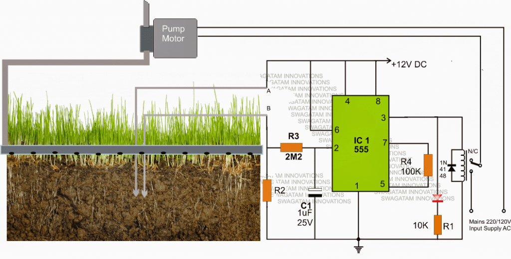
The circuit is rather straightforward and uses a single IC 555 as the main active component.Referring to the automatic plant irrigation circuit shown below we can see the IC 555 is wired in a completely unique and in the quickest possible mode.
Here it's configured as a comparator, and works better than an opamp because the IC 555 has built in opamps which are at par with any single opamp and also the output of a 555 IC is able to sink sufficient current in order to drive a relay without a transistor driver stage.
The above features particularly makes the above design very simple, low cost and yet too effective with its functions.
The pin#2 here becomes the sensing pinout of the IC, and is held at ground level via R2 which must be calculated as per the desired soil humidity triggering threshold.
The points A and B can be seen fixed inside the soil which needs to be monitored for the intended automatic watering from the water pump.
As long as the points A and B senses some level of humidity corresponding to a resistance value which may be lower than R2, the IC 555 output is held low, which in turn keeps the relay deactivated.
However as the soil tends to get dryer, the resistance across the probes starts getting higher and at some moment of time it becomes higher than R2, creating a potential below 1/3rd supply voltage at pin#2 of IC555.
The above situation instantly prompts pin#3 of the IC to become high, triggering the connected relay.
The relay activation switches ON the water pump which now starts pumping water to the particular area of the soil via a distributing water channel.
As this happen, the soil gradually gets wetter and as soon as the predetermined level is reached, the probes immediately sense the lower resistance and revert the IC ouput pin#3 to a low again switching OFF the relay and the water pump consequently.
C1 ensures a slight hysteresis in the operations ensuring that the relay triggering is not sudden or abrupt, rather it switches only after sensing a genuine response from the soil conditions.
Circuit Diagram
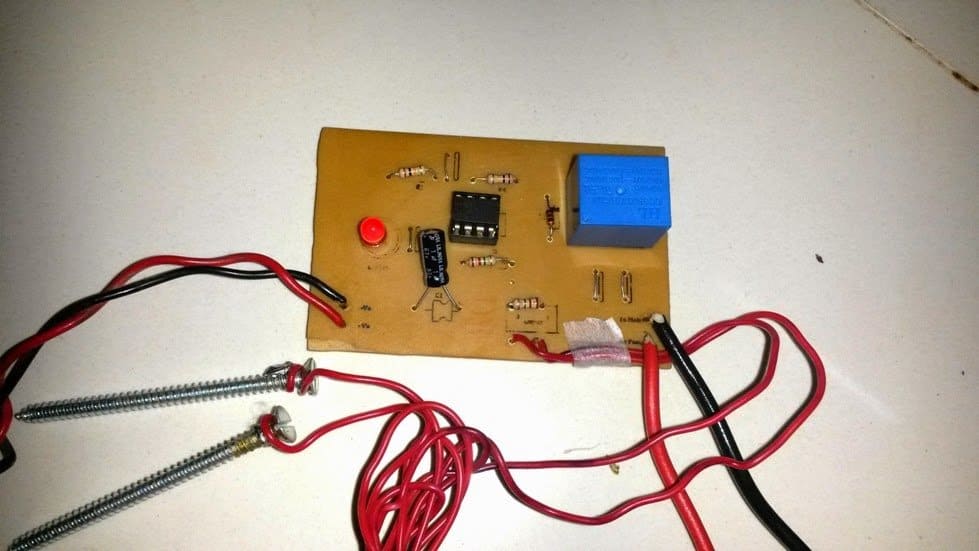
The above explained automatic plant irrigation circuit was successfully built and tested by Mr. Ajay Dussa.
The following images show the prototype unit and the PCB design built by Mr. Ajay.
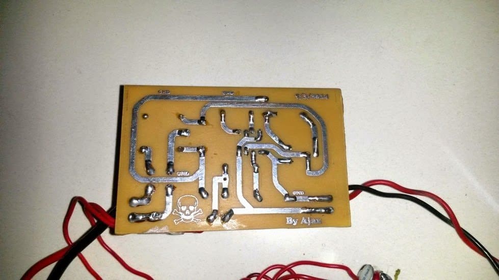
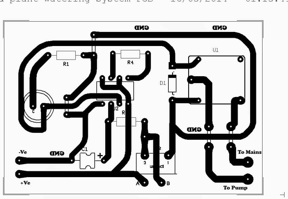
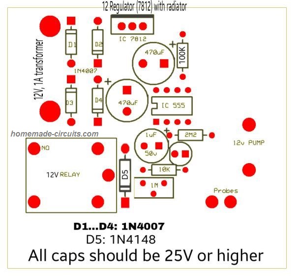
PCB Design
FOR A 741 OP AMP BASED CIRCUIT, YOU CAN REFER TO THIS ARTICLE.
Parts List
All resistors are 1/4 watt 5% CFR
- R1 = 10K
- R3 = 2M2
- R4 = 100K
- R2 = 1M preset or cermet
- C1 = 1uF/25V optional for creating delay effect on the relay
- Relay = 12V, 400 ohm SPDT
- Supply input = 12V/500mA DC
Another version of the PCB design is shown below. It was designed an contributed by: Alireza Ghasemi
Soil Moisture Sensor with Automatic Water Sprayer
The next article explains a 10 stage soil moisture sensor circuit with an integrated automatic water sprayer mechanism for restoring the critical condition of the soil. The idea was requested by Mr. Remy.
Technical Specifications
I come today asking for help making an automatic watering circuit to water my tomatoes for me.
I am requesting the use of a soil moisture sensor (cheap eBay style) to sense the moisture of the soil.
Then the moisture value is compared to a set value from a potentiometer maybe. If level is too low then a relay is turned on for a settable amount of time. After a shower the soil is measured again.
Rise repeat.
The ability to daisy chain many together would be a great help.
For wow factor I was thinking that having a few(3) leds light up as a scale to indicate the current moisture level would work well. Thank you for your time and experience.
I have learned much from you and hope to add this to my knowledge.
Remy
Circuit Diagram
The Design
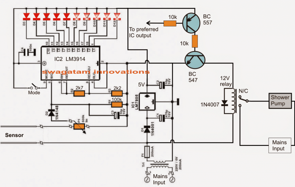
Referring to the given schematic we see a simple yet highly accurate soil moisture sensor circuit with an automatic preset water shower system for restoring the soil moisture level to optimum points.
The design is based on a single voltage sensor/LED driver IC LM3914 or a LM3915. The shown sensor pins which are basically two brass rods are configured as voltage sensors across the critical soil area where it may be inserted.
The voltage across these pins depend upon the level of moisture present across that particular soil area. This sensed voltage proportionate to the soil moisture level is applied across pin5 of the IC for the required comparison with an in-built reference voltage level.
The threshold level at which the shower pump is supposed to be switched ON is set by P1.
Depending upon this setting, the IC internal circuitry senses the soil moisture and produces a shifting sequential low logic across the shown 10 outputs starting from pin1 to pin10.
This sensed output across the relevant IC outputs are indicated by 10 respective LEDs which light up in sequence in response to the rising or depleting soil moisture levels.
Selecting Bar Mode and Dot Mode
The LED illumination sequencing style could be selected to simulate a bar mode or a dot mode by appropriately positioning the pin9 switch of the IC to either ON or OFF.
The stage comprising BC547 and BC557 constitute the relay driver stage for controlling the motor pump switching as per the user preference.
The base of the PNP transistor is appropriately integrated with any of the output pins of the IC depending at what moisture threshold the user wants the motor to be started or stopped.
For example suppose pin15 determines a particular moisture threshold level of the soil and the user feels it to be the unsafe level at which the motor needs to be started in order to restore the soil moisture, then this pinout could be chosen and hooked up with the base of the BC557 transistor for the discussed motor switching.
Once the motor is switched ON the soil is showered until its moisture level is restored to the desired level and this prompts the IC to revert its sequence from pin15 to pin14 and toward pin10, switching OFF the motor and the shower.
The above process keeps repeating making sure that the soil moisture level never goes down below the undesired parched condition.
Simple Transistorized Soil Watering System
Here's another automatic soil watering system that you can build. Its working mode is mainly the nonstop checking of soil moisture, and then responding to a drop beneath a preadjusted degree to set off the plant watering action. This design consists of a straightforward trigger circuit, that switches ON the relay RL for a degree of moisture in the soil and its conductivity which may be beneath the fixed level as adjusted by the 5 k preset.
The conductivity inside the soil or mud is detected through a pair of probes coupled to the terminals as indicated in the diagram. The idea really is easy and very reliable, and will can work by using any supply voltage between 6 and 12 volts or even more, only if the supply voltage is perfectly compatible with the working voltage spec of the relay.
The relay contacts can be appropriately wired with a water pump or a water sprayer device for initiating the required automatic watering of the plant, each time a dry soil is detected and the relay is switched ON.
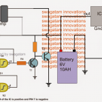
Using Water Control Valve
In the circuit below, whenever the amount of soil moisture exceeds a certain threshold, an electric water valve is shut off. One of the probes is attached to a positive 12-volt supply, while the other probe is hooked to the base of Q1.
The sensitivity is adjusted using resistor R4.
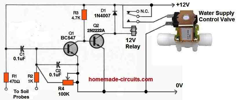
Once the moisture level falls below the predetermined level, Q1 switches off and Q2 switches on, turning ON the relay and supplying power to the water valve.
The water valve begins pouring water into the soil. When this happens the resistance between the two probes starts reducing as the amount of moisture around the probes rises.
Eventually significant current starts passing into the base of Q1 to switch it on and switch off Q2. As a result the relay turns off and the valve loses power. This instantly stops any further flow of water into the soil.
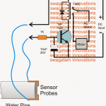
Corrosion Free Automatic Plant Watering Circuit
If the probes are not constructed from high-quality materials, electrolysis may happen and eventually impact how the circuit functions. Cleaning the probes frequently or using a circuit that uses an AC voltage on the probes are two solutions toward this issue.
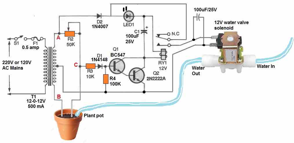
The diagram above displays an AC probe automatic plant watering valve control circuit with corrosion free probes. A 12-0-12V center tapped transformer is wired into an AC bridge circuit.
The soil or mud resistance between the probes along with R2 functions as a couple of variable components of the bridge circuit, with each half secondary winding of the transformer operating as one of the two fixed components.
In order to ascertain the magnitude of a component, such as resistance, inductance, or capacitance, an AC bridge circuit typically balances the bridge with the adjustable component and reads the component's magnitude at balance on the scale.
The output would be an AC signal which is 180 degrees out of phase and equivalent in amplitude on each side of balance.
If a typical AC bridge circuit had been employed for the anti-corrosion soil moisture detector, it would simply show when the ground resistance was close to the preset value of R4. The water valve would shut off once the bridge was balanced, but the water would still percolate into the ground, reducing the resistance between the probes.
As a result, the bridge would become unbalanced, reopening the water valve and flooding the plant soil. Not good at all.
The aforementioned circuit solves the issue by evaluating the bridge's output phase to the secondary of T1's "A" side. The relay would be activated and water would start flowing if the probes were first placed in dry soil with resistance values significantly greater than R4's predetermined resistance value.
It is because:
The voltage is provided to the relay via a 1N4007 diode and the LED whenever the "A" secondary winding of T1 changes from negative to positive.
Due to the resistance value of R4 being significantly smaller than the soil resistance, current is supplied via R3 and D1 to the base of Q1, switching it on.
However, at the same time the output at "C" is also starts becoming positive. Due to this Q2 turns on, switching ON the relay and turning on the water valve.
The bridge becomes balanced and the output voltage at "C" is zero as soon as the resistance across the probes reaches the predetermined value specified by R4. Transistors Q1 and Q2 now switch off, turning off the relay and blocking the water flow through the water control valve.
The bridge turns unstable in the opposite direction as the water seeps into the soil, however the relay is never switched ON.
It is because: Current is able to flow into the base of Q1 whenever the "B" secondary winding of T1 is positive, however no collector current is able to flow since the "A" secondary winding's voltage is 180 degrees out of phase and negative. D2 prevents that negative voltage from getting to the relay and transistor circuits.
The water valve won't turn on until the resistance measured across the probes is less than R4's value. To prevent the relay from stuttering, capacitor C1 is used to smooth out the oscillating DC power supply. Whenever the water valve is switched on, the LED flashes.


Questions & Answers
I can’t say “your awesome
“ enough for your time. I made this circuit, and it works! I’m so happy. I’m trying to set up automation for mushroom grow (fruiting chamber) I thought I may be able to control humidity with this. I tried using a water sensor break out (similar to the edge design you provided,but has three wires instead of two I believe I may have wired it incorrectly, but my problem is when I’m fine-tuning that 1mO megaohm cerment for R2, I can get control to put right on edge of on/off but it starts bouncing on and off. I have the pull down resistor installed in the diagram.
For the probe I m using two wires with ends stripped (28awg pvc coated pure copper wire strands, like bare wire size of 36 awg and about 8 of them. I put the ends into a square piece of Mr clean magic eraser to catch the mist and react with it.
Not sure if that’s right or if it will work. But even with galvanized nails it bounces.
I am glad you could build and test the first 555 based circuit successfully.
Regarding the rapid switching at the cut off thresholds, this could be happening due to a lack of hysteresis.
Although this hysteresis can be tweaked by adjusting the 100k resistor value, a better alternative could be to increase the value of the 1uF capacitor to maybe 47uF or 100uF and check the response…this will certainly control the bouncing range to a much slower levels. Please let me know how it works out…
what is 1n4148 used for
To safeguard the IC 555 from the relay coil’s back EMF current
As I see it, you also power the valve or pump with halfwave-DC but if you already have a transformer with tapped middle, you can easily get fullwave DC. In the pre-silicon-age this was the standard way to rectify AC because vacuum tubes were too expensive for bridge rectifiers. This also balances the load on the transformer.
Thanks for your kind analysis, however because the probes are also wired directly across the transformer secondary AC wires, to mitigate the corrosion effects, adding a bridge rectifier could be problematic here, that is why we have used a single diode rectifier for the “Corrosion Free Automatic Plant Watering Circuit”….
I did not propose a bridge rectifier, but a two way rectifier, because you don’t need it if you have a middle connection in the secondary wiring. The output is only connected to the switched side of the relay and doesn’t affect the measuring side.
See my email with a screenshot.
Sorry for the misunderstanding, yes that’s definitely feasible, it’s just about adding another rectifier diode between the lowermost tap and the existing diode D2 cathode. Thanks for your useful feedback…
It seems to be not. I spent several days searching for the fault, but it seems to disturb the balance. I’ve built the circuit so that I could contact and disconnect the additional diode during operation and when the probes are in water and the LED is off, it immediately lights up and when I contact the second rectifier. May there be a way to re-establish the balance with the additional diode?
Maybe that’s exactly the reason why a second rectifier diode was not included in the design…
At the cathode you get negative potential, but the capacitor is connected to the LED with its positive pol and I measured about -6V.
No, the D2 cathode gives positive voltage, please measure D2 cathode potential with respect to the center tap of the transformer…which is the negative line or the 0V line, so the capacitor C1 polarity is correct.
Can you share the design for this circuit.
Which design? I did not understand your question
I meant how did you get the values for all the components in the circuit.
Here we have used one of the internal opamps of the IC 555 like a comparator. R4 adds a hysteresis to the circuit and was identified through trial and error. R3 and C1 work like timing RC delay network which was also selected with some trial an error and basic experience.
The motor keeps on running even when the sensor is dipped in water.
Which resistor did you select for R2? Touch A/B points manually, check whether the relay is switching or not.
R2 = 1M , manually connecting A and B does not switch the relay, the motor keeps on running.
When you connect A and B, pin#3 of the IC should become low (0V) and the relay should deactivate to N/C points, when A and B are open or have high resistance, pin#3 should become high and the relay should activate to N/O contacts. If this is not happening then something is not correct in your circuit or the IC may be faulty.
Alternatively you can put the 1M across A and B points, and replace R2 with probe contacts and check the response.
Hi,
I just want to ask some questions.
If I need a watering timer which I could set a time(like after 1 hour), and it could continuously working until I set a new time, then what would the circuit like?
Hi, you can a one shot timer using IC 555. When you press the push button the timer switches ON, after the time has elapsed, the timer stops and switches OFF the relay.
You can find a few examples of a 555 one shot timer in the following article:
10 Best Timer Circuits using IC 555
Thanks!!!
Have you any idea for dissolve ozone meter?
Have you any idea for oxygen and humidity meter for air supply?
Please help.
Sorry, I do not have any idea regarding these concepts at this moment.
hi
i made this DIYs
thanks a lot for the idea
however,in order for the circuit to work properly i had to remove the 1uf cap otherwise the reply went on and of so quickly…like a flash…and i cant seem to regulate it accurately…its turns the relay on either when the probes are in a very low soil moisture or it goes off when out of the soil…u see? i cannot seem to regulate it to work with my desired amount of moisture…how can i regulate it more accurately? im using a 1M pot as a regulator resistant…sorry for bad english
Thanks Soheil, try adding a fixed 1 M resistor in series with your 1 M pot and check whether it improves the sensitivity or not…let me know how it works.
thanks it worked… I made a pcb myself.its smaller than yours i guess but the good thing is it also contains a built-in 12v power supply and there are 2 holes on the board which directly supply the 12v pump
tell me if u r interested
would you mind sharing the pcb layout?
sure
in a minute
sir, can i use a 741 op amp in place of 555? if yes what changes should i make?
Yes you can, an op amp circuit will work better than a 555 circuit
I landed here searchin for a circuit non-arduino neither Pi related. Thanks a lot! nowadays It seems everybody is using a microcontroller for turning on a light…….
Thanks, I agree with you, microcontroller should be used only for relatively complex applications, except in tutorial based articles.
Can I put a potentiometer in series to cable “b” to obtain a finer regulation?
potentiometer should be used in place of R2, not with the probe cable….
ok then I’m going to put a 1K potentiometer in series with the 1M preset, to regulate more finely
will do!
Hi, I would like to know what the zener diode is for, I used a 1n4007 and it was the same.
Hi , where is the zener? there’s a rectifier diode across the relay, and a LED at the output
Sir, could you explain the reason for connecting pin 5 and pin 7 together through the 100k resistor? Also please explain the mode in which the timer is operating in this circuit
Sneha, it is included in order to generate some level of hysteresis, and make sure the output does not oscillate rapidly at the cut off thresholds. It is operating in a comparator mode
what are all the components used in circuits sir ???
I have updated it in the article, please check…
If I want to control pump operation time, What is need for this circuit?
If you can, please send me that circuit. ryuma05@naver.com
you will have to insert a monostable multivibrator between the relay and pin3 of the IC, this monostable can be used as a timer for the relay and the motor
Sir, Why don't you comparator like OP-amp instead of NE555?
because IC 555 is more popular and easily available than any opamp