A float switch is a device which detects a fluid level (such as water) and activates a set of contacts which may be further integrated to a control circuit for restricting the fluid flow behavior.
Why a Float Switch
The advantage of a float switch is that it works without a direct contact with the water making the procedure free from all sorts corrosion or mechanical degradation problems.
I have discussed a host of different water level controller circuits in this blog, however all have incorporated a direct contact with water for sensing the levels and for activating the connected control circuits.
It means all the previous circuits could be vulnerable to a long term degradation due to corrosion or oxidation effects.
The present design helps to tackle this issue by describing a non-contact water sensing technique through a float switch mechanism.
The Concept
The idea is actually very simple, here we have a plastic pipe which has a sealed reed switch positioned somewhere within its length where the intended sensing may be required and a plastic ring carrying a permanent magnet secured around the plastic pipe such that the ring slides across the entire length of the pipe freely.
The sliding action of the ring around the pipe should easily take place with the water pressure, meaning the pipe ring must be light enough and should rise or fall in response to the water level conditions, in other words it should float in water, clinging to the pipe since it's secured around the pipe (the pipe running through the center of the ring).
Construction Details
The materials that would be required for making the proposed float switch circuit are as given under:
- 1 inch diameter PVC pipe, length depending upon the water tank depth or as per the user parameter.
- A suitable plastic ring (1 inch thick) having a central hole diameter slightly more than the outer diameter of the pipe.
- A reed switch, quantity will depend on the type of water level sensing application.
- 1 mm dia enamelled copper wire, 5 meters approximately or more depending on the tank depth.
- Epoxy seal, for sealing and securing the outer wire terminals from the pipe and to make the pipe water tight.
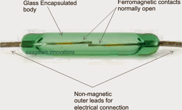
The image below shows a typical reed switch unit. As can be seen it's a tiny (not more than an inch long) glass encapsulated device which encloses a pair of ferromagnetic ( such as iron) open contacts, while the outer terminals being made up of a non-magnetic metal such as copper or brass.
The inner contacts being responsive to a magnetic field, instantly reacts to a magnetic field or lines of magnetic flux when bought at a relatively close proximity resulting in closing of its internal contacts which causes a short or a connectivity across the outer leads.
We use the above explained reed switch in the pipe for detecting the water level conditions via the magnetic ring float either for activating its contacts or vice versa.
Procedure for making a home made float switch device
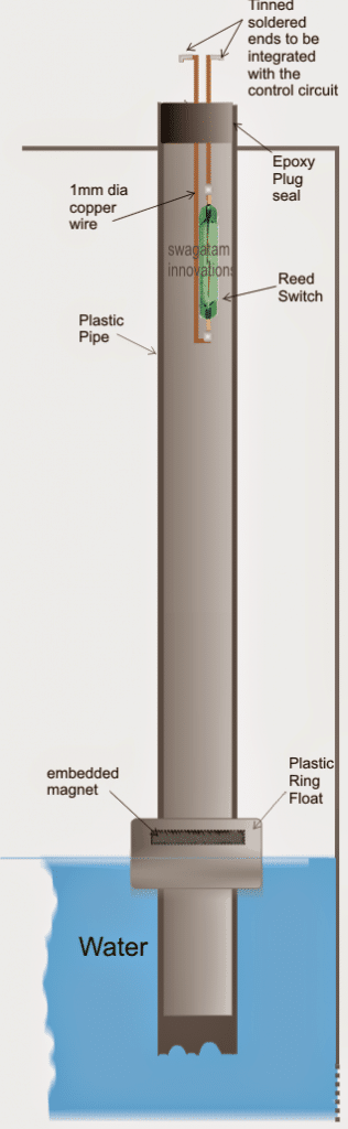
As shown in the figure below, the length of the super enameled copper wire is appropriately measured and soldered with the reed switch ends as indicated in the diagram below.
The wire ends are sealed with epoxy sealant at the mouth of the pipe so that the pipe becomes watertight and also the wire ends get tightly secured. The free ends must be cleaned, tinned with solder and used for further integration with the control circuit.
In the figure below, the assembly suits a tank overflow controller system since the reed switch is positioned at the top of the pipe, near the brim of the tank, similarly more number of such reed assemblies could be used across the different lengths of the pipe for getting the reading and control over the relevant levels of water.
The Design Set up
Making the plastic float could be a little complex, as it will require a thick plastic piece to be fabricated such that it consists a hole which is just enough to the pass the plastic pipe smoothly and freely through it.
The upper/inner rim of this plastic float must allow a magnet insertion, this could be done either by drilling a vertical hole through it and snug fit a rod shaped magnet, or make a U shape slot over the upper surface of the float and embed an identically dimensioned U shaped magnet over it.


Questions & Answers
08 Jun 2023.
Dear Swagatam,
Glad to see this posting of yours using Float Switch for water level sensing. I am sharing my experience with theses as a word of CAUTION to your readers and yourself.
Several dealers in Delhi and one in Bengaluru were my suppliers of these float sensors which can be easily snap fitted on to commonly used 3/4″ plastic water pipes. In the past I have used reed switches of reputed German make in other projects, which always served me for long period without any failure.
One supply from Delhi came with one defective piece as delivered. Still I fitted a few to my water tanks in my house. Within a short time they started failing due to low quality reed switches used.
Generally, good quality reed switches should work for many hundred thousand operations as long as they are used within specs.
But the quality used here is very poor and it is better to avoid these till good ones are available.
Best wishes.
Dr K.V.Venkataramu
Bengaluru
.
Thank you so much Dr K V Venkataramu, for the detailed information about reed switches.
You are right, if the reed switch quality is bad then that is going to affect the working quality of the float switch.
I appreciate your valuable feedback.
Hi Swagatam,
Super interesting 🙂
Floating magnet, reeds & led diodes..
– I am about to make a specific water level sensor – using reeds & led diodes to show the level – in “36 levels” – I have made a graphic representation of it, could I get you to help me out wit the diagram?
(Thou its in “36 levels” its a super minimal approach)
I’ll gladly send you the graphic overwiew
🙂
Henrik
Hi Henrik,
Are you trying to build a 36 LED water level sensor using reed switch, I can help you with that.
Hi Swagatam,
Yes exactly 🙂
– and only one led diode is (/should be) on at a time – the one that correspond to it’s “counterpart reed” (so should not have a huge energy drain)…
How do we do
1. can I email you my graphic showing the idea of what I want to achieve?
2. can you give an quote/ price up front – or perhaps when you see my graphic
3. if so where should I send the graphic – just as a replay to the “***@homemade-circuits.com” i received your “Swagatam has replied to your comment …” Or how do you prefer?
Super thanks for your fast reply.
🙂
Henrik
Hi Henrik,
Graphics is actually not required because your circuit set up is very easy to configure.
You just have to use equally spaced 36 reed switches in a single column. The reed switches will be wired with 36 LEDs, so when the float magnet climbs across the reed switch column it will activate the reed switches in sequence causing the relevant LEDs to light up.
You are most welcome!
Can u please explain how can u switch off a motor using a normally open reed switch? Also I want to add an LED to the circuit. Can u give me any idea how can I implement an LED an an indicator in this circuit.
You can wire the reed switch ends to a relay driver circuit in the following manner, and get the required results:
Hi
I used probe type sensors in OH tank which are available on-line for auto power off of the pump once tank full. It worked well for few months. But due to high scale nature of water, the probes are coated with scales and malfunctioned. Then I replaced with float switch( swing type) and working well, though scales are formed on the outside.
My openions is, any direct contact probes/sensors with high scale nature water will definetly fail, however the circuit is well designed. In your blog suggested to magnetic Reed type in which a ring type float need to slide on pipe. Again the same problem as scales on pipe and will cease/stuck the ring and malfunction.
Conclusion is, for scale nature water, all will fail except swing type float sensing and other electronics.
Raj Kumar.
Hi, it can be eliminated by using AC through the probes
https://www.homemade-circuits.com/anti-corrosion-probes-for-water-level/
Just another idea, we used optical slot sensors with a drinking straw with a little Styrofoam on the bottom. When the water (liquid) got up to the Styrofoam level it floats the foam and straw up into the optical sensor slot and we have zero contact level sensing. We used a little black electrical tape so the sensor can see the straw, and the straw and sensor are captive inside a pvc pipe to maintain position.
thanks, that seems to be a good alternative idea, however optical sensor could be costlier compared to a reed switch/magnet arrangement.
Sir I recently came across ur post about submersible water pump controller.. I would like to know whether float switch will be better for that design or metal contact will be better.. As Ihave a 1 hp submersible pump deep around 150 feet underground.. I want to make it fully autmated .. Kindly help with the design and component required for the process.. Thank you
Hi Automated engineer,
a float switch would be a better and a permanent option.
please provide all the details that you would like to implement for your pump….put them in a sequential form so that it becomes easier for me to understand the entire required functioning.
Hi sir, I want to design an automatic submersible water pump controller.float switch will be better or fully automated water sensor is good.. I have 1 HP submersible water pump around 150 feet deep underground. Kindly help with the schematic design and component required with specification.. Thank you